JEEP GRAND CHEROKEE 2017 WK2 / 4.G Manual PDF
Manufacturer: JEEP, Model Year: 2017, Model line: GRAND CHEROKEE, Model: JEEP GRAND CHEROKEE 2017 WK2 / 4.GPages: 372
Page 71 of 372
GETTING TO KNOW YOUR INSTRUMENT PANEL
INSTRUMENT CLUSTER.......70
Instrument Cluster Descriptions ......73
INSTRUMENT CLUSTER
DISPLAY...................74
Instrument Cluster Display Location and
Controls....................74
Oil Change Reset ...............75
Instrument Cluster Display Selectable
Items ......................75
SRT Performance Features .........76Diesel Particulate Filter (DPF)
Messages
...................76
Diesel Exhaust Fluid (DEF) Warning
Messages ....................78
Diesel Exhaust Fluid (DEF) Fault Warning
Messages ....................78
TRIPCOMPUTER.............80
WARNING/INDICATOR LIGHTS AND
MESSAGES.................80
Red Telltale Lights ..............80 Yellow Telltale Lights
.............83
Blue Telltale Lights ..............87
Green Telltale Lights .............87
White Telltale Lights .............88
ONBOARD DIAGNOSTIC SYSTEM —
OBDII ....................89
Onboard Diagnostic System (OBD II)
Cybersecurity.................89
GETTING TO KNOW YOUR INSTRUMENT PANEL
69
Page 72 of 372
INSTRUMENT CLUSTER
Base Instrument ClusterGETTING TO KNOW YOUR INSTRUMENT PANEL
70
Page 73 of 372
SRT Instrument Cluster
71
Page 74 of 372
Diesel Instrument Cluster
GETTING TO KNOW YOUR INSTRUMENT PANEL
72
Page 75 of 372
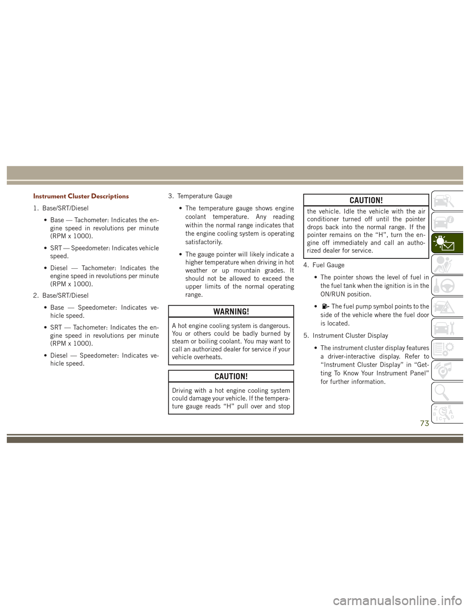
Instrument Cluster Descriptions
1. Base/SRT/Diesel• Base — Tachometer: Indicates the en-gine speed in revolutions per minute
(RPM x 1000).
• SRT — Speedometer: Indicates vehicle speed.
• Diesel — Tachometer: Indicates the engine speed in revolutions per minute
(RPM x 1000).
2. Base/SRT/Diesel
• Base — Speedometer: Indicates ve-hicle speed.
• SRT — Tachometer: Indicates the en- gine speed in revolutions per minute
(RPM x 1000).
• Diesel — Speedometer: Indicates ve- hicle speed. 3. Temperature Gauge
• The temperature gauge shows enginecoolant temperature. Any reading
within the normal range indicates that
the engine cooling system is operating
satisfactorily.
• The gauge pointer will likely indicate a higher temperature when driving in hot
weather or up mountain grades. It
should not be allowed to exceed the
upper limits of the normal operating
range.
WARNING!
A hot engine cooling system is dangerous.
You or others could be badly burned by
steam or boiling coolant. You may want to
call an authorized dealer for service if your
vehicle overheats.
CAUTION!
Driving with a hot engine cooling system
could damage your vehicle. If the tempera-
ture gauge reads “H” pull over and stop
CAUTION!
the vehicle. Idle the vehicle with the air
conditioner turned off until the pointer
drops back into the normal range. If the
pointer remains on the “H”, turn the en-
gine off immediately and call an autho-
rized dealer for service.
4. Fuel Gauge • The pointer shows the level of fuel inthe fuel tank when the ignition is in the
ON/RUN position.
•
The fuel pump symbol points to the
side of the vehicle where the fuel door
is located.
5. Instrument Cluster Display • The instrument cluster display featuresa driver-interactive display. Refer to
“Instrument Cluster Display” in “Get-
ting To Know Your Instrument Panel”
for further information.
73
Page 76 of 372
INSTRUMENT CLUSTER
DISPLAY
Your vehicle may be equipped with an instru-
ment cluster display, which offers useful in-
formation to the driver. With the ignition in
the STOP/OFF position (and the key removed,
for vehicles with mechanical key), opening/
closing of a door will activate the display for
viewing, and display the total miles or kilo-
meters in the odometer. Your instrument
cluster display is designed to display impor-
tant information about your vehicle’s systems
and features. Using a driver interactive dis-
play located on the instrument panel, your
instrument cluster display can show you how
systems are working and give you warnings
when they aren’t. The steering wheel
mounted controls allow you to scroll through
and enter the main menus and submenus.
You can access the specific information you
want and make selections and adjustments.
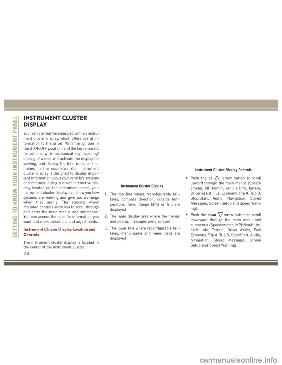
Instrument Cluster Display Location and
Controls
The instrument cluster display is located in
the center of the instrument cluster.1. The top line where reconfigurable tell-
tales, compass direction, outside tem-
perature, Time, Range MPG or Trip are
displayed
2. The main display area where the menus and pop up messages are displayed
3. The lower line where reconfigurable tell- tales, menu name and menu page are
displayed • Push the
up
arrow button to scroll
upward through the main menus (Speed-
ometer, MPH/km/h, Vehicle Info, Terrain,
Driver Assist, Fuel Economy, Trip A, Trip B,
Stop/Start, Audio, Navigation, Stored
Messages, Screen Setup and Speed Warn-
ing).
• Push the down
arrow button to scroll
downward through the main menu and
submenus (Speedometer, MPH/km/h, Ve-
hicle Info, Terrain, Driver Assist, Fuel
Economy, Trip A, Trip B, Stop/Start, Audio,
Navigation, Stored Messages, Screen
Setup and Speed Warning).
Instrument Cluster Display
Instrument Cluster Display Controls
GETTING TO KNOW YOUR INSTRUMENT PANEL
74
Page 77 of 372
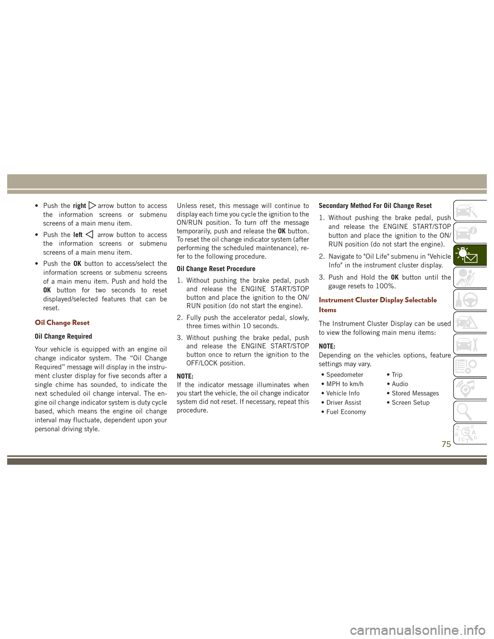
• Push therightarrow button to access
the information screens or submenu
screens of a main menu item.
• Push the left
arrow button to access
the information screens or submenu
screens of a main menu item.
• Push the OKbutton to access/select the
information screens or submenu screens
of a main menu item. Push and hold the
OK button for two seconds to reset
displayed/selected features that can be
reset.
Oil Change Reset
Oil Change Required
Your vehicle is equipped with an engine oil
change indicator system. The “Oil Change
Required” message will display in the instru-
ment cluster display for five seconds after a
single chime has sounded, to indicate the
next scheduled oil change interval. The en-
gine oil change indicator system is duty cycle
based, which means the engine oil change
interval may fluctuate, dependent upon your
personal driving style. Unless reset, this message will continue to
display each time you cycle the ignition to the
ON/RUN position. To turn off the message
temporarily, push and release the
OKbutton.
To reset the oil change indicator system (after
performing the scheduled maintenance), re-
fer to the following procedure.
Oil Change Reset Procedure
1. Without pushing the brake pedal, push and release the ENGINE START/STOP
button and place the ignition to the ON/
RUN position (do not start the engine).
2. Fully push the accelerator pedal, slowly, three times within 10 seconds.
3. Without pushing the brake pedal, push and release the ENGINE START/STOP
button once to return the ignition to the
OFF/LOCK position.
NOTE:
If the indicator message illuminates when
you start the vehicle, the oil change indicator
system did not reset. If necessary, repeat this
procedure. Secondary Method For Oil Change Reset
1. Without pushing the brake pedal, push
and release the ENGINE START/STOP
button and place the ignition to the ON/
RUN position (do not start the engine).
2. Navigate to "Oil Life" submenu in "Vehicle Info" in the instrument cluster display.
3. Push and Hold the OKbutton until the
gauge resets to 100%.
Instrument Cluster Display Selectable
Items
The Instrument Cluster Display can be used
to view the following main menu items:
NOTE:
Depending on the vehicles options, feature
settings may vary.
• Speedometer • Trip
• MPH to km/h • Audio
• Vehicle Info • Stored Messages
• Driver Assist • Screen Setup
• Fuel Economy
75
Page 78 of 372
NOTE:
Refer to your Owner's Manual on
www.jeep.com/owners/manuals for further
information.
SRT Performance Features
Instrument Cluster Display Performance
Features
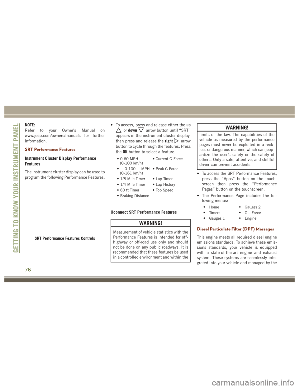
The instrument cluster display can be used to
program the following Performance Features.• To access, press and release either the
up
ordownarrow button until “SRT”
appears in the instrument cluster display,
then press and release the right
arrow
button to cycle through the features. Press
the OKbutton to select a feature.
•0-60MPH
(0-100 km/h) • Current G-Force
• 0-100 MPH (0-161 km/h) • Peak G-Force
• 1/8 Mile Timer • Lap Timer
• 1/4 Mile Timer • Lap History
• 60 ft Timer • Top Speed
• Braking Distance
Uconnect SRT Performance Features
WARNING!
Measurement of vehicle statistics with the
Performance Features is intended for off-
highway or off-road use only and should
not be done on any public roadways. It is
recommended that these features be used
in a controlled environment and within the
WARNING!
limits of the law. The capabilities of the
vehicle as measured by the performance
pages must never be exploited in a reck-
less or dangerous manner, which can jeop-
ardize the user’s safety or the safety of
others. Only a safe, attentive, and skillful
driver can prevent accidents.
• To access the SRT Performance Features, press the “Apps” button on the touch-
screen then press the “Performance
Pages” button on the touchscreen.
• The Performance Page includes the fol- lowing menus:
• Home •
Gauges 2
• Timers •
G – Force
• Gauges 1 •
Engine
Diesel Particulate Filter (DPF) Messages
This engine meets all required diesel engine
emissions standards. To achieve these emis-
sions standards, your vehicle is equipped
with a state-of-the-art engine and exhaust
system. These systems are seamlessly inte-
grated into your vehicle and managed by theSRT Performance Features Controls
GETTING TO KNOW YOUR INSTRUMENT PANEL
76
Page 79 of 372
Powertrain Control Module (PCM). The PCM
manages engine combustion to allow the ex-
haust system’s catalyst to trap and burn Par-
ticulate Matter (PM) pollutants, with no input
or interaction on your part.
WARNING!
A hot exhaust system can start a fire if you
park over materials that can burn. Such
materials might be grass or leaves coming
into contact with your exhaust system. Do
not park or operate your vehicle in areas
where your exhaust system can contact
anything that can burn.
Your vehicle has the ability to alert you to
additional maintenance required on your ve-
hicle or engine. Refer to the following mes-
sages that may be displayed on your Instru-
ment Cluster Display:
• Exhaust Filter Nearing Full Safely Drive at
Highway Speeds to Clear — This message
will be displayed on the instrument cluster
display if the exhaust particulate filter
reaches 80% of its maximum storage ca-
pacity. Under conditions of exclusive short
duration and low speed driving cycles, your diesel engine and exhaust after-
treatment system may never reach the
conditions required to cleanse the filter to
remove the trapped PM. If this occurs, the
“Exhaust Filter XX% Full Safely Drive at
Highway Speeds to Remedy” message will
be displayed in the instrument cluster
display. If this message is displayed, you
will hear one chime to assist in alerting
you of this condition. By simply driving
your vehicle at highway speeds for up to
20 minutes, you can remedy the condition
in the particulate filter system and allow
your diesel engine and exhaust after-
treatment system to cleanse the filter to
remove the trapped PM and restore the
system to normal operating condition.
• Exhaust System Regeneration in Process
Continue Driving — This message indicates
that the Diesel Particulate Filter (DPF) is
self-cleaning. Maintain your current driv-
ing condition until regeneration is com-
pleted. •
Exhaust System — Regeneration Completed
— This message indicates that the Diesel
Particulate Filter (DPF) self-cleaning is
completed. If this message is displayed,
you will hear one chime to assist in alert-
ing you of this condition.
• Exhaust System Service Required - See
Dealer — This messages indicates regen-
eration has been disabled due to a system
malfunction. At this point the engine Pow-
ertrain Control Module (PCM) will register
a fault code, the instrument panel will
display a MIL light.
CAUTION!
See your authorized dealer, as damage to
the exhaust system could occur soon with
continued operation.
• Exhaust Filter Full — Power Reduced See
Dealer — This message indicates the PCM
has derated the engine to limit the likeli-
hood of permanent damage to the after-
treatment system. If this condition is not
corrected and a dealer service is not per-
formed, extensive exhaust after-treatment
77
Page 80 of 372
damage can occur. To correct this condi-
tion it will be necessary to have your ve-
hicle serviced by your local authorized
dealer.
NOTE:
Failing to follow the oil change indicator,
changing your oil and resetting the oil change
indicator by 0 miles remaining will prevent
the diesel exhaust filter from performing it's
cleaning routine. This will shortly result in a
Malfunction Indicator Light (MIL) and re-
duced engine power. Only an authorized
dealer will be able to correct this condition.
CAUTION!
See your authorized dealer, as damage to
the exhaust system could occur soon with
continued operation.
Diesel Exhaust Fluid (DEF) Warning
Messages
Your vehicle will begin displaying warning
messages when the DEF level reaches a driv-
ing range of approximately 500 miles. If the
following warning message sequence is ig- nored, your vehicle may not restart unless
DEF is added with in the mileage shown in
the instrument cluster display message.
•
Engine Will Not Restart in XXXX mi DEF Low
Refill Soon — This message will display
when DEF driving range is less than
500 miles, DEF fluid top off is required
with in the displayed mileage. The mes-
sage will be shown in the display during
vehicle start up with the current allowed
mileage and accompanied by a single
chime. The remaining mileage can be
pulled up anytime by way of the “Mes-
sages” list within the instrument cluster
display.
• Engine Will Not Restart in XXXX mi Refill DEF
— This message will display when DEF
driving range is less than 311 miles. It is
also displayed at 249 miles, 186 miles,
and 124 miles. Continuous Display starts
at 124 miles. DEF fluid top off is required
with in the displayed mileage. The mes-
sage will be shown in the display during
vehicle start up with an updated distance
mileage, and it will be accompanied by a
single chime. Starting at 100 miles, re-
maining range will be continuously dis- played while operating the vehicle.
Chimes will also accompany the 75,
50 and 25 mile remaining distances. The
DEF Low telltale will be on continuously
until DEF fluid is topped off.
• Engine Will Not Restart Refill DEF — This
message will display when the DEF driving
range is less than 1 mile, DEF fluid top off
is required or the engine will not restart.
The message will be shown in the instru-
ment cluster display during vehicle start
up, and it will be accompanied by a single
chime. The DEF Low telltale will be illu-
minated continuously until DEF fluid tank
is filled with a minimum of two gallons of
DEF.
Diesel Exhaust Fluid (DEF) Fault Warning
Messages
There are different messages which are dis-
played if the vehicle detects that the DEF
system has been filled with a fluid other than
DEF, has experienced component failures, or
when tampering has been detected.
GETTING TO KNOW YOUR INSTRUMENT PANEL
78