clock JEEP GRAND CHEROKEE 2017 WK2 / 4.G User Guide
[x] Cancel search | Manufacturer: JEEP, Model Year: 2017, Model line: GRAND CHEROKEE, Model: JEEP GRAND CHEROKEE 2017 WK2 / 4.GPages: 372
Page 39 of 372
EXTERIOR LIGHTS
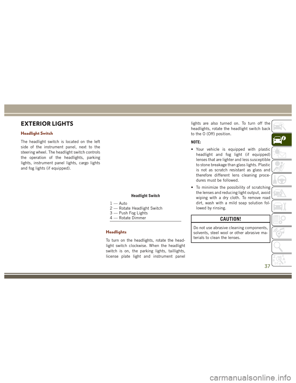
Headlight Switch
The headlight switch is located on the left
side of the instrument panel, next to the
steering wheel. The headlight switch controls
the operation of the headlights, parking
lights, instrument panel lights, cargo lights
and fog lights (if equipped).
Headlights
To turn on the headlights, rotate the head-
light switch clockwise. When the headlight
switch is on, the parking lights, taillights,
license plate light and instrument panellights are also turned on. To turn off the
headlights, rotate the headlight switch back
to the O (Off) position.
NOTE:
• Your vehicle is equipped with plastic
headlight and fog light (if equipped)
lenses that are lighter and less susceptible
to stone breakage than glass lights. Plastic
is not as scratch resistant as glass and
therefore different lens cleaning proce-
dures must be followed.
• To minimize the possibility of scratching the lenses and reducing light output, avoid
wiping with a dry cloth. To remove road
dirt, wash with a mild soap solution fol-
lowed by rinsing.
CAUTION!
Do not use abrasive cleaning components,
solvents, steel wool or other abrasive ma-
terials to clean the lenses.
Headlight Switch
1 — Auto
2 — Rotate Headlight Switch
3 — Push Fog Lights
4 — Rotate Dimmer
37
Page 41 of 372
If the windshield or Automatic High Beam
Headlamp Control mirror is replaced, the
mirror must be re-aimed to ensure proper
performance. See your local authorized
dealer.
Parking Lights And Panel Lights
To turn on the parking lights and instrument
panel lights, rotate the headlight switch
clockwise. To turn off the parking lights,
rotate the headlight switch back to the O (Off)
position.
Headlight Delay
To aid in your exit, your vehicle is equipped
with a headlight delay that will leave the
headlights on for approximately up to 90 sec-
onds. This delay is initiated when the ignition
is turned OFF while the headlight switch is
on, and then the headlight switch is cycled
off. Headlight delay can be cancelled by
either turning the headlight switch on then
off, or by turning the ignition ON.NOTE:
This feature can be programmed through the
Uconnect system. Refer to “Uconnect Set-
tings” in “Multimedia” for further informa-
tion.
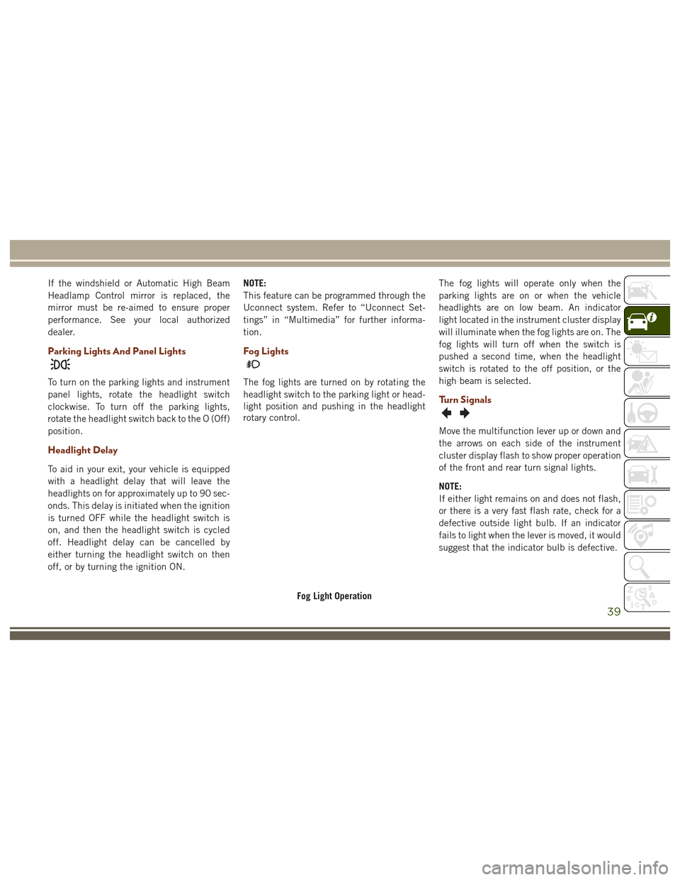
Fog Lights
The fog lights are turned on by rotating the
headlight switch to the parking light or head-
light position and pushing in the headlight
rotary control.
The fog lights will operate only when the
parking lights are on or when the vehicle
headlights are on low beam. An indicator
light located in the instrument cluster display
will illuminate when the fog lights are on. The
fog lights will turn off when the switch is
pushed a second time, when the headlight
switch is rotated to the off position, or the
high beam is selected.
Turn Signals
Move the multifunction lever up or down and
the arrows on each side of the instrument
cluster display flash to show proper operation
of the front and rear turn signal lights.
NOTE:
If either light remains on and does not flash,
or there is a very fast flash rate, check for a
defective outside light bulb. If an indicator
fails to light when the lever is moved, it would
suggest that the indicator bulb is defective.
Fog Light Operation
39
Page 50 of 372
IconDescription
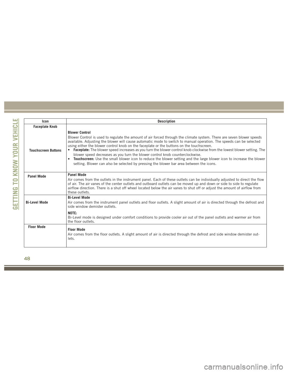
Faceplate Knob
Touchscreen Buttons
Blower Control
Blower Control is used to regulate the amount of air forced through the climate system. There are seven blower speeds
available. Adjusting the blower will cause automatic mode to switch to manual operation. The speeds can be selected
using either the blower control knob on the faceplate or the buttons on the touchscreen.
• Faceplate: The blower speed increases as you turn the blower control knob clockwise from the lowest blower setting. The
blower speed decreases as you turn the blower control knob counterclockwise.
• Touchscreen:
Use the small blower icon to reduce the blower setting and the large blower icon to increase the blower
setting. Blower can also be selected by pressing the blower bar area between the icons.
Panel Mode
Panel Mode
Air comes from the outlets in the instrument panel. Each of these outlets can be individually adjusted to direct the flow
of air. The air vanes of the center outlets and outboard outlets can be moved up and down or side to side to regulate
airflow direction. There is a shut off wheel located below the air vanes to shut off or adjust the amount of airflow from
these outlets.
Bi-Level Mode
Bi-Level Mode
Air comes from the instrument panel outlets and floor outlets. A slight amount of air is directed through the defrost and
side window demister outlets.
NOTE:
Bi-Level mode is designed under comfort conditions to provide cooler air out of the panel outlets and warmer air from
the floor outlets.
Floor Mode
Floor Mode
Air comes from the floor outlets. A slight amount of air is directed through the defrost and side window demister out-
lets.
GETTING TO KNOW YOUR VEHICLE
48
Page 197 of 372
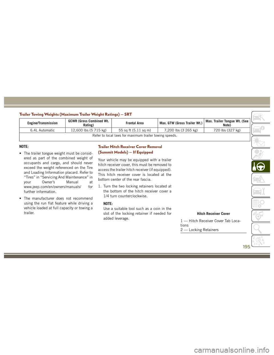
Trailer Towing Weights (Maximum Trailer Weight Ratings) — SRT
Engine/TransmissionGCWR (Gross Combined Wt.
Rating) Frontal Area Max. GTW (Gross Trailer Wt.) Max. Trailer Tongue Wt. (See
Note)
6.4L Automatic 12,600 lbs (5 715 kg) 55 sq ft (5.11 sq m) 7,200 lbs (3 265 kg) 720 lbs (327 kg) Refer to local laws for maximum trailer towing speeds.
NOTE:
• The trailer tongue weight must be consid-ered as part of the combined weight of
occupants and cargo, and should never
exceed the weight referenced on the Tire
and Loading Information placard. Refer to
“Tires” in “Servicing And Maintenance” in
your Owner’s Manual at
www.jeep.com/en/owners/manuals/ for
further information.
• The manufacturer does not recommend using the run flat feature while driving a
vehicle loaded at full capacity or towing a
trailer.Trailer Hitch Receiver Cover Removal
(Summit Models) — If Equipped
Your vehicle may be equipped with a trailer
hitch receiver cover, this must be removed to
access the trailer hitch receiver (if equipped).
This hitch receiver cover is located at the
bottom center of the rear fascia.
1. Turn the two locking retainers located at
the bottom of the hitch receiver cover a
1/4 turn counterclockwise.
NOTE:
Use a suitable tool such as a coin in the
slot of the locking retainer if needed for
added leverage.
Hitch Receiver Cover
1 — Hitch Receiver Cover Tab Loca-
tions
2 — Locking Retainers
195
Page 198 of 372
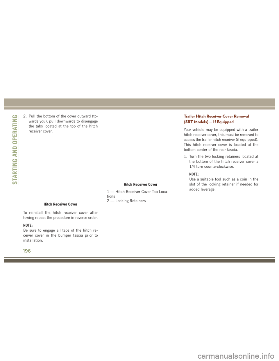
2. Pull the bottom of the cover outward (to-wards you), pull downwards to disengage
the tabs located at the top of the hitch
receiver cover.
To reinstall the hitch receiver cover after
towing repeat the procedure in reverse order.
NOTE:
Be sure to engage all tabs of the hitch re-
ceiver cover in the bumper fascia prior to
installation.Trailer Hitch Receiver Cover Removal
(SRT Models) — If Equipped
Your vehicle may be equipped with a trailer
hitch receiver cover, this must be removed to
access the trailer hitch receiver (if equipped).
This hitch receiver cover is located at the
bottom center of the rear fascia.
1. Turn the two locking retainers located at the bottom of the hitch receiver cover a
1/4 turn counterclockwise.
NOTE:
Use a suitable tool such as a coin in the
slot of the locking retainer if needed for
added leverage.
Hitch Receiver Cover
Hitch Receiver Cover
1 — Hitch Receiver Cover Tab Loca-
tions
2 — Locking Retainers
STARTING AND OPERATING
196
Page 208 of 372
Bulb Replacement
High Intensity Discharge Headlamps (HID)
—
If Equipped
The headlamps are a type of high voltage
discharge tube. High voltage can remain in
the circuit even with the headlamp switch off
and the key removed. Because of this, you
should not attempt to service a headlamp bulb
yourself. If a headlamp bulb fails, take your
vehicle to an authorized dealer for service.
WARNING!
A transient high voltage occurs at the bulb
sockets of High Intensity Discharge (HID)
headlamps when the headlamp switch is
turned ON. It may cause serious electrical
shock or electrocution if not serviced prop-
erly. See your authorized dealer for ser-
vice. NOTE:
On vehicles equipped with High Intensity
Discharge (HID) headlamps, when the head-
lamps are turned on, there is a blue hue to
the lamps. This diminishes and becomes
more white after approximately 10 seconds,
as the system charges.
Halogen Headlamps — If Equipped
1. Open the hood.
2. Turn the low or high beam bulb one–
quarter turn counterclockwise to remove
from housing.
3. Disconnect the electrical connector and replace the bulb.
CAUTION!
Do not touch the new bulb with your fin-
gers. Oil contamination will severely
shorten bulb life. If the bulb comes in
contact with any oily surface, clean the
bulb with rubbing alcohol.
Front Turn Signal Lamp
1. Open the hood.
2. Turn the turn signal bulb one–quarter turncounterclockwise to remove from
housing.
3. Disconnect the electrical connector and replace the bulb.
CAUTION!
Do not touch the new bulb with your fin-
gers. Oil contamination will severely
shorten bulb life. If the bulb comes in
contact with any oily surface, clean the
bulb with rubbing alcohol.
Front Fog Lamps
1. Reach through the cutout in the splashshield and disconnect the wiring harness
from the fog lamp connector.
2. Firmly grasp the bulb by the two latches and squeeze them together to unlock the
bulb from the back of the front fog lamp
housing.
IN CASE OF EMERGENCY
206
Page 209 of 372
3. Pull the bulb straight out from the keyedopening in the housing.
CAUTION!
•Do not touch the new bulb with your
fingers. Oil contamination will severely
shorten bulb life. If the bulb comes in
contact with any oily surface, clean the
bulb with rubbing alcohol.
• Always use the correct bulb size and type for replacement. An incorrect bulb size
or type may overheat and cause damage
to the lamp, the socket or the lamp
wiring.
4. Align the index tabs of the front fog lamp bulb with the slots in the collar of the bulb
opening on the back of the front fog lamp
housing.
5. Insert the bulb into the housing until the index tabs are engaged in the slots of the
collar.
6. Firmly and evenly push the bulb straight into the lamp housing until both tabs snap
firmly into place and are fully engaged. 7. Connect the wiring harness to the front fog
lamp connector.
Rear Tail, Stop, and Turn Signal Lamps
1. Raise the liftgate.
2. Remove the two push-pins from the taillamp housing.
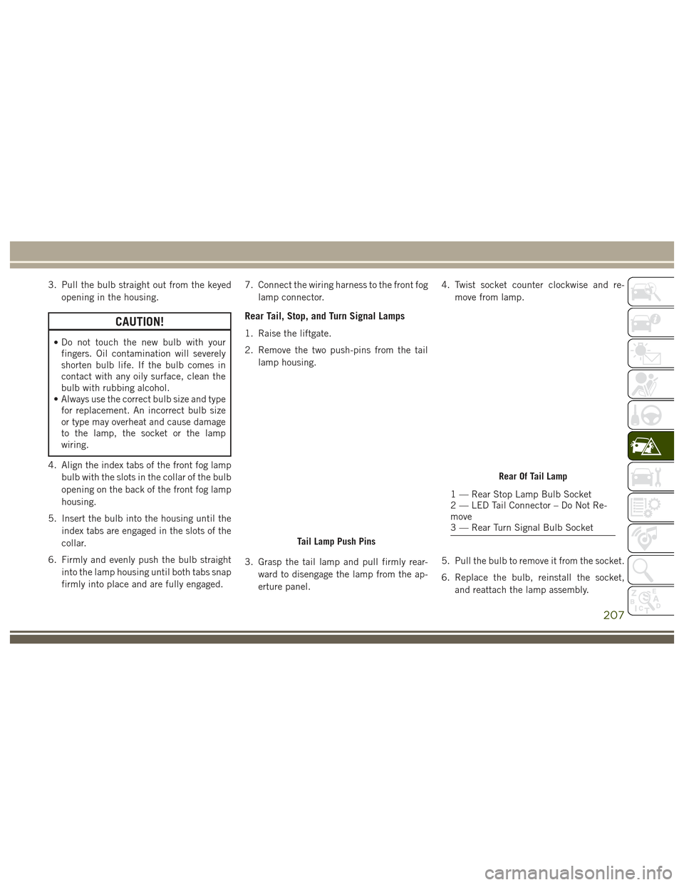
3. Grasp the tail lamp and pull firmly rear- ward to disengage the lamp from the ap-
erture panel. 4. Twist socket counter clockwise and re-
move from lamp.
5. Pull the bulb to remove it from the socket.
6. Replace the bulb, reinstall the socket, and reattach the lamp assembly.
Tail Lamp Push Pins
Rear Of Tail Lamp
1 — Rear Stop Lamp Bulb Socket
2 — LED Tail Connector – Do Not Re-
move
3 — Rear Turn Signal Bulb Socket
207
Page 210 of 372
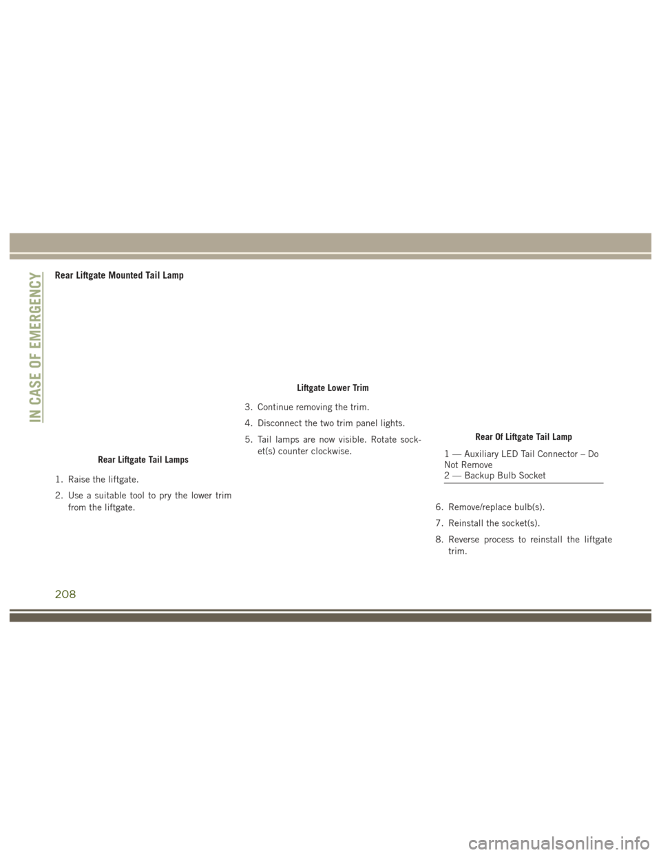
Rear Liftgate Mounted Tail Lamp
1. Raise the liftgate.
2. Use a suitable tool to pry the lower trimfrom the liftgate. 3. Continue removing the trim.
4. Disconnect the two trim panel lights.
5. Tail lamps are now visible. Rotate sock-
et(s) counter clockwise.
6. Remove/replace bulb(s).
7. Reinstall the socket(s).
8. Reverse process to reinstall the liftgatetrim.
Rear Liftgate Tail Lamps
Liftgate Lower Trim
Rear Of Liftgate Tail Lamp
1 — Auxiliary LED Tail Connector – Do
Not Remove
2 — Backup Bulb Socket
IN CASE OF EMERGENCY
208
Page 221 of 372
5. For a rear tire, place the jack in the slot onthe rear tie-down bracket, just forward of
the rear tire (as indicated by the triangular
lift point symbol on the sill molding). Do
not raise the vehicle until you are sure the
jack is fully engaged. 6. Raise the vehicle by turning the jack
screw clockwise. Raise the vehicle only
until the tire just clears the surface and
enough clearance is obtained to install
the spare tire. Minimum tire lift provides
maximum stability.
WARNING!
Raising the vehicle higher than necessary
can make the vehicle less stable. It could
WARNING!
slip off the jack and hurt someone near it.
Raise the vehicle only enough to remove
the tire.
7. Remove the lug nuts and wheel.
8. Position the spare wheel/tire on the ve- hicle and install the lug nuts with the
cone-shaped end toward the wheel.
Lightly tighten the nuts.
WARNING!
To avoid the risk of forcing the vehicle off
the jack, do not tighten the lug nuts fully
until the vehicle has been lowered. Failure
to follow this warning may result in serious
injury.Front Jacking LocationRear Jacking Location
219
Page 222 of 372
CAUTION!
Be sure to mount the spare tire with the
valve stem facing outward. The vehicle
could be damaged if the spare tire is
mounted incorrectly.
9. Lower the vehicle by turning the jack screw counterclockwise, and remove the
jack and wheel blocks. 10. Finish tightening the lug nuts. Push
down on the wrench while at the end of
the handle for increased leverage.
Tighten the lug nuts in a star pattern
until each nut has been tightened twice.
The correct tightness of each lug nut is
130 ft-lbs (176 N·m). If in doubt about
the correct tightness, have them
checked with a torque wrench by your
authorized dealer or service station.
NOTE:
For the SRT model the correct wheel nut
tightness is 110 ft lbs (149 N·m).
11. Lower the jack to the fully closed posi- tion and return it and the tools to the
proper positions in the foam tray.
12. Remove the small center cap and se- curely store the road wheel in the cargo
area. 13. Have the aluminum road wheel and tire
repaired as soon as possible, properly
secure the spare tire with the special
wing nut torqued to 3.7 ft-lbs (5 N·m),
reinstall the jack and tool kit foam tray,
and latch the rear load floor cover.
NOTE:
Do not drive with the spare tire installed for
more than 50 miles (80 km) at a max speed
of 50 mph (80 km/h).
Installing Spare Wheel/Tire
Spare Tire
IN CASE OF EMERGENCY
220