sensor JEEP GRAND CHEROKEE 2018 Owner handbook (in English)
[x] Cancel search | Manufacturer: JEEP, Model Year: 2018, Model line: GRAND CHEROKEE, Model: JEEP GRAND CHEROKEE 2018Pages: 368, PDF Size: 5.72 MB
Page 173 of 368
the system is disabled, the instrument clus-
ter display will show the “PARKSENSE OFF”
message for as long as the vehicle is in
REVERSE.
The ParkSense switch LED will be on when
ParkSense is disabled or requires service.
The ParkSense switch LED will be off when
the system is enabled. If the ParkSense
switch is pushed, and the system requires
service, the ParkSense switch LED will blink
momentarily, and then the LED will be on.
Instrument Cluster Display
The ParkSense Warning screen will only be
displayed if Sound and Display is selected
from the Customer - Programmable Features
section of the Uconnect System. Refer to
“Uconnect Settings” in “Multimedia” in the
Owner’s Manual for further information.
The ParkSense Warning screen is located
within the instrument cluster display. It pro-
vides visual warnings to indicate the distance
between the rear fascia/bumper and the de-tected obstacle. Refer to “Instrument Cluster
Display” in “Getting To Know Your Instru-
ment Panel” in the Owner’s Manual for fur-
ther information.
ParkSense System Usage Precautions
NOTE:
• Ensure that the rear bumper is free of snow,
ice, mud, dirt and debris to keep the
ParkSense system operating properly.
• Jackhammers, large trucks, and other vi-
brations could affect the performance of
ParkSense.
• When you turn ParkSense off, the instru-
ment cluster display will read
“PARKSENSE OFF”. Furthermore, once
you turn ParkSense off, it remains off until
you turn it on again, even if you cycle the
ignition.
• When you move the gear selector to the
REVERSE position and ParkSense is turned
off, the instrument cluster display will show
a “PARKSENSE OFF” message for as long
as the vehicle is in REVERSE.• ParkSense, when on, will reduce the vol-
ume of the radio when it is sounding a tone.
• Clean the ParkSense sensors regularly, tak-
ing care not to scratch or damage them. The
sensors must not be covered with ice, snow,
slush, mud, dirt or debris. Failure to do so
can result in the system not working prop-
erly. The ParkSense system might not de-
tect an obstacle behind the fascia/bumper,
or it could provide a false indication that an
obstacle is behind the fascia/bumper.
• Use the ParkSense switch to turn the
ParkSense system OFF if objects such as
bicycle carriers, trailer hitches, etc. are
placed within 12 inches (30 cm) from the
rear fascia/bumper. Failure to do so can
result in the system misinterpreting a close
object as a sensor problem, causing the
“PARKSENSE UNAVAILABLE SERVICE
REQUIRED” message to appear in the in-
strument cluster display.
• ParkSense should be disabled when the
liftgate is in the open position and the
vehicle is in REVERSE. An open liftgate
could provide a false indication that an
obstacle is behind the vehicle.
171
Page 174 of 368
WARNING!
• Drivers must be careful when backing up
even when using ParkSense. Always
check carefully behind your vehicle,
look behind you, and be sure to check
for pedestrians, animals, other vehicles,
obstructions, and blind spots before
backing up. You are responsible for
safety and must continue to pay atten-
tion to your surroundings. Failure to do
so can result in serious injury or death.
• Before using ParkSense, it is strongly
recommended that the ball mount and
hitch ball assembly is disconnected
from the vehicle when the vehicle is not
used for towing. Failure to do so can
result in injury or damage to vehicles or
obstacles because the hitch ball will be
much closer to the obstacle than the
rear fascia when the loudspeaker sounds
the continuous tone. Also, the sensors
could detect the ball mount and hitch
ball assembly, depending on its size and
shape, giving a false indication that an
obstacle is behind the vehicle.
CAUTION!
• ParkSense is only a parking aid and it is
unable to recognize every obstacle, in-
cluding small obstacles. Parking curbs
might be temporarily detected or not
detected at all. Obstacles located above
or below the sensors will not be detected
when they are in close proximity.
• The vehicle must be driven slowly when
using ParkSense in order to be able to
stop in time when an obstacle is de-
tected. It is recommended that the
driver looks over his/her shoulder when
using ParkSense.
PARKSENSE FRONT AND
REAR PARK ASSIST
ParkSense Sensors
The four ParkSense sensors, located in the
rear fascia/bumper, monitor the area behind
the vehicle that is within the sensors field of
view. The sensors can detect obstacles from
approximately 12 inches (30 cm) up to79 inches (200 cm) from the rear fascia/
bumper in the horizontal direction, depend-
ing on the location, type and orientation of
the obstacle.
The six ParkSense sensors, located in the
front fascia/bumper, monitor the area in front
of the vehicle that is within the sensors’ field
of view. The sensors can detect obstacles
from approximately 12 inches (30 cm) up to
47 inches (120 cm) from the front fascia/
bumper in the horizontal direction, depend-
ing on the location, type and orientation of
the obstacle.
When an object is detected within 79 inches
(200 cm) behind the rear bumper while the
vehicle is in REVERSE, a warning will appear
in the instrument cluster display. In addition
a chime will sound (when Sound and Display
is selected from the Customer Programmable
Features section of the Uconnect System
screen). As the vehicle moves closer to the
object, the chime rate will change from single
1/2 second tone (for rear only), to slow (for
rear only), to fast, to continuous.
STARTING AND OPERATING
172
Page 175 of 368
Activation/Deactivation
The ParkSense Park Assist system provides
visual and audible indications of the distance
between the rear and/or front fascia and a
detected obstacle when backing up or moving
forward, e.g. during a parking maneuver. If
your vehicle is equipped with an Automatic
Transmission, the vehicle brakes may be au-
tomatically applied and released when per-
forming a reverse parking maneuver if the
system detects a possible collision with an
obstacle.
ParkSense can be active only when the gear
selector is in REVERSE or DRIVE. If
ParkSense is enabled at one of these gear
selector positions, the system will remain
active until the vehicle speed is increased to
approximately 7 mph (11 km/h) or above. A
display warning will appear in the instrument
cluster display indicating the vehicle is aboveParkSense operating speed. The system will
become active again if the vehicle speed is
decreased to speeds less than approximately
6 mph (9 km/h).
Engagement/Disengagement
To disengage the system, push the ParkSense
switch, located on the switch panel below the
Uconnect display.
When the system passes from engaged to
disengaged and vice versa, it is always ac-
companied by a dedicated message in the
instrument cluster display.
System engaged:ParkSense switch LED off.
System disengaged:ParkSense switch LED on
constantly.
The ParkSense switch LED lights up also in
the case of a ParkSense system failure. If the
button is pushed with a system failure, the
ParkSense switch LED flashes for about five
seconds, then it stays on constantly.After the ParkSense has been disengaged, it
will stay in this condition until the following
engagement, even if the ignition device
passes from ON/RUN to OFF and then again
to ON/RUN.Operation With A Trailer
The operation of the sensors is automatically
deactivated when the trailer's electric plug is
inserted in the vehicle's tow hook socket. The
sensors are automatically reactivated when
the trailer's cable plug is removed.
General Warnings
If “PARKSENSE UNAVAILABLE WIPE REAR
SENSORS" or "PARKSENSE UNAVAILABLE
WIPE FRONT SENSORS” appears in the in-
strument cluster display, clean the
ParkSense sensors with water, car wash soap
and a soft cloth. Do not use rough or hard
cloths. Do not scratch or poke the sensors.
Otherwise, you could damage the sensors.
173
Page 176 of 368
PARKSENSE ACTIVE PARK
ASSIST SYSTEM — IF
EQUIPPED
The ParkSense Active Park Assist system is
intended to assist the driver during parallel
and perpendicular parking maneuvers by
identifying a proper parking space, providing
audible/visual instructions, and controlling
the steering wheel. The ParkSense Active
Park Assist system is defined as “semi-
automatic” since the driver maintains control
of the accelerator, gear selector and brakes.
Depending on the driver's parking maneuver
selection, the ParkSense Active Park Assist
system is capable of maneuvering a vehicle
into a parallel or a perpendicular parking
space on either side (i.e., driver side or pas-
senger side).
NOTE:
• The driver is always responsible for control-
ling the vehicle, responsible for any sur-
rounding objects, and must intervene as
required.• The system is provided to assist the driver
and not to substitute the driver.
• During a semi-automatic maneuver, if the
driver touches the steering wheel after be-
ing instructed to remove their hands from
the steering wheel, the system will cancel,
and the driver will be required to manually
complete the parking maneuver.
• The system may not work in all conditions
(e.g. environmental conditions such as
heavy rain, snow, etc., or if searching for a
parking space that has surfaces that will
absorb the ultrasonic sensor waves).
• New vehicles from the dealership must
have at least 30 miles (48 km) accumu-
lated before the ParkSense Active Park
Assist system is fully calibrated and per-
forms accurately. This is due to the sys-
tem’s dynamic vehicle calibration to im-
prove the performance of the feature. The
system will also continuously perform the
dynamic vehicle calibration to account for
differences such as over or under inflated
tires and new tires.Enabling And Disabling The ParkSense Active
Park Assist System
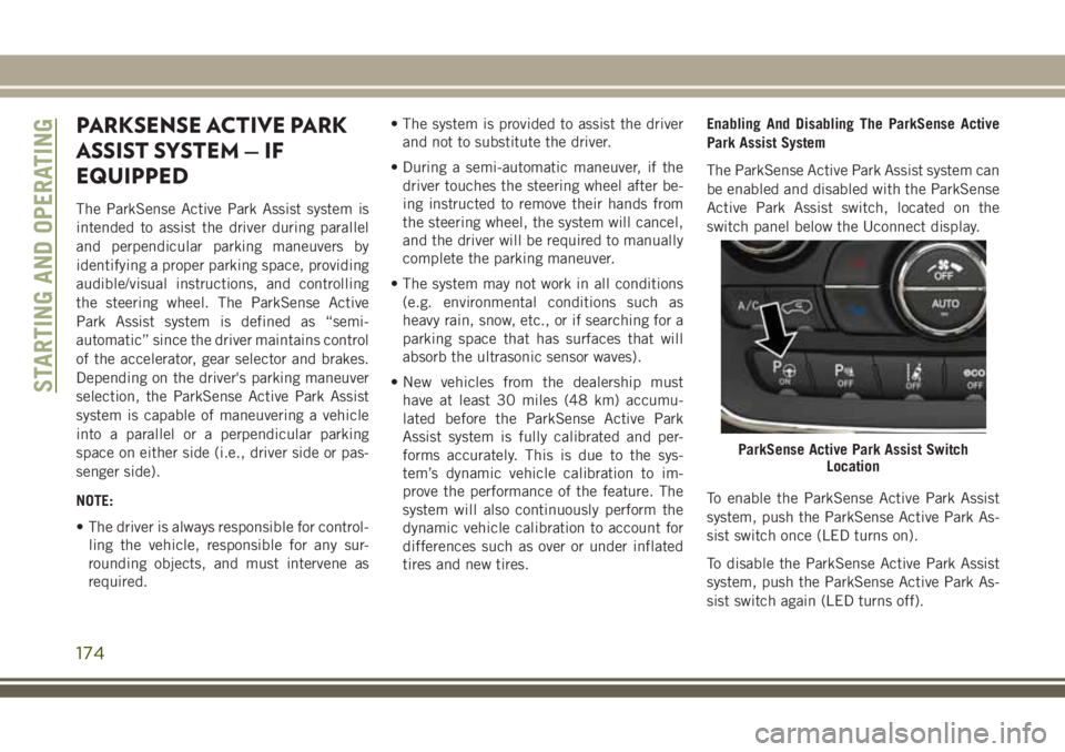
The ParkSense Active Park Assist system can
be enabled and disabled with the ParkSense
Active Park Assist switch, located on the
switch panel below the Uconnect display.
To enable the ParkSense Active Park Assist
system, push the ParkSense Active Park As-
sist switch once (LED turns on).
To disable the ParkSense Active Park Assist
system, push the ParkSense Active Park As-
sist switch again (LED turns off).
ParkSense Active Park Assist Switch
Location
STARTING AND OPERATING
174
Page 184 of 368
System Overview
This vehicle is equipped with a Diesel Ex-
haust Fluid (DEF) injection system and a
Selective Catalytic Reduction (SCR) catalyst
to meet the emission requirements.
The DEF injection system consists of the
following components:
• DEF tank
• DEF pump
• DEF injector
• Electronically-heated DEF lines
• NOx sensors
• Temperature sensors
• SCR catalyst
The DEF injection system and SCR catalyst
enable the achievement of diesel emissions
requirements; while maintaining outstanding
fuel economy, drivability, torque and power
ratings.Refer to “Instrument Cluster Display” in
“Getting To Know Your Instrument Panel” for
system messages and warnings.
NOTE:
• Your vehicle is equipped with a DEF injec-
tion system. You may occasionally hear an
audible clicking noise from under the ve-
hicle at a stop. This is normal operation.
• The DEF pump will run for a period of time
after engine shutdown to purge the DEF
system. This is normal operation and may
be audible from the rear of the vehicle.
Diesel Exhaust Fluid Storage
Diesel Exhaust Fluid (DEF) is considered a
very stable product with a long shelf life. If
DEF is kept in temperatures between 10° and
90°F (-12° and 32°C), it will last a minimum
of one year.
DEF is subject to freezing at the lowest tem-
peratures. For example, DEF may freeze at
temperatures at or below 12° F (-11° C). The
system has been designed to operate in this
environment.
NOTE:
When working with DEF, it is important to
know that:
• Any containers or parts that come into con-
tact with DEF must be DEF compatible
(plastic or stainless steel). Copper, brass,
aluminum, iron or non-stainless steel
should be avoided as they are subject to
corrosion by DEF.
• If DEF is spilled, it should be wiped up
completely.
STARTING AND OPERATING
182
Page 208 of 368
Cavity Cartridge Fuse Micro Fuse Description
F32 30 Amp Pink – Drive Train Control Module
F34 30 Amp Pink – Slip Differential Control
F35 30 Amp Pink – Sunroof - If Equipped
F36 30 Amp Pink – Rear Defroster
F37 25 Amp Clear – Rear Blower Motor — If Equipped
F38 30 Amp Pink – Power Inverter 115V AC — If Equipped
F39 30 Amp Pink – Power Liftgate — If Equipped
F40 – 10 Amp Red Daytime Running Lights/Headlamp Leveling
F42 – 20 Amp Yellow Horn
F44 – 10 Amp Red Diagnostic Port
F45 – 5 Amp Tan Cyber Security Gateway
F49 – 10 Amp Red Integrated Central Stack/Climate Control
F50 – 20 Amp Yellow Air Suspension Control Module/Slip Differential - If
Equipped
F51 – 15 Amp Blue Ignition Node Module/Keyless Ignition/Steering Column
Lock
F53 – 20 Amp Yellow Trailer Tow – Left Turn/Stop Lights — If Equipped
F56 – 15 Amp Blue Additional Content (Diesel engine only)
F57 – 20 Amp Yellow NOX Sensor
F58 – 15 Amp Blue HID Headlamps LH — If Equipped
F59 – 10 Amp Red Purging Pump (Diesel engine only)
F60 – 15 Amp Blue Transmission Control Module
F61 – 10 Amp Red Transmission Control Module/PM Sensor (Diesel engine
only)
IN CASE OF EMERGENCY
206
Page 209 of 368
Cavity Cartridge Fuse Micro Fuse Description
F62 – 10 Amp Red Air Conditioning Clutch
F63 – 20 Amp Yellow Ignition Coils (Gas), Urea Heater (Diesel)
F64 – 25 Amp Clear Fuel Injectors/Powertrain
F66 – 10 Amp Red Sunroof/Passenger Window Switches/Rain Sensor
F67 – 15 Amp Blue CD/DVD/Bluetooth Hands-free Module — If Equipped
F68 – 20 Amp Yellow Rear Wiper Motor
F69 – 15 Amp Blue Spotlight Feed — If Equipped
F70 – 20 Amp Yellow Fuel Pump Motor
F71 – 30 Amp Green Audio Amplifier
F72 – 10 Amp Red PCM — If Equipped
F73 – 15 Amp Blue HID Headlamp RH — If Equipped
F75 – 10 Amp Red Dual Batt Control — If Equipped
F76 – 10 Amp Red Anti-lock Brakes/Electronic Stability Control
F77 – 10 Amp Red Drivetrain Control Module/Front Axle Disconnect Module
F78 – 10 Amp Red Engine Control Module/Electric Power Steering
F80 – 10 Amp Red Universal Garage Door Opener/Anti-Intrusion Module
F81 – 20 Amp Yellow Trailer Tow Right Turn/Stop Lights
F82 – 10 Amp Red Steering Column Control Module/Cruise Control/DTV
F83 – 10 Amp Red Fuel Door
F84 – 15 Amp Blue Switch Bank/Instrument Cluster
F85 – 10 Amp Red Airbag Module
F86 – 10 Amp Red Airbag Module
F87 – 10 Amp Red Air Suspension — If Equipped
207
Page 249 of 368
Checking Oil Level — Gasoline Engine
To assure proper lubrication of your vehicle’s
engine, the engine oil must be maintained at
the correct level. Check the oil level at regular
intervals, such as every fuel stop. The best
time to check the engine oil level is about five
minutes after a fully warmed up engine is
shut off.
Checking the oil while the vehicle is on level
ground will improve the accuracy of the oil
level readings. Always maintain the oil level
within the SAFE zone on the dipstick. Adding
one quart of oil when the reading is at the
bottom of the SAFE zone will result in a
reading at the top of the safe zone on these
engines.
CAUTION!
Overfilling or underfilling the crankcase
will cause aeration or loss of oil pressure.
This could damage your engine.
Checking Oil Level — 3.0 Diesel Engine
To assure proper lubrication of your vehicle's
engine, the engine oil must be maintained at
the correct level. Check the oil level at regular
intervals. The best time to check the oil level
is before starting the engine after it has been
parked overnight. When checking oil after
operating the engine, first ensure the engine
is at full operating temperature, then wait for
five minutes after engine shutdown to check
the oil.
Checking the oil while the vehicle is on level
ground will improve the accuracy of the oil
level readings. Add oil only when the level on
the dipstick is below the “MIN” mark. The
total capacity from the MIN mark to the MAX
mark is 1 qt (1 L).
CAUTION!
Overfilling or underfilling the crankcase
will cause oil aeration or loss of oil pres-
sure. This could damage your engine.NOTE:
It is possible for your oil level to be slightly
higher than a previous check. This would be
due to diesel fuel that may temporarily be in
the crankcase due to operation of the diesel
particulate filter regeneration strategy. This
fuel will evaporate out under normal opera-
tion.
Never operate the engine with oil level below
the “MIN” mark or above the upper “MAX”
mark.
Adding Washer Fluid
The instrument cluster display will indicate
when the washer fluid level is low. When the
sensor detects a low fluid level, the wind-
shield will light on the vehicle graphic outline
and the “WASHER FLUID LOW” message
will be displayed.
The fluid reservoir for the windshield washers
and the rear window washer is shared. The
fluid reservoir is located in the engine com-
partment, be sure to check the fluid level at
regular intervals. Fill the reservoir with wind-
shield washer solvent only (not radiator anti-
freeze). When refilling the washer fluid reser-
247
Page 286 of 368
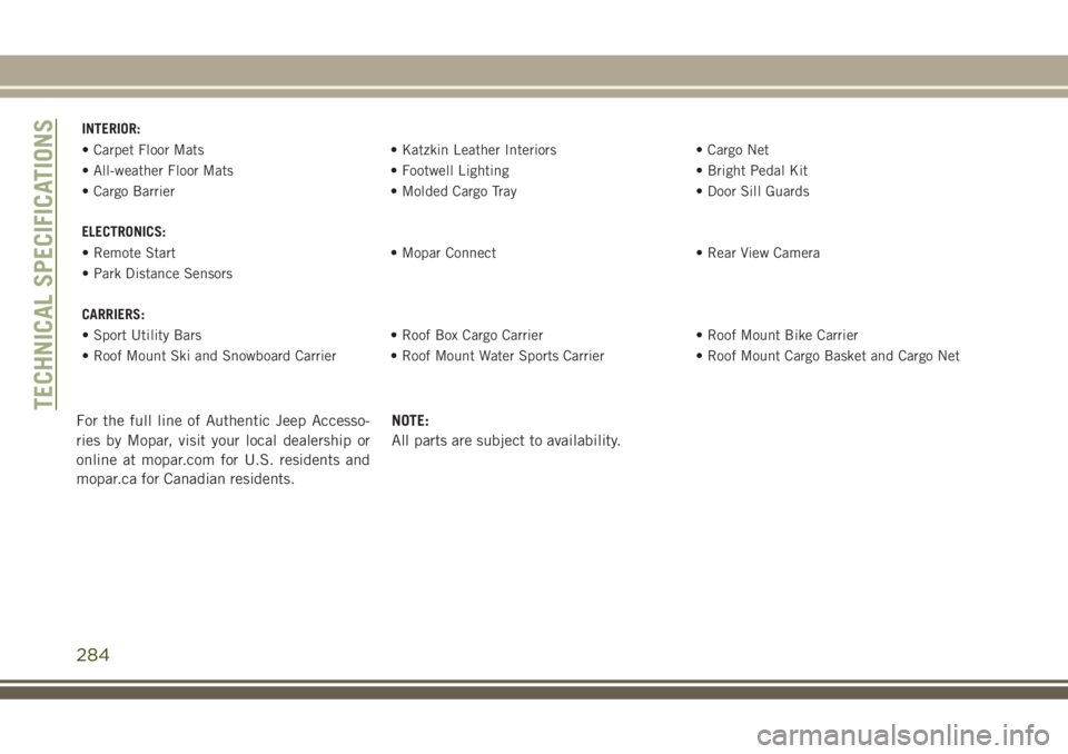
INTERIOR:
• Carpet Floor Mats • Katzkin Leather Interiors • Cargo Net
• All-weather Floor Mats • Footwell Lighting • Bright Pedal Kit
• Cargo Barrier • Molded Cargo Tray • Door Sill Guards
ELECTRONICS:
• Remote Start • Mopar Connect • Rear View Camera
• Park Distance Sensors
CARRIERS:
• Sport Utility Bars • Roof Box Cargo Carrier • Roof Mount Bike Carrier
• Roof Mount Ski and Snowboard Carrier • Roof Mount Water Sports Carrier • Roof Mount Cargo Basket and Cargo Net
For the full line of Authentic Jeep Accesso-
ries by Mopar, visit your local dealership or
online at mopar.com for U.S. residents and
mopar.ca for Canadian residents.NOTE:
All parts are subject to availability.TECHNICAL SPECIFICATIONS
284