air condition JEEP GRAND CHEROKEE 2020 Owner handbook (in English)
[x] Cancel search | Manufacturer: JEEP, Model Year: 2020, Model line: GRAND CHEROKEE, Model: JEEP GRAND CHEROKEE 2020Pages: 378, PDF Size: 6.88 MB
Page 89 of 378
required. However, the conventional brake
system will continue to operate normally if
the “Anti-Lock Brake Warning Light” is on.
If the “Anti-Lock Brake Warning Light” is on,
the brake system should be serviced as soon
as possible to restore the benefits of anti-lock
brakes. If the “Anti-Lock Brake Warning
Light” does not come on when the ignition is
turned to the ON/RUN mode, have the light
repaired as soon as possible.
Electronic Brake Control System
Your vehicle is equipped with an advanced
Electronic Brake Control system (EBC). This
system includes Electronic Brake Force Dis-
tribution (EBD), Anti-Lock Brake System
(ABS), Brake Assist System (BAS), Hill Start
Assist (HSA), Traction Control System (TCS),
Electronic Stability Control (ESC), and Elec-
tronic Roll Mitigation (ERM). These systems
work together to enhance both vehicle stabil-
ity and control in various driving conditions.Your vehicle may also be equipped with
Trailer Sway Control (TSC), Ready Alert Brak-
ing (RAB), Rain Brake Support (RBS), Dy-
namic Steering Torque (DST), Hill Descent
Control (HDC), and Selec-Speed Control
(SSC).
Your vehicle may also be equipped with
Trailer Sway Control (TSC), Ready Alert Brak-
ing (RAB), Rain Brake Support (RBS), and-
Dynamic Steering Torque (DST).
Electronic Brake Force Distribution (EBD)
This function manages the distribution of the
braking torque between the front and rear
axles by limiting braking pressure to the rear
axle. This is done to prevent overslip of the
rear wheels to avoid vehicle instability, and to
prevent the rear axle from entering ABS be-
fore the front axle.
Brake System Warning Light
The red “Brake System Warning Light” will
turn on when the ignition is turned to the
ON/RUN mode and may stay on for as long as
four seconds.If the “Brake System Warning Light” remains
on or comes on while driving, it indicates that
the brake system is not functioning properly
and that immediate service is required. If the
“Brake System Warning Light” does not
come on when the ignition is turned to the
ON/RUN mode, have the light repaired as
soon as possible.
Brake Assist System (BAS)
The BAS is designed to optimize the vehicle’s
braking capability during emergency braking
maneuvers. The system detects an emer-
gency braking situation by sensing the rate
and amount of brake application and then
applies optimum pressure to the brakes. This
can help reduce braking distances. The BAS
complements the anti-lock brake system
(ABS). Applying the brakes very quickly re-
sults in the best BAS assistance. To receive
the benefit of the system, you must apply
continuous braking pressure during the stop-
ping sequence, (do not “pump” the brakes).
Do not reduce brake pedal pressure unless
braking is no longer desired. Once the brake
pedal is released, the BAS is deactivated.
87
Page 112 of 378
Lap/Shoulder Belts
All seating positions in your vehicle are
equipped with lap/shoulder belts.
The seat belt webbing retractor will lock only
during very sudden stops or collisions. This
feature allows the shoulder part of the seat
belt to move freely with you under normal
conditions. However, in a collision the seat
belt will lock and reduce your risk of striking
the inside of the vehicle or being thrown out
of the vehicle.
WARNING!
• Relying on the air bags alone could lead
to more severe injuries in a collision. The
air bags work with your seat belt to
restrain you properly. In some collisions,
the air bags won’t deploy at all. Always
wear your seat belt even though you have
air bags.
• In a collision, you and your passengers
can suffer much greater injuries if you
are not properly buckled up. You can
strike the interior of your vehicle or other
passengers, or you can be thrown out of
WARNING!
the vehicle. Always be sure you and
others in your vehicle are buckled up
properly.
• It is dangerous to ride in a cargo area,
inside or outside of a vehicle. In a colli-
sion, people riding in these areas are
more likely to be seriously injured or
killed.
• Do not allow people to ride in any area of
your vehicle that is not equipped with
seats and seat belts.
• Be sure everyone in your vehicle is in a
seat and using a seat belt properly. Oc-
cupants, including the driver, should al-
ways wear their seat belts whether or not
an air bag is also provided at their seat-
ing position to minimize the risk of se-
vere injury or death in the event of a
crash.
• Wearing your seat belt incorrectly could
make your injuries in a collision much
worse. You might suffer internal injuries,
or you could even slide out of the seat
belt. Follow these instructions to wear
WARNING!
your seat belt safely and to keep your
passengers safe, too.
• Two people should never be belted into a
single seat belt. People belted together
can crash into one another in a collision,
hurting one another badly. Never use a
lap/shoulder belt or a lap belt for more
than one person, no matter what their
size.
WARNING!
• A lap belt worn too high can increase the
risk of injury in a collision. The seat belt
forces won’t be at the strong hip and
pelvic bones, but across your abdomen.
Always wear the lap part of your seat belt
as low as possible and keep it snug.
• A twisted seat belt may not protect you
properly. In a collision, it could even cut
into you. Be sure the seat belt is flat
against your body, without twists. If you
can’t straighten a seat belt in your ve-
hicle, take it to an authorized dealer
immediately and have it fixed.
SAFETY
110
Page 120 of 378
designed to be maintenance free, if any of
the following occurs, have an authorized
dealer service the air bag system immedi-
ately.
• The Air Bag Warning Light does not come
on during the four to eight seconds when
the ignition switch is first in the ON/RUN
position.
• The Air Bag Warning Light remains on after
the four to eight-second interval.
• The Air Bag Warning Light comes on inter-
mittently or remains on while driving.
NOTE:
If the speedometer, tachometer, or any en-
gine related gauges are not working, the Oc-
cupant Restraint Controller (ORC) may also
be disabled. In this condition the air bags
may not be ready to inflate for your protec-
tion. Have an authorized dealer service the
air bag system immediately.
WARNING!
Ignoring the Air Bag Warning Light in your
instrument panel could mean you won’t
WARNING!
have the air bag system to protect you in a
collision. If the light does not come on as a
bulb check when the ignition is first
turned on, stays on after you start the
vehicle, or if it comes on as you drive, have
an authorized dealer service the air bag
system immediately.
Redundant Air Bag Warning Light
If a fault with the Air Bag Warning Light is
detected, which could affect the Supplemen-
tal Restraint System (SRS), the Redundant
Air Bag Warning Light will illuminate on the
instrument panel. The Redundant Air Bag
Warning Light will stay on until the fault is
cleared. In addition, a single chime will
sound to alert you that the Redundant Air Bag
Warning Light has come on and a fault has
been detected. If the Redundant Air Bag
Warning Light comes on intermittently or
remains on while driving have an authorized
dealer service the vehicle immediately.For additional information regarding the Re-
dundant Air Bag Warning Light refer to “Get-
ting To Know Your Instrument Panel” section
of this manual.
Front Air Bags
This vehicle has front air bags and lap/
shoulder belts for both the driver and front
passenger. The front air bags are a supple-
ment to the seat belt restraint systems. The
driver front air bag is mounted in the center
of the steering wheel. The passenger front air
bag is mounted in the instrument panel,
above the glove compartment. The words
“SRS AIRBAG” or “AIRBAG” are embossed
on the air bag covers.
SAFETY
118
Page 128 of 378
WARNING!
• It is dangerous to try to repair any part of
the air bag system yourself. Be sure to
tell anyone who works on your vehicle
that it has an air bag system.
• Do not attempt to modify any part of your
air bag system. The air bag may inflate
accidentally or may not function prop-
erly if modifications are made. Take your
vehicle to an authorized dealer for any
air bag system service. If your seat, in-
cluding your trim cover and cushion,
needs to be serviced in any way (includ-
ing removal or loosening/tightening of
seat attachment bolts), take the vehicle
to an authorized dealer. Only manufac-
turer approved seat accessories may be
used. If it is necessary to modify the air
bag system for persons with disabilities,
contact an authorized dealer.
Event Data Recorder (EDR)
This vehicle is equipped with an event data
recorder (EDR). The main purpose of an EDR
is to record, in certain crash or near crash-
like situations, such as an air bag deployment
or hitting a road obstacle, data that will assist
in understanding how a vehicle’s systems
performed. The EDR is designed to record
data related to vehicle dynamics and safety
systems for a short period of time, typically
30 seconds or less. The EDR in this vehicle is
designed to record such data as:
• How various systems in your vehicle were
operating;
• Whether or not the driver and passenger
safety belts were buckled/fastened;
• How far (if at all) the driver was depressing
the accelerator and/or brake pedal; and,
• How fast the vehicle was traveling.
These data can help provide a better under-
standing of the circumstances in which
crashes and injuries occur.NOTE:
EDR data are recorded by your vehicle only if
a non-trivial crash situation occurs; no data
are recorded by the EDR under normal driving
conditions and no personal data (e.g., name,
gender, age, and crash location) are re-
corded. However, other parties, such as law
enforcement, could combine the EDR data
with the type of personally identifying data
routinely acquired during a crash investiga-
tion.
To read data recorded by an EDR, special
equipment is required, and access to the
vehicle or the EDR is needed. In addition to
the vehicle manufacturer, other parties, such
as law enforcement, that have the special
equipment, can read the information if they
have access to the vehicle or the EDR.
SAFETY
126
Page 143 of 378
WARNING!
In a collision, people riding in these
areas are more likely to be seriously
injured or killed.
• Do not allow people to ride in any area of
your vehicle that is not equipped with
seats and seat belts.
• Be sure everyone in your vehicle is in a
seat and using a seat belt properly.
Exhaust Gas
WARNING!
Exhaust gases can injure or kill. They con-
tain carbon monoxide (CO), which is col-
orless and odorless. Breathing it can make
you unconscious and can eventually poi-
son you. To avoid breathing (CO), follow
these safety tips:
• Do not run the engine in a closed garage
or in confined areas any longer than
needed to move your vehicle in or out of
the area.
WARNING!
• If you are required to drive with the
trunk/liftgate/rear doors open, make sure
that all windows are closed and the cli-
mate control BLOWER switch is set at
high speed. DO NOT use the recircula-
tion mode.
• If it is necessary to sit in a parked vehicle
with the engine running, adjust your
heating or cooling controls to force out-
side air into the vehicle. Set the blower
at high speed.
The best protection against carbon monoxide
entry into the vehicle body is a properly main-
tained engine exhaust system.
Whenever a change is noticed in the sound of
the exhaust system, when exhaust fumes can
be detected inside the vehicle, or when the
underside or rear of the vehicle is damaged,
have a competent mechanic inspect the com-
plete exhaust system and adjacent body ar-
eas for broken, damaged, deteriorated, or
mispositioned parts. Open seams or loose
connections could permit exhaust fumes to
seep into the passenger compartment. Inaddition, inspect the exhaust system each
time the vehicle is raised for lubrication or oil
change. Replace as required.
Safety Checks You Should Make Inside
The Vehicle
Seat Belts
Inspect the seat belt system periodically,
checking for cuts, frays, and loose parts.
Damaged parts must be replaced immedi-
ately. Do not disassemble or modify the sys-
tem.
Front seat belt assemblies must be replaced
after a collision. Rear seat belt assemblies
must be replaced after a collision if they have
been damaged (i.e., bent retractor, torn web-
bing, etc.). If there is any question regarding
seat belt or retractor condition, replace the
seat belt.
Air Bag Warning Light
The Air Bag warning lightwill turn on for
four to eight seconds as a bulb check when
the ignition switch is first turned to ON/RUN.
If the light is either not on during starting,
stays on, or turns on while driving, have the
141
Page 158 of 378
placing the transmission in PARK. This sys-
tem also locks the transmission in PARK
whenever the ignition is in the OFF mode.
NOTE:
The transmission is NOT locked in PARK
when the ignition is in the ACC mode (even
though the engine will be off). Ensure that
the transmission is in PARK, and the ignition
isOFF(not in ACC mode) before exiting the
vehicle.
Brake/Transmission Shift Interlock
System
This vehicle is equipped with a Brake Trans-
mission Shift Interlock system (BTSI) that
holds the transmission gear selector in PARK
unless the brakes are applied. To shift the
transmission out of PARK, the engine must
be running and the brake pedal must be
pressed. The brake pedal must also be
pressed to shift from NEUTRAL into DRIVE or
REVERSE when the vehicle is stopped or
moving at low speeds.
Fuel Economy (ECO) Mode
The Fuel Economy (ECO) mode can improve
the vehicle's overall fuel economy during nor-
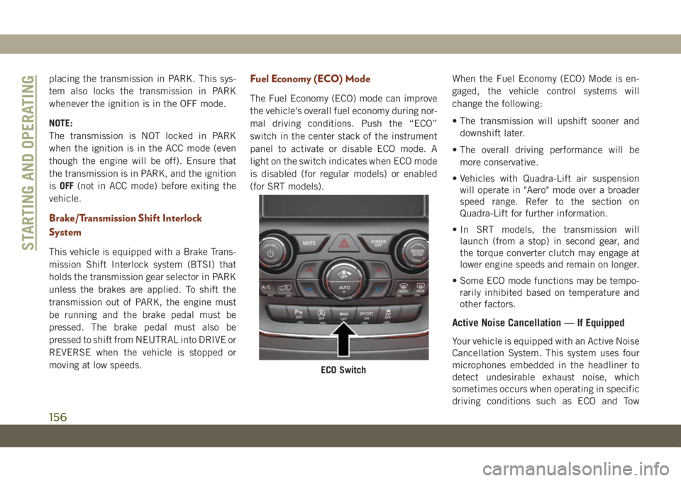
mal driving conditions. Push the “ECO”
switch in the center stack of the instrument
panel to activate or disable ECO mode. A
light on the switch indicates when ECO mode
is disabled (for regular models) or enabled
(for SRT models).When the Fuel Economy (ECO) Mode is en-
gaged, the vehicle control systems will
change the following:
• The transmission will upshift sooner and
downshift later.
• The overall driving performance will be
more conservative.
• Vehicles with Quadra-Lift air suspension
will operate in "Aero" mode over a broader
speed range. Refer to the section on
Quadra-Lift for further information.
• In SRT models, the transmission will
launch (from a stop) in second gear, and
the torque converter clutch may engage at
lower engine speeds and remain on longer.
• Some ECO mode functions may be tempo-
rarily inhibited based on temperature and
other factors.
Active Noise Cancellation — If Equipped
Your vehicle is equipped with an Active Noise
Cancellation System. This system uses four
microphones embedded in the headliner to
detect undesirable exhaust noise, which
sometimes occurs when operating in specific
driving conditions such as ECO and Tow
ECO Switch
STARTING AND OPERATING
156
Page 164 of 378
4. If vehicle is equipped with Quadra-Lift air
suspension, ensure the vehicle is set to
Normal Ride Height.
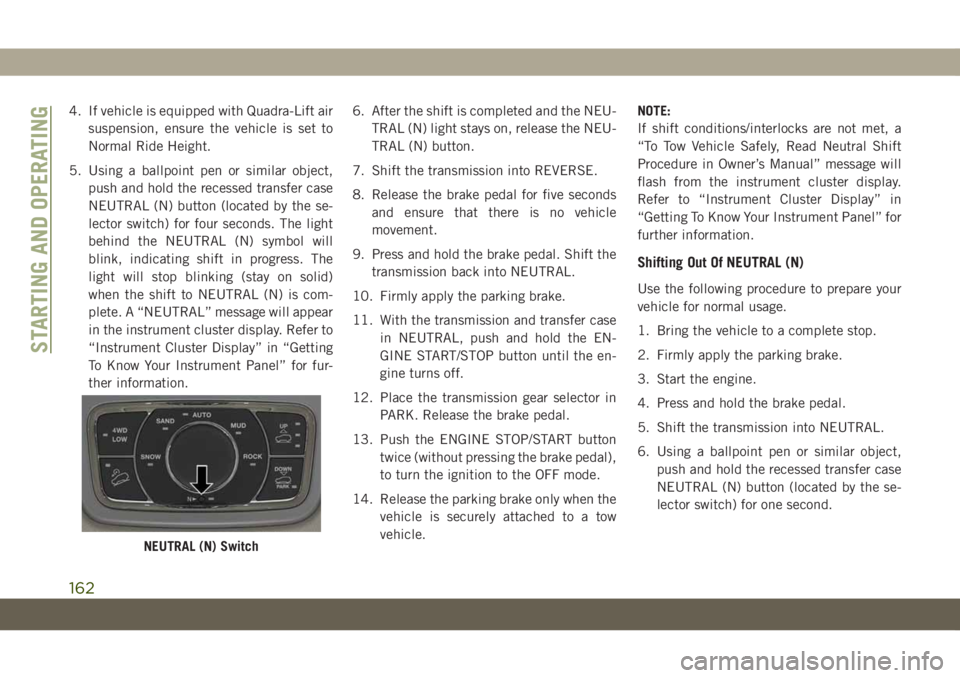
5. Using a ballpoint pen or similar object,
push and hold the recessed transfer case
NEUTRAL (N) button (located by the se-
lector switch) for four seconds. The light
behind the NEUTRAL (N) symbol will
blink, indicating shift in progress. The
light will stop blinking (stay on solid)
when the shift to NEUTRAL (N) is com-
plete. A “NEUTRAL” message will appear
in the instrument cluster display. Refer to
“Instrument Cluster Display” in “Getting
To Know Your Instrument Panel” for fur-
ther information.6. After the shift is completed and the NEU-
TRAL (N) light stays on, release the NEU-
TRAL (N) button.
7. Shift the transmission into REVERSE.
8. Release the brake pedal for five seconds
and ensure that there is no vehicle
movement.
9. Press and hold the brake pedal. Shift the
transmission back into NEUTRAL.
10. Firmly apply the parking brake.
11. With the transmission and transfer case
in NEUTRAL, push and hold the EN-
GINE START/STOP button until the en-
gine turns off.
12. Place the transmission gear selector in
PARK. Release the brake pedal.
13. Push the ENGINE STOP/START button
twice (without pressing the brake pedal),
to turn the ignition to the OFF mode.
14. Release the parking brake only when the
vehicle is securely attached to a tow
vehicle.NOTE:
If shift conditions/interlocks are not met, a
“To Tow Vehicle Safely, Read Neutral Shift
Procedure in Owner’s Manual” message will
flash from the instrument cluster display.
Refer to “Instrument Cluster Display” in
“Getting To Know Your Instrument Panel” for
further information.
Shifting Out Of NEUTRAL (N)
Use the following procedure to prepare your
vehicle for normal usage.
1. Bring the vehicle to a complete stop.
2. Firmly apply the parking brake.
3. Start the engine.
4. Press and hold the brake pedal.
5. Shift the transmission into NEUTRAL.
6. Using a ballpoint pen or similar object,
push and hold the recessed transfer case
NEUTRAL (N) button (located by the se-
lector switch) for one second.
NEUTRAL (N) Switch
STARTING AND OPERATING
162
Page 165 of 378
7. When the NEUTRAL (N) indicator light
turns off, release the NEUTRAL (N)
button.
8. After the NEUTRAL (N) button has been
released, the transfer case will shift to the
position indicated by the selector switch.
Quadra-Drive II System — If Equipped
The optional Quadra-Drive II System features
two torque transfer couplings. The couplings
include an Electronic Limited-Slip Differen-
tial (ELSD) rear axle and the Quadra-Trac II
transfer case. The optional ELSD axle is fully
automatic and requires no driver input to
operate. Under normal driving conditions,
the unit functions as a standard axle, balanc-
ing torque evenly between left and rightwheels. With a traction difference between
left and right wheels, the coupling will sense
a speed difference. As one wheel begins to
spin faster than the other, torque will auto-
matically transfer from the wheel that has
less traction, to the wheel that has traction.
While the transfer case and axle coupling
differ in design, their operation is similar.
Follow the Quadra-Trac II transfer case shift-
ing information, preceding this section, for
shifting this system.
QUADRA-LIFT — IF
EQUIPPED
Description
The Quadra-Lift air suspension system pro-
vides full time load leveling capability along
with the benefit of vehicle height adjustment
by the push of a button. The vehicle will
automatically raise and lower the ride height
to adapt to the appropriate driving condi-
tions. At higher speeds, the vehicle will lower
to an aerodynamic ride height and when op-
erating in off-road modes, the vehicle will
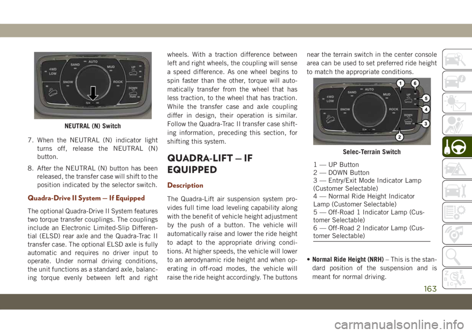
raise the ride height accordingly. The buttonsnear the terrain switch in the center console
area can be used to set preferred ride height
to match the appropriate conditions.
•Normal Ride Height (NRH)– This is the stan-
dard position of the suspension and is
meant for normal driving.
NEUTRAL (N) Switch
Selec-Terrain Switch
1 — UP Button
2 — DOWN Button
3 — Entry/Exit Mode Indicator Lamp
(Customer Selectable)
4 — Normal Ride Height Indicator
Lamp (Customer Selectable)
5 — Off-Road 1 Indicator Lamp (Cus-
tomer Selectable)
6 — Off-Road 2 Indicator Lamp (Cus-
tomer Selectable)
163
Page 168 of 378
Transport Mode
To assist with flat bed towing, the air suspen-
sion system has a feature which will put the
vehicle into Entry/Exit height and disable the
automatic load leveling system. Refer to
“Uconnect Settings” in “Multimedia” for fur-
ther information.
NOTE:
This mode is intended to be enabled with
engine running.
Suspension Display Messages Mode
The “Suspension Display Messages” setting
allows you to only display suspension warn-
ings. Refer to “Uconnect Settings” in “Mul-
timedia” for further information.
NOTE:
This mode is intended to be enabled with
engine running.
Wheel Alignment Mode
Before performing a wheel alignment this
mode must be enabled. Refer to “Uconnect
Settings” in “Multimedia” for further infor-
mation.NOTE:
This mode is intended to be enabled with
engine running.
If equipped with a touch screen radio all
enabling/disabling of air suspension features
must be done through the radio. Refer to
“Uconnect Settings” in “Multimedia” for fur-
ther information.
Instrument Cluster Display Messages
When the appropriate conditions exist, a
message will appear in the instrument clus-
ter. Refer to “Instrument Cluster Display” in
“Getting To Know Your Instrument Panel” for
further information.
Operation
The indicator lamps 3 through 6 will illumi-
nate to show the current position of the
vehicle. Flashing indicator lamps will show a
position which the system is working to
achieve. When raising, if multiple indicator
lamps are flashing on the “UP” button, the
highest flashing indicator lamp is the posi-
tion the system is working to achieve. Whenlowering, if multiple indicators are flashing
on the "DOWN" button the lowest solid indi-
cator lamp is the position the system is work-
ing to achieve.
Pushing the “UP” button once will move the
suspension one position higher from the cur-
rent position, assuming all conditions are
met (i.e. engine running, speed below thresh-
old, etc). The “UP” button can be pushed
multiple times, each push will raise the re-
quested level by one position up to a maxi-
mum position of OR2 or the highest position
allowed based on current conditions (i.e. ve-
hicle speed, etc).
Pushing the “DOWN” button once will move
the suspension one position lower from the
current level, assuming all conditions are met
(i.e. engine running, doors closed, speed be-
low threshold, etc). The “DOWN” button can
be pressed multiple times. Each push will
lower the requested level by one position
down to a minimum of Park Mode or the
lowest position allowed based on current con-
ditions (i.e. vehicle speed, etc.)
STARTING AND OPERATING
166
Page 170 of 378
launches, to minimize wheel slippage. If
equipped with air suspension, the default
ride height for Snow is Normal Ride Height
(NRH).
•Auto– Fully automatic full time four-wheel
drive operation can be used on and off road.
Balances traction with seamless steering
feel to provide improved handling and ac-
celeration over two-wheel drive vehicles. If
equipped with air suspension, the level will
change to Normal Ride Height (NRH).
•Sand– Off road calibration for use on low
traction surfaces such as sand or wet grass.
Driveline is maximized for traction. Some
binding may be felt on less forgiving sur-
faces. The electronic brake controls are set
to limit traction control management of
throttle and wheel spin. If equipped with
air suspension, the default ride height for
Sand is Normal Ride Height (NRH).
•Mud– Off road calibration for use on low
traction surfaces such as mud. Driveline is
maximized for traction. Some binding may
be felt on less forgiving surfaces. The elec-
tronic brake controls are set to limit trac-tion control management of throttle and
wheel spin. If equipped with air suspen-
sion, the level will change to Off Road 1.
•Rock– Off road calibration only available in
4WD Low range. The vehicle is raised (if
equipped with Air Suspension) for im-
proved ground clearance. Traction based
tuning with improved steer-ability for use
on high traction off-road surfaces. Use for
low speed obstacles such as large rocks,
deep ruts, etc. If equipped with air suspen-
sion, the vehicle level will change to Off-
Road 2. If the Selec-Terrain switch is in
ROCK mode, and the transfer case is
switched from 4WD Low to 4WD High, the
Selec-Terrain system will return to AUTO.
NOTE:
Activate the Hill Descent Control or Selec
Speed Control for steep downhill control. See
“Electronic Brake Control System” in this
section for further information.Instrument Cluster Display Messages
When the appropriate conditions exist, a
message will appear in the instrument clus-
ter. Refer to “Instrument Cluster Display” in
“Getting To Know Your Instrument Panel” for
further information.
SELEC-TRACK — IF
EQUIPPED (SRT)
Description
Selec-Track combines the capabilities of the
vehicle control systems, along with driver
input, to provide the best performance for all
terrains.
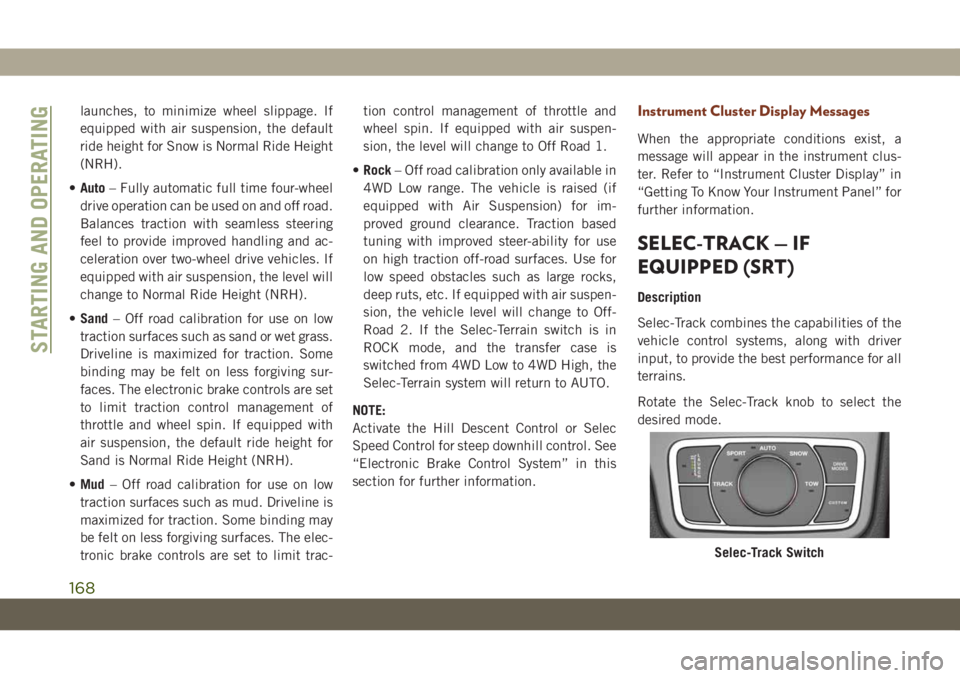
Rotate the Selec-Track knob to select the
desired mode.
Selec-Track Switch
STARTING AND OPERATING
168