reset JEEP GRAND CHEROKEE 2020 Owner handbook (in English)
[x] Cancel search | Manufacturer: JEEP, Model Year: 2020, Model line: GRAND CHEROKEE, Model: JEEP GRAND CHEROKEE 2020Pages: 378, PDF Size: 6.88 MB
Page 27 of 378
NOTE:
• When the child lock system is engaged, the
door can be opened only by using the out-
side door handle even though the inside
door lock is in the unlocked position.
• After disengaging the Child-Protection Door
Lock system, always test the door from the
inside to make certain it is in the desired
position.
• After engaging the Child-Protection Door
Lock system, always test the door from the
inside to make certain it is in the desired
position.
• For emergency exit with the system en-
gaged, pull up on the door lock knob (un-
locked position), roll down the window, and
open the door with the outside door handle.
WARNING!
Avoid trapping anyone in a vehicle in a
collision. Remember that the rear doors
can only be opened from the outside when
the Child-Protection locks are engaged
(locked).NOTE:
Always use this device when carrying chil-
dren. After engaging the child lock on both
rear doors, check for effective engagement by
trying to open a door with the internal handle.
Once the Child-Protection Door Lock system
is engaged, it is impossible to open the doors
from inside the vehicle. Before getting out of
the car, be sure to check that there is no one
left inside.
SEATS
Seats are a part of the Occupant Restraint
System of the vehicle.
WARNING!
• It is dangerous to ride in a cargo area,
inside or outside of a vehicle. In a colli-
sion, people riding in these areas are
more likely to be seriously injured or
killed.
• Do not allow people to ride in any area of
your vehicle that is not equipped with
seats and seat belts. In a collision,
WARNING!
people riding in these areas are more
likely to be seriously injured or killed.
• Be sure everyone in your vehicle is in a
seat and using a seat belt properly.
Driver Memory Seat — If Equipped
This feature allows the driver to store up to
two different memory profiles for easy recall
through a memory switch. Each memory pro-
file contains desired position settings for the
driver seat, side mirrors, and power tilt and
telescopic steering column (if equipped) and
a set of desired radio station presets. Your key
fob can also be programmed to recall the
same positions when the unlock button is
pushed.
NOTE:
Your vehicle is equipped with two key fobs,
one key fob can be linked to memory position
1 and the other key fob can be linked to
memory position 2.
25
Page 28 of 378
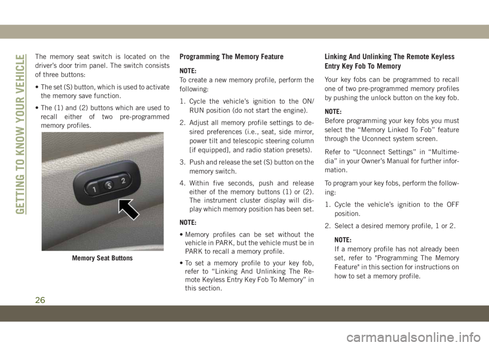
The memory seat switch is located on the
driver’s door trim panel. The switch consists
of three buttons:
• The set (S) button, which is used to activate
the memory save function.
• The (1) and (2) buttons which are used to
recall either of two pre-programmed
memory profiles.Programming The Memory Feature
NOTE:
To create a new memory profile, perform the
following:
1. Cycle the vehicle’s ignition to the ON/
RUN position (do not start the engine).
2. Adjust all memory profile settings to de-
sired preferences (i.e., seat, side mirror,
power tilt and telescopic steering column
[if equipped], and radio station presets).
3. Push and release the set (S) button on the
memory switch.
4. Within five seconds, push and release
either of the memory buttons (1) or (2).
The instrument cluster display will dis-
play which memory position has been set.
NOTE:
• Memory profiles can be set without the
vehicle in PARK, but the vehicle must be in
PARK to recall a memory profile.
• To set a memory profile to your key fob,
refer to “Linking And Unlinking The Re-
mote Keyless Entry Key Fob To Memory” in
this section.
Linking And Unlinking The Remote Keyless
Entry Key Fob To Memory
Your key fobs can be programmed to recall
one of two pre-programmed memory profiles
by pushing the unlock button on the key fob.
NOTE:
Before programming your key fobs you must
select the “Memory Linked To Fob” feature
through the Uconnect system screen.
Refer to “Uconnect Settings” in “Multime-
dia” in your Owner’s Manual for further infor-
mation.
To program your key fobs, perform the follow-
ing:
1. Cycle the vehicle’s ignition to the OFF
position.
2. Select a desired memory profile, 1 or 2.
NOTE:
If a memory profile has not already been
set, refer to "Programming The Memory
Feature" in this section for instructions on
how to set a memory profile.
Memory Seat Buttons
GETTING TO KNOW YOUR VEHICLE
26
Page 33 of 378
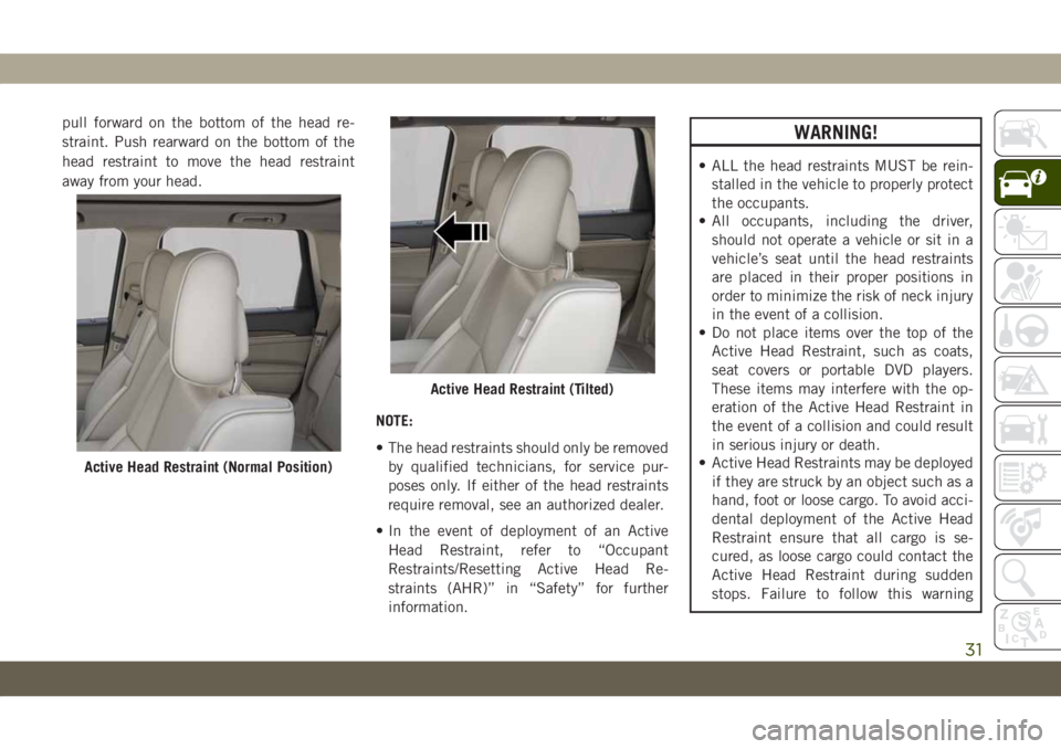
pull forward on the bottom of the head re-
straint. Push rearward on the bottom of the
head restraint to move the head restraint
away from your head.
NOTE:
• The head restraints should only be removed
by qualified technicians, for service pur-
poses only. If either of the head restraints
require removal, see an authorized dealer.
• In the event of deployment of an Active
Head Restraint, refer to “Occupant
Restraints/Resetting Active Head Re-
straints (AHR)” in “Safety” for further
information.WARNING!
• ALL the head restraints MUST be rein-
stalled in the vehicle to properly protect
the occupants.
• All occupants, including the driver,
should not operate a vehicle or sit in a
vehicle’s seat until the head restraints
are placed in their proper positions in
order to minimize the risk of neck injury
in the event of a collision.
• Do not place items over the top of the
Active Head Restraint, such as coats,
seat covers or portable DVD players.
These items may interfere with the op-
eration of the Active Head Restraint in
the event of a collision and could result
in serious injury or death.
• Active Head Restraints may be deployed
if they are struck by an object such as a
hand, foot or loose cargo. To avoid acci-
dental deployment of the Active Head
Restraint ensure that all cargo is se-
cured, as loose cargo could contact the
Active Head Restraint during sudden
stops. Failure to follow this warning
Active Head Restraint (Normal Position)
Active Head Restraint (Tilted)
31
Page 38 of 378
• If the exterior mirrors were manually
folded, they will not automatically unfold.
NOTE:
The Automatic Fold/Unfold Mirrors feature is
not turned on when delivered from the fac-
tory. The Automatic Fold/Unfold Mirrors fea-
ture can be turned on and off using the
Uconnect System. Refer to “Uconnect Set-
tings” in “Multimedia” in your Owner’s
Manual for further information.
Resetting The Power Folding Outside Mirrors
You may need to reset the power folding
mirrors if the following occurs:
• The mirrors are accidentally blocked while
folding.
• The mirrors are accidentally manually
folded/unfolded.
• The mirrors come out of the unfolded posi-
tion.
• The mirrors shake and vibrate at normal
driving speeds.To reset the power folding mirrors: Fold and
unfold them by pushing the button (this may
require multiple button pushes). This resets
them to their normal position.
Tilt Side Mirrors In Reverse (Available
With Memory Seat Only) — If Equipped
Tilt Side Mirrors In Reverse provides auto-
matic outside mirror positioning which will
aid the driver’s view of the ground rearward of
the front doors. Outside mirrors will move
slightly downward from the present position
when the vehicle is shifted into REVERSE.
Outside mirrors will then return to the original
position when the vehicle is shifted out of
REVERSE position. Each stored memory seat
setting will have an associated Tilt Side Mir-
rors In Reverse position.
NOTE:
The Tilt Side Mirrors In Reverse feature is not
turned on when delivered from the factory.
The Tilt Side Mirrors In Reverse feature can
be turned on and off using the Uconnect
System. Refer to “Uconnect Settings” in
“Multimedia” in the Owner’s Manual for fur-
ther information.
EXTERIOR LIGHTS
Headlight Switch
The headlight switch is located on the right
side of the instrument panel, next to the
steering wheel. The headlight switch controls
the operation of the headlights, parking
lights, instrument panel lights, cargo lights,
and fog lights (if equipped).
GETTING TO KNOW YOUR VEHICLE
36
Page 57 of 378
will close fully and stop automatically. This is
called “Express Close”. During Express Close
operation, any other actuation of the switch
will stop the sunroof.
Manual
To close the sunroof, push and hold the
switch in the forward position. Any release of
the switch will stop the movement and the
sunroof will remain in a partially closed con-
dition until the sunroof switch is pushed
again.
Sunshade Operation
The sunshade can be opened manually. How-
ever, the sunshade will open automatically as
the sunroof opens.
NOTE:
The sunshade cannot be closed if the sunroof
is open.
Pinch Protect Feature
This feature will detect an obstruction in the
closing of the sunroof during the Express
Close operation. If an obstruction in the path
of the sunroof is detected, the sunroof will
automatically retract. Remove the obstruc-
tion if this occurs.
NOTE:
If three consecutive sunroof close attempts
result in Pinch Protect reversals, Pinch Pro-
tect will disable and the sunroof must be
closed in Manual Mode.
Venting Sunroof — Express
Push and release the Vent button within one
half second and the sunroof will open to the
vent position. This is called “Express Vent”
and it will occur regardless of sunroof posi-
tion. During Express Vent operation, any
movement of the switch will stop the sunroof.
Sunroof Maintenance
Use only a non-abrasive cleaner and a soft
cloth to clean the glass panel.
Relearn Procedure
For vehicles equipped with a single-pane
sunroof, there is a relearn procedure that
allows you to reset the sunroof when the
“Express Open” feature stops working. To
reset the sunroof, follow these steps:
1. Set the ignition to the ACC or ON/RUN
position.
2. Make sure that the sunroof is fully closed.
3. Push sunroof switch forward and hold.
The sunroof will close fully then move to
the Vent position after 10 seconds.
4. Release the sunroof switch, then push
forward and hold the switch again within
5 seconds to begin the relearn process.
The sunroof will complete one full cycle
and return to the Fully Closed position.
NOTE:
If the sunroof switch is released anytime
during the relearn cycle, the procedure
will need to be repeated starting from the
first step.
55
Page 58 of 378
5. Once the sunroof has stopped in the Fully
Closed position, release the sunroof
switch. The sunroof is now reset and ready
to use.
COMMANDVIEW SUNROOF
WITH POWER SHADE — IF
EQUIPPED
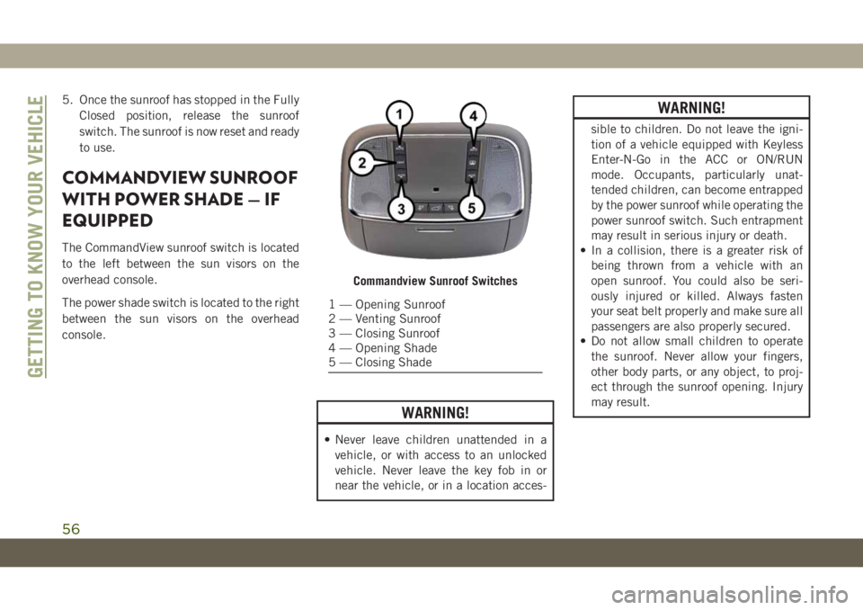
The CommandView sunroof switch is located
to the left between the sun visors on the
overhead console.
The power shade switch is located to the right
between the sun visors on the overhead
console.
WARNING!
• Never leave children unattended in a
vehicle, or with access to an unlocked
vehicle. Never leave the key fob in or
near the vehicle, or in a location acces-
WARNING!
sible to children. Do not leave the igni-
tion of a vehicle equipped with Keyless
Enter-N-Go in the ACC or ON/RUN
mode. Occupants, particularly unat-
tended children, can become entrapped
by the power sunroof while operating the
power sunroof switch. Such entrapment
may result in serious injury or death.
• In a collision, there is a greater risk of
being thrown from a vehicle with an
open sunroof. You could also be seri-
ously injured or killed. Always fasten
your seat belt properly and make sure all
passengers are also properly secured.
• Do not allow small children to operate
the sunroof. Never allow your fingers,
other body parts, or any object, to proj-
ect through the sunroof opening. Injury
may result.
Commandview Sunroof Switches
1 — Opening Sunroof
2 — Venting Sunroof
3 — Closing Sunroof
4 — Opening Shade
5 — Closing Shade
GETTING TO KNOW YOUR VEHICLE
56
Page 63 of 378
NOTE:
The liftgate unlock feature is built into the
electronic liftgate release.
Power Liftgate — If Equipped
The power liftgate may be
opened by pushing the electronic
liftgate release (refer to “Keyless
Enter-N-Go — Passive Entry” located in
“Getting To Know Your Vehicle” in your Own-
er’s Manual for further information), or bypushing the liftgate button on the key fob.
Push the liftgate button on the key fob twice
within five seconds to open the power lift-
gate. Once the liftgate is open, pushing the
button twice within five seconds a second
time will close the liftgate.
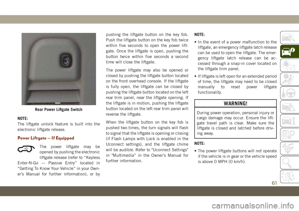
The power liftgate may also be opened or
closed by pushing the liftgate button located
on the front overhead console. If the liftgate
is fully open, the liftgate can be closed by
pushing the liftgate button located on the left
rear trim panel, near the liftgate opening. If
the liftgate is in motion, pushing the liftgate
button located on the left rear trim panel will
reverse the liftgate.
When the liftgate button on the key fob is
pushed two times, the turn signals will flash
to signal that the liftgate is opening or closing
(if Flash Lamps with Lock is enabled in the
Uconnect settings), and the liftgate chime
will be audible. Refer to "Uconnect Settings"
in "Multimedia” in the Owner’s Manual for
further information.NOTE:
• In the event of a power malfunction to the
liftgate, an emergency liftgate latch release
can be used to open the liftgate. The emer-
gency liftgate latch release can be ac-
cessed through a snap-in cover located on
the liftgate trim panel.
• If liftgate is left open for an extended period
of time, the liftgate may need to be closed
manually to reset power liftgate
functionality.
WARNING!
During power operation, personal injury or
cargo damage may occur. Ensure the lift-
gate travel path is clear. Make sure the
liftgate is closed and latched before driv-
ing away.
NOTE:
• The power liftgate buttons will not operate
if the vehicle is in gear or the vehicle speed
is above 0 MPH (0 km/h).Rear Power Liftgate Switch
2
61
Page 69 of 378
• Push thedownarrow button to scroll down-
ward through the main menu and sub-
menus (Speedometer, MPH/km/h, Vehicle
Info, Terrain, Driver Assist, Fuel Economy,
Trip A, Trip B, Stop/Start, Audio, Naviga-
tion, Stored Messages, Screen Setup and
Speed Warning).
• Push therightarrow button to access the
information screens or submenu screens of
a main menu item.
• Push theleftarrow button to access the
information screens or submenu screens of
a main menu item.
• Push theOKbutton to access/select the
information screens or submenu screens of
a main menu item. Push and hold theOK
button for two seconds to reset displayed/
selected features that can be reset.
Oil Change Indicator System — If
Equipped
Your vehicle is equipped with an engine oil
change indicator system. The “Oil Change
Due” message will display in the instrument
cluster display for five seconds after a single
chime has sounded, to indicate the nextscheduled oil change interval. The engine oil
change indicator system is duty cycle based,
which means the engine oil change interval
may fluctuate, dependent upon your personal
driving style.
To have the oil changed, please refer to an
authorized dealer.
Instrument Cluster Display Selectable
Items
The instrument cluster display can be used to
view the main menu items for several fea-
tures. Use theupanddownarrow buttons to
scroll through the driver interactive display
menu options until the desired menu is
reached.
NOTE:
Depending on the vehicle’s options, feature
settings may vary.
Speedometer Trip
Accessibility — If
EquippedAudio
Vehicle Info Stored Messages
Driver Assist Screen Setup
Stop/Start — If
EquippedTerrain — If
Equipped
Performance Fea-
tures — If EquippedDiagnostics — If
Equipped
Fuel Economy Speed Warning
Refer to “Instrument Cluster Display” in
“Getting To Know Your Instrument Panel” in
the Owner’s Manual for further information.
Display Menu items
SRT Instrument Cluster Display Performance
Features
The instrument cluster display can be used to
program the following Performance Features.
67
Page 72 of 378
CAUTION!
See an authorized dealer, as damage to the
exhaust system could occur soon with con-
tinued operation.
•Exhaust Filter Full — Power Reduced See
Dealer— This message indicates the PCM
has derated the engine to limit the likeli-
hood of permanent damage to the after-
treatment system. If this condition is not
corrected and a dealer service is not per-
formed, extensive exhaust after-treatment
damage can occur. To correct this condition
it will be necessary to have your vehicle
serviced by an authorized dealer.
NOTE:
Failing to follow the oil change indicator,
changing your oil and resetting the oil change
indicator by 0 miles remaining will prevent
the diesel exhaust filter from performing it's
cleaning routine. This will shortly result in a
Malfunction Indicator Light (MIL) and re-
duced engine power. Only an authorized
dealer will be able to correct this condition.
CAUTION!
See an authorized dealer, as damage to the
exhaust system could occur soon with con-
tinued operation.
Fuel System Messages — If Equipped
The following chart contains a list of different
messages that may appear in the instrument
cluster, depending on different system or fuel
conditions. Use the descriptions to interpret
what the message means and determine the
best action to take.
GETTING TO KNOW YOUR INSTRUMENT PANEL
70
Page 104 of 378
FCW Braking Status And Sensitivity
The FCW Sensitivity and Active Braking sta-
tus are programmable through the Uconnect
System. Refer to “Uconnect Settings” in
“Multimedia” in the Owner’s Manual for fur-
ther information.
The default sensitivity of FCW is the “Me-
dium” setting and the system status is
“Warning & Braking”. This allows the system
to warn the driver of a possible collision with
the vehicle in front using audible/visual warn-
ings and it applies autonomous braking.
Changing the FCW status to “Far” setting
allows the system to warn the driver of a
possible collision with the vehicle in front
using audible/visual warning when the latter
is at a farther distance than "Medium" set-
ting. This provides the most reaction time to
avoid a possible collision.
Changing the FCW status to the “Near” set-
ting, allows the system to warn the driver of a
possible collision with the vehicle in front
when the distance between the vehicle in the
front is much closer. This setting providesless reaction time than the “Far” and “Me-
dium” settings, which allows for a more dy-
namic driving experience.
NOTE:
• Changing the FCW status to “Only Warn-
ing” prevents the system from providing
limited active braking, or additional brake
support if the driver is not braking ad-
equately in the event of a potential frontal
collision, but maintains the audible and
visual warnings.
• Changing the FCW status to “Off” prevents
the system from providing autonomous
braking, or additional brake support if the
driver is not braking adequately in the event
of a potential frontal collision.
• The system will NOT retain the last setting
selected by the driver after ignition shut
down. The system will reset to "Medium"
sensitivity and system status as “Warning &
Braking” when the vehicle is restarted.• FCW may not react to irrelevant objects
such as overhead objects, ground reflec-
tions, objects not in the path of the vehicle,
stationary objects that are far away, oncom-
ing traffic, or leading vehicles with the
same or higher rate of speed.
• FCW will be disabled like ACC, with the
unavailable screens.
FCW Limited Warning
If the instrument cluster displays “ACC/FCW
Limited Functionality” or “ACC/FCW Limited
Functionality Clean Front Windshield” mo-
mentarily, there may be a condition that lim-
its FCW functionality. Although the vehicle is
still drivable under normal conditions, the
active braking may not be fully available.
Once the condition that limited the system
performance is no longer present, the system
will return to its full performance state. If the
problem persists, see your authorized dealer.
SAFETY
102