reset JEEP GRAND CHEROKEE 2020 Owner handbook (in English)
[x] Cancel search | Manufacturer: JEEP, Model Year: 2020, Model line: GRAND CHEROKEE, Model: JEEP GRAND CHEROKEE 2020Pages: 378, PDF Size: 6.88 MB
Page 118 of 378
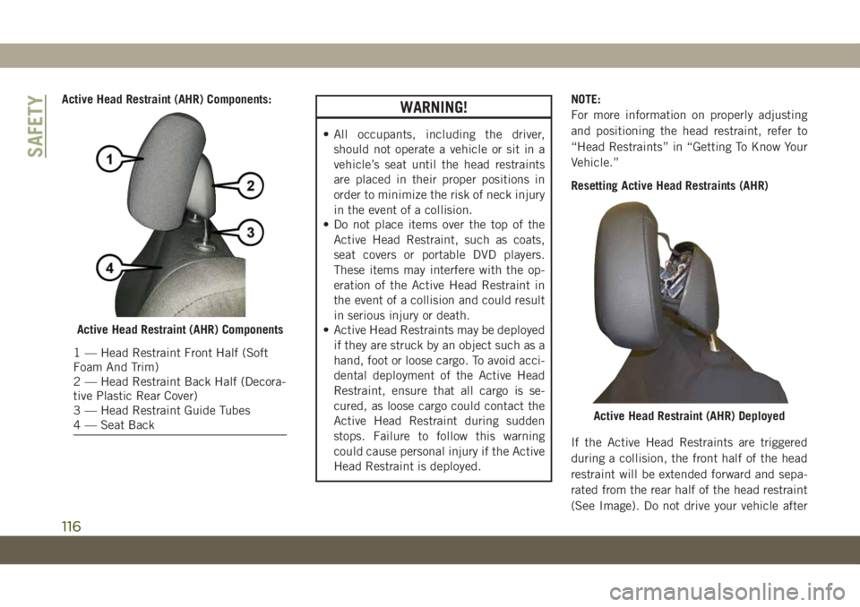
Active Head Restraint (AHR) Components:WARNING!
• All occupants, including the driver,
should not operate a vehicle or sit in a
vehicle’s seat until the head restraints
are placed in their proper positions in
order to minimize the risk of neck injury
in the event of a collision.
• Do not place items over the top of the
Active Head Restraint, such as coats,
seat covers or portable DVD players.
These items may interfere with the op-
eration of the Active Head Restraint in
the event of a collision and could result
in serious injury or death.
• Active Head Restraints may be deployed
if they are struck by an object such as a
hand, foot or loose cargo. To avoid acci-
dental deployment of the Active Head
Restraint, ensure that all cargo is se-
cured, as loose cargo could contact the
Active Head Restraint during sudden
stops. Failure to follow this warning
could cause personal injury if the Active
Head Restraint is deployed.NOTE:
For more information on properly adjusting
and positioning the head restraint, refer to
“Head Restraints” in “Getting To Know Your
Vehicle.”
Resetting Active Head Restraints (AHR)
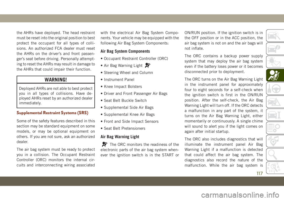
If the Active Head Restraints are triggered
during a collision, the front half of the head
restraint will be extended forward and sepa-
rated from the rear half of the head restraint
(See Image). Do not drive your vehicle after
Active Head Restraint (AHR) Components
1 — Head Restraint Front Half (Soft
Foam And Trim)
2 — Head Restraint Back Half (Decora-
tive Plastic Rear Cover)
3 — Head Restraint Guide Tubes
4 — Seat Back
Active Head Restraint (AHR) Deployed
SAFETY
116
Page 119 of 378
the AHRs have deployed. The head restraint
must be reset into the original position to best
protect the occupant for all types of colli-
sions. An authorized FCA dealer must reset
the AHRs on the driver’s and front passen-
ger’s seat before driving. Personally attempt-
ing to reset the AHRs may result in damage to
the AHRs that could impair their function.
WARNING!
Deployed AHRs are not able to best protect
you in all types of collisions. Have de-
ployed AHRs reset by an authorized dealer
immediately.
Supplemental Restraint Systems (SRS)
Some of the safety features described in this
section may be standard equipment on some
models, or may be optional equipment on
others. If you are not sure, ask an authorized
dealer.
The air bag system must be ready to protect
you in a collision. The Occupant Restraint
Controller (ORC) monitors the internal cir-
cuits and interconnecting wiring associatedwith the electrical Air Bag System Compo-
nents. Your vehicle may be equipped with the
following Air Bag System Components:
Air Bag System Components
• Occupant Restraint Controller (ORC)
• Air Bag Warning Light
• Steering Wheel and Column
• Instrument Panel
• Knee Impact Bolsters
• Driver and Front Passenger Air Bags
• Seat Belt Buckle Switch
• Supplemental Side Air Bags
• Supplemental Knee Air Bags
• Front and Side Impact Sensors
• Seat Belt Pretensioners
Air Bag Warning Light
The ORC monitors the readiness of the
electronic parts of the air bag system when-
ever the ignition switch is in the START orON/RUN position. If the ignition switch is in
the OFF position or in the ACC position, the
air bag system is not on and the air bags will
not inflate.
The ORC contains a backup power supply
system that may deploy the air bag system
even if the battery loses power or it becomes
disconnected prior to deployment.
The ORC turns on the Air Bag Warning Light
in the instrument panel for approximately
four to eight seconds for a self-check when
the ignition switch is first in the ON/RUN
position. After the self-check, the Air Bag
Warning Light will turn off. If the ORC detects
a malfunction in any part of the system, it
turns on the Air Bag Warning Light, either
momentarily or continuously. A single chime
will sound to alert you if the light comes on
again after initial startup.
The ORC also includes diagnostics that will
illuminate the instrument panel Air Bag
Warning Light if a malfunction is detected
that could affect the air bag system. The
diagnostics also record the nature of the
malfunction. While the air bag system is
117
Page 127 of 378
Enhanced Accident Response System
In the event of an impact, if the communica-
tion network remains intact, and the power
remains intact, depending on the nature of
the event, the ORC will determine whether to
have the Enhanced Accident Response Sys-
tem perform the following functions:
• Cut off fuel to the engine (If Equipped)
• Cut off battery power to the electric motor
(If Equipped)
• Flash hazard lights as long as the battery
has power
• Turn on the interior lights, which remain on
as long as the battery has power or for 15
minutes from the intervention of the En-
hanced Accident Response System.
• Unlock the power door locks.
Your vehicle may also be designed to perform
any of these other functions in response to
the Enhanced Accident Response System:
• Turn off the Fuel Filter Heater, Turn off the
HVAC Blower Motor, Close the HVAC Circu-
lation Door• Cut off battery power to the:
– Engine
– Electric Motor (if equipped)
– Electric power steering
– Brake booster
– Electric park brake
– Automatic transmission gear selector
– Horn
– Front wiper
– Headlamp washer pump
NOTE:
After an accident, remember to cycle the
ignition to the STOP (OFF/LOCK) position
and remove the key from the ignition switch
to avoid draining the battery. Carefully check
the vehicle for fuel leaks in the engine com-
partment and on the ground near the engine
compartment and fuel tank before resetting
the system and starting the engine. If there
are no fuel leaks or damage to the vehicle
electrical devices (e.g. headlights) after an
accident, reset the system by following the
procedure described below. If you have any
doubt, contact an authorized dealer.
Enhanced Accident Response System Reset
Procedure
In order to reset the Enhanced Accident Re-
sponse System functions after an event, the
ignition switch must be changed from igni-
tion START or ON/RUN to ignition OFF. Care-
fully check the vehicle for fuel leaks in the
engine compartment and on the ground near
the engine compartment and fuel tank before
resetting the system and starting the engine.
Maintaining Your Air Bag System
WARNING!
• Modifications to any part of the air bag
system could cause it to fail when you
need it. You could be injured if the air
bag system is not there to protect you.
Do not modify the components or wiring,
including adding any kind of badges or
stickers to the steering wheel hub trim
cover or the upper passenger side of the
instrument panel. Do not modify the
front bumper, vehicle body structure, or
add aftermarket side steps or running
boards.
125
Page 154 of 378
• STOP/START OFF switch is pushed.
• A STOP/START system error occurs.
• 4WD system is put into 4LO mode.
To Manually Turn Off The Stop/Start
System
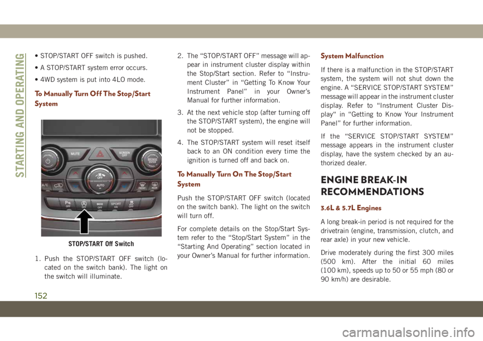
1. Push the STOP/START OFF switch (lo-
cated on the switch bank). The light on
the switch will illuminate.2. The “STOP/START OFF” message will ap-
pear in instrument cluster display within
the Stop/Start section. Refer to “Instru-
ment Cluster” in “Getting To Know Your
Instrument Panel” in your Owner’s
Manual for further information.
3. At the next vehicle stop (after turning off
the STOP/START system), the engine will
not be stopped.
4. The STOP/START system will reset itself
back to an ON condition every time the
ignition is turned off and back on.
To Manually Turn On The Stop/Start
System
Push the STOP/START OFF switch (located
on the switch bank). The light on the switch
will turn off.
For complete details on the Stop/Start Sys-
tem refer to the “Stop/Start System” in the
“Starting And Operating” section located in
your Owner’s Manual for further information.
System Malfunction
If there is a malfunction in the STOP/START
system, the system will not shut down the
engine. A “SERVICE STOP/START SYSTEM”
message will appear in the instrument cluster
display. Refer to “Instrument Cluster Dis-
play“ in “Getting to Know Your Instrument
Panel” for further information.
If the “SERVICE STOP/START SYSTEM”
message appears in the instrument cluster
display, have the system checked by an au-
thorized dealer.
ENGINE BREAK-IN
RECOMMENDATIONS
3.6L & 5.7L Engines
A long break-in period is not required for the
drivetrain (engine, transmission, clutch, and
rear axle) in your new vehicle.
Drive moderately during the first 300 miles
(500 km). After the initial 60 miles
(100 km), speeds up to 50 or 55 mph (80 or
90 km/h) are desirable.
STOP/START Off Switch
STARTING AND OPERATING
152
Page 171 of 378
Refer to “SRT Drive Modes” in the “Multime-
dia” section in your Owner’s Manual for fur-
ther information.
Selec-Track consists of the following posi-
tions:
•Sport– Dry weather, on-road calibration.
Performance based tuning that provides a
rear wheel drive feel but with improved
handling and acceleration over a two-wheel
drive vehicle. This feature will reset to
AUTO on an ignition cycle.
•Snow– Tuning set for additional stability in
inclement weather. Use on and off road on
loose traction surfaces such as snow. This
feature will reset to AUTO upon an ignition
cycle.
•Auto– Fully automatic full time four-wheel
drive operation can be used on and off road.
Balances traction with seamless steering
feel to provide improved handling and ac-
celeration over two-wheel drive vehicles.•Track– Track road calibration for use on
high traction surfaces. Driveline is maxi-
mized for traction. Some binding may be
felt on less forgiving surfaces. This feature
will reset to AUTO on an ignition cycle.
•To w– Use this mode for towing and hauling
heavy loads. Vehicle suspension will go to
sport mode. Trailer sway control is enabled
in the ESC system. This feature will reset to
AUTO upon an ignition cycle.
Custom
This mode allows the driver to create a cus-
tom vehicle configuration that is saved for
quick selection of favorite settings. The sys-
tem will return to AUTO mode when the
ignition switch is cycled from RUN to OFF to
RUN, if this mode is selected. While in Cus-
tom Mode the Stability, Transmission, Steer-
ing, Suspension, all-wheel drive set up, and
Paddle shifter settings may be configured
through the custom mode set-up.
NOTE:
Refer to “SRT Drive Modes” in the “Multime-
dia” section in your Owner’s Manual for fur-
ther information.
Active Damping System
This vehicle is equipped with an electronic
controlled damping system. This system re-
duces body roll and pitch in many driving
situations including cornering, acceleration
and braking. There are 3 modes:
•Street Mode(Available in terrain positions
AUTO, SNOW and CUSTOM.) — Used dur-
ing highway speeds where a touring sus-
pension feel is desired.
•Sport Mode(Available in terrain positions
AUTO, SPORT, CUSTOM and TOW.) — Pro-
vides a firm suspension for better handling.
•Track Mode(Available in terrain positions
AUTO, TRACK and CUSTOM.) — Provides
a full firm suspension for an aggressive
track experience.
Refer to “SRT Drive Modes” in the “Multime-
dia” section in your Owner’s Manual for fur-
ther information.
169
Page 175 of 378
NOTE:
In order to ensure proper operation, the
Speed Control System has been designed toshut down if multiple Speed Control func-
tions are operated at the same time. If this
occurs, the Speed Control System can be
reactivated by pushing the Speed Control
on/off button and resetting the desired ve-
hicle set speed.
WARNING!
Speed Control can be dangerous where the
system cannot maintain a constant speed.
Your vehicle could go too fast for the con-
ditions, and you could lose control and
have an accident. Do not use Speed Con-
trol in heavy traffic or on roads that are
winding, icy, snow-covered or slippery.
To Activate
Push the on/off button to activate the Speed
Control. “CRUISE CONTROL READY” will
appear in the instrument cluster display to
indicate the Speed Control is on. To turn the
system off, push the on/off button a second
time. “CRUISE CONTROL OFF” will appear
in the instrument cluster display to indicate
the Speed Control is off. The system should
be turned off when not in use.
WARNING!
Leaving the Speed Control system on when
not in use is dangerous. You could acci-
dentally set the system or cause it to go
faster than you want. You could lose con-
trol and have an accident. Always leave the
system OFF when you are not using it.
To Set A Desired Speed
Turn the Speed Control on. When the vehicle
has reached the desired speed, push the SET
(+) or SET (-) button and release. Release the
accelerator and the vehicle will operate at the
selected speed. Once a speed has been set, a
message “CRUISE CONTROL SET TO MPH
(km/h)” will appear indicating what speed
was set. A cruise indicator lamp, along with
set speed will also appear and stay on in the
instrument cluster when the speed is set.
To Resume Speed
To resume a previously set speed, push the
RES button and release. Resume can be used
at any speed above 20 mph (32 km/h).
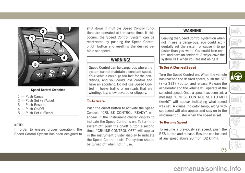
Speed Control Switches
1 — Push Cancel
2 — Push Set (+)/Accel
3 — Push Resume
4 — Push On/Off
5 — Push Set (-)/Decel
173
Page 176 of 378
To Deactivate
A soft tap on the brake pedal, pushing the
CANC button, or normal brake pressure while
slowing the vehicle will deactivate the Speed
Control without erasing the set speed from
memory.
Pushing the on/off button or turning the igni-
tion switch OFF erases the set speed from
memory.
ADAPTIVE CRUISE
CONTROL (ACC) — IF
EQUIPPEDIf your vehicle is equipped with Adaptive
Cruise Control, the controls operate exactly
the same as Speed Control with only a couple
of differences. With this option, you can set a
specified distance you would like to maintain
between you and the vehicle in front of you.
If the ACC sensor detects a vehicle ahead,
ACC will apply limited braking or acceleration
automatically to maintain a preset following
distance, while matching the speed of the
vehicle ahead.
If the sensor does not detect a vehicle ahead
of you, ACC will maintain a fixed set speed.
To Activate/Deactivate
Push and release the Adaptive Cruise Control
(ACC) on/off button. The ACC menu in the
instrument cluster displays “ACC Ready.”
To turn the system off, push and release the
Adaptive Cruise Control (ACC) on/off button
again. At this time, the system will turn off
and the instrument cluster displays “Adap-
tive Cruise Control (ACC) Off.”
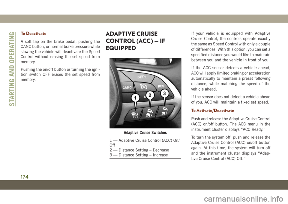
Adaptive Cruise Switches
1 — Adaptive Cruise Control (ACC) On/
Off
2 — Distance Setting – Decrease
3 — Distance Setting – Increase
STARTING AND OPERATING
174
Page 201 of 378
Recreational Towing — Two Wheel Drive
Models
DO NOT flat tow this vehicle. Damage to the
drivetrain will result.
Recreational towing (for two-wheel drive
models) is allowed ONLY if the rear wheels
are OFF the ground. This may be accom-
plished using a tow dolly or vehicle trailer. If
using a tow dolly, follow this procedure:
1. Properly secure the dolly to the tow ve-
hicle, following the dolly manufacturer's
instructions.
NOTE:
If vehicle is equipped with Quadra-Lift air
suspension, ensure the vehicle is set to
Normal Ride Height.
2. Drive the rear wheels onto the tow dolly.
3. Firmly apply the parking brake. Shift the
transmission into PARK.
4. Turn the ignition OFF.
5. Properly secure the rear wheels to the
dolly, following the dolly manufacturer’s
instructions.6. Turn the ignition to the ON/RUN mode,
but do not start the engine.
7. Confirm that the steering column is
unlocked.
8. Install a suitable clamping device, de-
signed for towing, to secure the front
wheels in the straight position.
9. Disconnect the negative battery cable,
and secure it away from the battery post.
NOTE:
Disconnecting your vehicle battery will
erase radio presets and may affect other
vehicle settings. It may also trigger vari-
ous fault codes, causing MIL illumination
when the battery is reconnected.
CAUTION!
Towing with the rear wheels on the ground
will cause severe transmission damage.
Damage from improper towing is not cov-
ered under the New Vehicle Limited
Warranty.
Recreational Towing — Quadra-Trac I
(Single-Speed Transfer Case) Four-Wheel
Drive Models
Recreational towing is not allowed.These
models do not have a NEUTRAL (N) position
in the transfer case.
NOTE:
This vehicle may be towed on a flatbed or
vehicle trailer provided all four wheels areOFF
the ground.
CAUTION!
Towing this vehicle in violation of the
above requirements can cause severe
transmission and/or transfer case damage.
Damage from improper towing is not cov-
ered under the New Vehicle Limited
Warranty.
199
Page 203 of 378
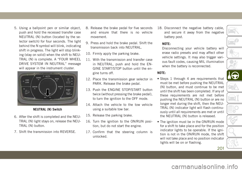
5. Using a ballpoint pen or similar object,
push and hold the recessed transfer case
NEUTRAL (N) button (located by the se-
lector switch) for four seconds. The light
behind the N symbol will blink, indicating
shift in progress. The light will stop blink-
ing (stay on solid) when the shift to NEU-
TRAL (N) is complete. A “FOUR WHEEL
DRIVE SYSTEM IN NEUTRAL” message
will appear in the instrument cluster.
6. After the shift is completed and the NEU-
TRAL (N) light stays on, release the NEU-
TRAL (N) button.
7. Shift the transmission into REVERSE.8. Release the brake pedal for five seconds
and ensure that there is no vehicle
movement.
9. Press and hold the brake pedal. Shift the
transmission back into NEUTRAL.
10. Firmly apply the parking brake.
11. With the transmission and transfer case
in NEUTRAL, push and hold the EN-
GINE START/STOP button until the en-
gine turns off.
12. Place the transmission gear selector in
PARK. Release the brake pedal.
13. Push the ENGINE STOP/START button
twice (without pressing the brake pedal),
to turn the ignition to the OFF mode.
14. Attach the vehicle to the tow vehicle
using a suitable tow bar.
15. Release the parking brake.
16. Turn the ignition to the ON/RUN posi-
tion, but do not start the engine.
17. Confirm that the steering column is
unlocked.18. Disconnect the negative battery cable,
and secure it away from the negative
battery post.
NOTE:
Disconnecting your vehicle battery will
erase radio presets and may affect other
vehicle settings. It may also trigger vari-
ous fault codes, causing MIL illumination
when the battery is reconnected.
NOTE:
• Steps 1 through 4 are requirements that
must be met before pushing the NEUTRAL
(N) button, and must continue to be met
until the shift has been completed. If any of
these requirements are not met before
pushing the NEUTRAL (N) button or are no
longer met during the shift, then the NEU-
TRAL (N) indicator light will flash continu-
ously until all requirements are met or until
the NEUTRAL (N) button is released.
• The ignition must be in the ON/RUN mode
for a shift to take place and for the position
indicator lights to be operable. If the igni-
tion is not in the ON/RUN mode, the shift
will not take place and no position indicator
lights will be on or flashing.
NEUTRAL (N) Switch
201
Page 238 of 378
SCHEDULED SERVICING
Scheduled Servicing — Non SRT
Correct servicing is crucial for guaranteeing a
long life for the car under the best conditions.
For this reason, Jeep has planned a series of
checks and services at fixed distance inter-
vals and, where provided, at fixed time inter-
vals, as described in the Scheduled Servicing
plan. To keep the car’s efficiency in tip-top
condition, in the following Scheduled Service
plan pages a few additional checks are listed
that should be carried out more frequently
with respect to the normal coupon redemp-
tion schedule. Scheduled Servicing is offered
by all authorized dealerships according to
fixed time or mileage intervals. If, during
each operation, in addition to the ones
scheduled, the need arises for further re-
placements or repairs, these may be carried
out with the owner's explicit agreement only.
The technicians at your dealership know your
vehicle best, and have access to factory
trained information, genuine Mopar parts,
and specially designed electronic and me-
chanical tools that can help prevent futurecostly repairs. If your car is used frequently
for towing, the interval between one sched-
uled servicing operation and the next should
be reduced. More frequent maintenance may
be needed for vehicles in severe operating
conditions, such as dusty areas and very
short trip driving.
NOTE:
Scheduled Servicing interventions are set out
by the Manufacturer. Failure to have them
carried out may invalidate the warranty. It is
advised to inform an authorized dealership of
any small operating irregularities without
waiting for the next service.
The oil change indicator system will remind
you that it is time to take your vehicle in for
scheduled maintenance.
In the instrument cluster an “Oil Change
Required” message will be displayed and a
single chime will sound, indicating that an oil
change is necessary.The oil change indicator message will illumi-
nate approximately 7,000 miles
(11,200 km) after the most recent oil change
was performed. Have your vehicle serviced as
soon as possible, within 500 miles (800 km).
NOTE:
• The oil change indicator message will not
monitor the time since the last oil change.
Change your vehicles oil if it has been
12 months since your last oil change even
if the oil change indicator message is NOT
illuminated.
• Change your engine oil more often if you
drive your vehicle off-road for an extended
period of time.
• Under no circumstances should oil change
intervals exceed 7,500 miles (12,000 km)
or 12 months, whichever comes first.
Your authorized dealer will reset the oil
change indicator message after completing
the scheduled oil change. If this scheduled
oil change is performed by someone other
than your authorized dealer the message can
SERVICING AND MAINTENANCE
236