warning light JEEP GRAND CHEROKEE 2020 Owner handbook (in English)
[x] Cancel search | Manufacturer: JEEP, Model Year: 2020, Model line: GRAND CHEROKEE, Model: JEEP GRAND CHEROKEE 2020Pages: 378, PDF Size: 6.88 MB
Page 4 of 378
HOW TO USE THIS MANUAL
Essential Information
Each time direction instructions (left/right or
forwards/backwards) about the vehicle are
given, these must be intended as regarding
an occupant in the driver's seat. Special
cases not complying with this rule will be
properly specified in the text.
The figures in this User Guide are provided by
way of example only: this might imply that
some details of the image do not correspond
to the actual arrangement of your vehicle.
In addition, the User Guide has been con-
ceived considering vehicles with the steering
wheel on the left side; it is therefore possible
that in vehicles with the steering wheel on the
right side, the position or construction of
some controls is not exactly mirror-like with
respect to the figure.
To identify the chapter with the information
needed you can consult the index at the end
of this User Guide.Chapters can be rapidly identified with dedi-
cated graphic tabs, at the side of each odd
page. A few pages further there is a key for
getting to know the chapter order and the
relevant symbols in the tabs. There is always
a textual indication of the current chapter at
the side of each even page.
Symbols
Some vehicle components have colored la-
bels whose symbols indicate precautions to
be observed when using this component.
Refer to “Warning Lights and Messages” in
“Getting To Know Your Instrument Panel” for
further information on the symbols used in
your vehicle.
ROLLOVER WARNING
Utility vehicles have a significantly higher
rollover rate than other types of vehicles. This
vehicle has a higher ground clearance and a
higher center of gravity than many passenger
vehicles. It is capable of performing better in
a wide variety of off-road applications. Driven
in an unsafe manner, all vehicles can go outof control. Because of the higher center of
gravity, if this vehicle is out of control it may
roll over when some other vehicles may not.
Do not attempt sharp turns, abrupt maneu-
vers, or other unsafe driving actions that can
cause loss of vehicle control. Failure to oper-
ate this vehicle safely may result in a colli-
sion, rollover of the vehicle, and severe or
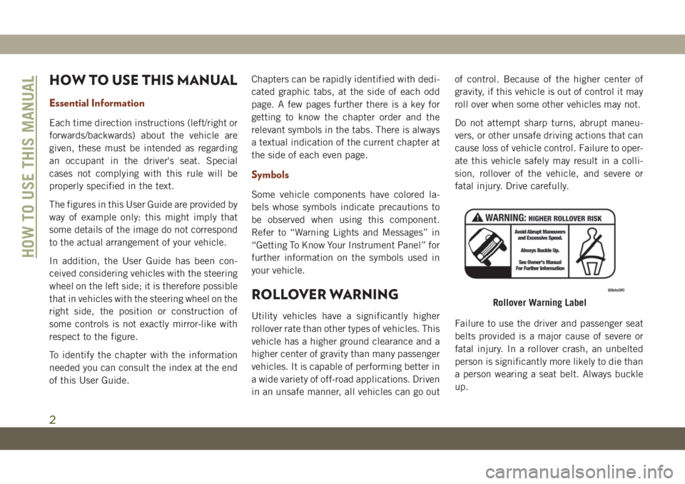
fatal injury. Drive carefully.
Failure to use the driver and passenger seat
belts provided is a major cause of severe or
fatal injury. In a rollover crash, an unbelted
person is significantly more likely to die than
a person wearing a seat belt. Always buckle
up.
Rollover Warning Label
HOW TO USE THIS MANUAL
2
Page 8 of 378
WELCOME FROM FCA
HOW TO FIND YOUR OWNER’S MANUAL ONLINE.... 1
HOW TO USE THIS MANUAL
HOW TO USE THIS MANUAL............... 2Essential Information................ 2
Symbols........................ 2
ROLLOVER WARNING................... 2
WARNINGS AND CAUTIONS............... 3
VEHICLE CHANGES/ALTERATIONS............ 3
GRAPHICAL TABLE OF CONTENTS
INSTRUMENT PANEL.................. 12
INTERIOR......................... 13
GETTING TO KNOW YOUR VEHICLE
KEYS........................... 14KeyFob ....................... 14
IGNITION SWITCH.................... 15Keyless Enter-N-Go — Ignition......... 15
REMOTE STARTING SYSTEM — IF EQUIPPED.... 17How To Use Remote Start............ 17
To Enter Remote Start Mode........... 18
VEHICLE SECURITY ALARM — IF EQUIPPED..... 18To Arm The System................ 18
To Disarm The System.............. 18
Tamper Alert.................... 19
PREMIUM VEHICLE SECURITY ALARM
— IF EQUIPPED..................... 19
To Arm The System................ 19
To Disarm The System.............. 20
Security System Manual Override........ 21
DOORS.......................... 21Keyless Enter-N-Go — Passive Entry...... 21
Child-Protection Door Lock System
— Rear Doors................... 24
SEATS .......................... 25Driver Memory Seat — If Equipped....... 25
Heated Seats.................... 28
Front Ventilated Seats.............. 29
HEAD RESTRAINTS................... 30Supplemental Active Head Restraints
— Front Seats................... 30
Adjustment — Rear Seats............ 32
Head Restraint Removal — Rear Seats.... 32
STEERING WHEEL.................... 33Manual Tilt/Telescoping Steering Column
— If Equipped................... 33
Power Tilt/Telescoping Steering Column
— If Equipped................... 34
Heated Steering Wheel — If Equipped..... 34
MIRRORS........................ 35Power Folding Outside Mirrors
— If Equipped................... 35
Tilt Side Mirrors In Reverse (Available With
Memory Seat Only) — If Equipped....... 36
EXTERIOR LIGHTS................... 36Headlight Switch.................. 36
Multifunction Lever................ 37
Daytime Running Lights — If Equipped.... 37
High/Low Beam Switch.............. 38
Automatic High Beam — If Equipped..... 38
Flash-To-Pass................... 38
Automatic Headlights — If Equipped..... 38
Parking Lights And Panel Lights........ 39
Headlights On Automatically With Wipers . . . 39Adaptive Bi-Xenon High Intensity Discharge
Headlights — If Equipped............ 39
Headlight Delay.................. 39
Lights-On Reminder................ 40
Front And Rear Fog Lights — If Equipped . . . 40
Turn Signals.................... 40
Automatic Headlight Leveling — HID Headlights
Only......................... 40
Battery Saver.................... 40
WINDSHIELD WIPERS AND WASHERS......... 41Windshield Wiper Operation........... 41
Rain Sensing Wipers — If Equipped...... 42
Rear Window Wiper/Washer........... 43
CLIMATE CONTROLS.................. 43Automatic Climate Controls Overview..... 44
Climate Control Functions............ 50
Automatic Temperature Control (ATC)..... 50
Operating Tips................... 51
WINDOWS........................ 52Power Window Controls.............. 52
Auto-Down Feature................ 52
Auto-Up Feature With Anti-Pinch Protection . 53
Window Lockout Switch............. 53
Wind Buffeting.................. 53
POWER SUNROOF — IF EQUIPPED........... 54Opening Sunroof.................. 54
Closing Sunroof.................. 54
Sunshade Operation................ 55
Pinch Protect Feature............... 55
Venting Sunroof — Express........... 55
Sunroof Maintenance............... 55
Relearn Procedure................. 55
TABLE OF CONTENTS
6
Page 9 of 378
COMMANDVIEW SUNROOF WITH POWER SHADE — IF
EQUIPPED........................ 56
Opening Sunroof.................. 57
Closing Sunroof.................. 57
Opening Power Shade............... 57
Closing Power Shade............... 58
Pinch Protect Feature............... 58
Venting Sunroof — Express........... 58
Sunroof Maintenance............... 58
HOOD.......................... 59To Open The Hood................. 59
To Close The Hood................. 59
LIFTGATE......................... 59Opening....................... 59
Closing........................ 60
Power Liftgate — If Equipped......... 61
INTERNAL EQUIPMENT................. 62Power Outlets.................... 62
ROOF LUGGAGE RACK — IF EQUIPPED......... 64
GETTING TO KNOW YOUR
INSTRUMENT PANEL
INSTRUMENT CLUSTER DISPLAY............ 66Instrument Cluster Display Location And
Controls....................... 66
Oil Change Indicator System — If Equipped . 67
Instrument Cluster Display Selectable Items . 67
Display Menu items................ 67
Diesel Displays — If Equipped......... 68
Diesel Particulate Filter (DPF) Messages — If
Equipped...................... 69
Fuel System Messages — If Equipped..... 70
TRIP COMPUTER..................... 73WARNING LIGHTS AND MESSAGES.......... 73
Red Warning Lights................ 73
Yellow Warning Lights............... 76
Yellow Indicator Lights.............. 80
Green Indicator Lights.............. 82
White Indicator Lights.............. 83
Blue Indicator Lights............... 84
ONBOARD DIAGNOSTIC SYSTEM — OBD II...... 85Onboard Diagnostic System (OBD II)
Cybersecurity.................... 85
SAFETY
SAFETY FEATURES................... 86Anti-Lock Brake System (ABS)......... 86
Electronic Brake Control System........ 87
AUXILIARY DRIVING SYSTEMS............. 97Blind Spot Monitoring (BSM) — If Equipped . 97
Forward Collision Warning (FCW) With
Mitigation..................... 101
Tire Pressure Monitor System (TPMS).... 103
OCCUPANT RESTRAINT SYSTEMS.......... 107Occupant Restraint Systems Features.... 107
Important Safety Precautions......... 107
Seat Belt Systems................ 108
Supplemental Restraint Systems (SRS) . . . 117
Child Restraints — Carrying Children
Safely....................... 127
Transporting Pets................ 140
SAFETY TIPS..................... 140Transporting Passengers............ 140
Exhaust Gas................... 141
Safety Checks You Should Make Inside The
Vehicle...................... 141
Periodic Safety Checks You Should Make
Outside The Vehicle............... 143
STARTING AND OPERATING
STARTING THE ENGINE — GAS............ 145Automatic Transmission............. 145
Normal Starting................. 145
STARTING THE ENGINE — 3.0L DIESEL ENGINE . . 148Automatic Transmission............. 149
Normal Starting................. 149
STOP/START SYSTEM — IF EQUIPPED........ 150Automatic Mode................. 150
Possible Reasons The Engine Does Not
Autostop..................... 151
To Start The Engine While In Autostop Mode . . 151To Manually Turn Off The Stop/Start
System...................... 152
T
o Manually Turn On The Stop/Start System . . 152System Malfunction............... 152
ENGINE BREAK-IN RECOMMENDATIONS....... 1523.6L & 5.7L Engines.............. 152
Diesel Engine................... 153
SRT Engines................... 153
AUTOMATIC TRANSMISSION............. 154Ignition Park Interlock.............. 155
Brake/Transmission Shift Interlock System . 156
Fuel Economy (ECO) Mode........... 156
Eight–Speed Automatic Transmission..... 157
SPORT MODE — IF EQUIPPED............ 159
FOUR WHEEL DRIVE OPERATION........... 159
Quadra-Trac I Operating Instructions/Precautions
— If Equipped.................. 159
Quadra-Trac II Operating Instructions/Precautions
— If Equipped.................. 159
Shift Positions.................. 160
Shifting Procedures............... 161
Quadra-Drive II System — If Equipped.... 163
7
Page 31 of 378
WARNING!
heater. It may cause burns even at low
temperatures, especially if used for long
periods of time.
• Do not place anything on the seat or
seatback that insulates against heat,
such as a blanket or cushion. This may
cause the seat heater to overheat. Sit-
ting in a seat that has been overheated
could cause serious burns due to the
increased surface temperature of the
seat.
Rear Heated Seats — If Equipped
On some models, the two rear outboard seats
may be equipped with heated seats. There
are two heated seat switches that allow the
rear passengers to operate the seats indepen-
dently. The heated seat switches for each
heater are located on the rear of the center
console.
You can choose from HI, LO, or OFF heat
settings. Amber indicator lights in each
switch indicate the level of heat in use. Two
indicator lights will illuminate for HI, one for
LO and none for OFF.• Push the switch
once to turn the HI
setting on.
• Push the switch
a second time to turn
the LO setting on.
• Push the switch
a third time to turn the
heating elements off.
The level of heat selected will stay on until
the operator changes it.
WARNING!
•Persons who are unable to feel pain to the
skin because of advanced age, chronic ill-
ness, diabetes, spinal cord injury, medica-
tion, alcohol use, exhaustion or other
physical condition must exercise care
when using the seat heater. It may cause
burns even at low temperatures, especially
if used for long periods of time.
•Do not place anything on the seat or seat-
back that insulates against heat, such as a
blanket or cushion. This may cause the
seat heater to overheat. Sitting in a seat
that has been overheated could cause se-
rious burns due to the increased surface
temperature of the seat.
Front Ventilated Seats
If your vehicle is equipped with ventilated
seats, the seat cushion and seat back will
have fans that draw the air from the passen-
ger compartment and move air through fine
perforations in the seat cover to help keep the
driver and front passenger cooler in higher
ambient temperatures. The fans operate at
two speeds, HI and LO.
The front ventilated seats control buttons are
located within the Uconnect system. You can
gain access to the control buttons through
the climate screen or the controls screen.
• Press the ventilated seat button
once
to choose HI.
• Press the ventilated seat button
a
second time to choose LO.
• Press the ventilated seat button
a third
time to turn the ventilated seat off.
NOTE:
The engine must be running for the ventilated
seats to operate.
29
Page 55 of 378
Push the window switch down for half a
second and release. The window will go down
automatically.
To stop the window from going all the way
down during the Auto-Down operation, pull
up or push down on the switch briefly.
To open the window part way (manually),
push the window switch down briefly and
release.
Auto-Up Feature With Anti-Pinch
Protection
NOTE:
• If the window runs into any obstacle during
auto-closure, it will reverse direction and
then go back down. Remove the obstacle
and use the window switch again to close
the window.
• Any impact due to rough road conditions
may trigger the auto-reverse function unex-
pectedly during auto-closure. If this hap-
pens, pull the switch lightly and hold to
close the window manually.
WARNING!
There is no anti-pinch protection when the
window is almost closed. To avoid personal
injury be sure to clear your arms, hands,
fingers and all objects from the window
path before closing.
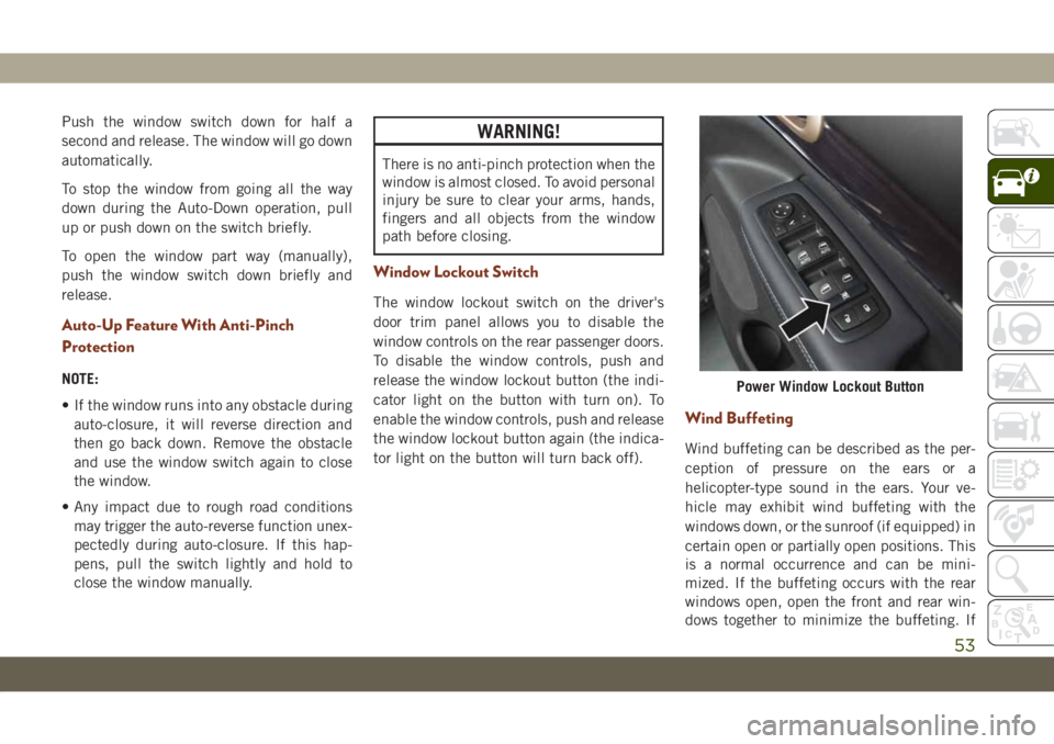
Window Lockout Switch
The window lockout switch on the driver's
door trim panel allows you to disable the
window controls on the rear passenger doors.
To disable the window controls, push and
release the window lockout button (the indi-
cator light on the button with turn on). To
enable the window controls, push and release
the window lockout button again (the indica-
tor light on the button will turn back off).
Wind Buffeting
Wind buffeting can be described as the per-
ception of pressure on the ears or a
helicopter-type sound in the ears. Your ve-
hicle may exhibit wind buffeting with the
windows down, or the sunroof (if equipped) in
certain open or partially open positions. This
is a normal occurrence and can be mini-
mized. If the buffeting occurs with the rear
windows open, open the front and rear win-
dows together to minimize the buffeting. If
Power Window Lockout Button
53
Page 64 of 378
• The power liftgate will not operate in tem-
peratures below −22°F (−30°C) or tem-
peratures above 150° F (65° C). Be sure to
remove any buildup of snow or ice from the
liftgate before pushing any of the power
liftgate switches.
• If anything obstructs the power liftgate
while it is closing or opening, the liftgate
will automatically reverse to the closed or
open position, provided it meets sufficient
resistance.
• There are also pinch sensors attached to
the side of the liftgate. Light pressure any-
where along these strips will cause the
liftgate to return to the open position.
• If the liftgate is not fully open, push the
liftgate button on the key fob twice to
operate the liftgate.
• If the electronic liftgate release is pushed
while the power liftgate is closing, the lift-
gate will reverse to the full open position.• If the electronic liftgate release is pushed
while the power liftgate is opening, the
liftgate motor will disengage to allow
manual operation.
• If the power liftgate encounters multiple
obstructions within the same cycle, the
system will automatically stop and the lift-
gate must be opened or closed manually.
WARNING!
• Driving with the liftgate open can allow
poisonous exhaust gases into your ve-
hicle. You and your passengers could be
injured by these fumes. Keep the liftgate
closed when you are operating the
vehicle.
• If you are required to drive with the
liftgate open, make sure that all win-
dows are closed, and the climate control
blower switch is set at high speed. Do
not use the recirculation mode.
INTERNAL EQUIPMENT
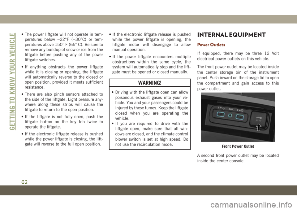
Power Outlets
If equipped, there may be three 12 Volt
electrical power outlets on this vehicle.
The front power outlet may be located inside
the center storage bin of the instrument
panel. Push inward on the storage lid to open
the compartment and gain access to this
power outlet.
A second front power outlet may be located
inside the center console.
Front Power Outlet
GETTING TO KNOW YOUR VEHICLE
62
Page 66 of 378
CAUTION!
• Power outlets are designed for accessory
plugs only. Do not insert any other object
in the power outlets as this will damage
the outlet and blow the fuse. Improper
use of the power outlet can cause dam-
age not covered by your New Vehicle
Limited Warranty.
WARNING!
To avoid serious injury or death:
• Do not insert any objects into the
receptacles.
• Do not touch with wet hands.
• Close the lid when not in use.
• If this outlet is mishandled, it may
cause an electric shock and failure.
CAUTION!
•Many accessories that can be plugged in
draw power from the vehicle's battery, even
when not in use (i.e., cellular phones,
etc.). Eventually, if plugged in long
enough, the vehicle's battery will discharge
sufficiently to degrade battery life and/or
prevent the engine from starting.
• Accessories that draw higher power (i.e.,
coolers, vacuum cleaners, lights, etc.),
will degrade the battery even more
quickly. Only use these intermittently
and with greater caution.
• After the use of high power draw acces-
sories, or long periods of the vehicle not
being started (with accessories still
plugged in), the vehicle must be driven a
sufficient length of time to allow the
alternator to recharge the vehicle's
battery.
• Power outlets are designed for accessory
plugs only. Do not hang any type of
accessory or accessory bracket from the
plug. Improper use of the power outlet
can cause damage.
ROOF LUGGAGE RACK — IF
EQUIPPED
The crossbars and siderails are designed to
carry the weight on vehicles equipped with a
luggage rack. The load must not exceed
150 lbs (68 kg), and should be uniformly
distributed over the luggage rack crossbars.
NOTE:
If not equipped with crossbars, your autho-
rized dealer can order and install Mopar
crossbars built specifically for this roof rack
system.
Distribute cargo weight evenly on the roof
rack crossbars. The roof rack does not in-
crease the total load carrying capacity of the
vehicle. Be sure the total load of cargo inside
the vehicle plus that on the external rack
does not exceed the maximum vehicle load
capacity.
To move the crossbars, loosen the attach-
ments, located at the upper edge of each
crossbar, approximately eight turns using the
anti-theft wrench provided with the Mopar
crossbars. Then, move the crossbar to the
desired position, keeping the crossbars par-
GETTING TO KNOW YOUR VEHICLE
64
Page 71 of 378
• Engine Will Not Restart in XXX mi Service
AdBlue®See Dealer
• Engine Will Not Restart Service AdBlue
®
System See Dealer
• Engine Will Not Start Service AdBlue
®Sys-
tem See Dealer
Diesel Particulate Filter (DPF) Messages
— If Equipped
This engine meets all required diesel engine
emissions standards. To achieve these emis-
sions standards, your vehicle is equipped
with a state-of-the-art engine and exhaust
system. These systems are seamlessly inte-
grated into your vehicle and managed by the
Powertrain Control Module (PCM). The PCM
manages engine combustion to allow the ex-
haust system’s catalyst to trap and burn Par-
ticulate Matter (PM) pollutants, with no input
or interaction on your part.
WARNING!
A hot exhaust system can start a fire if you
park over materials that can burn. Such
materials might be grass or leaves coming
WARNING!
into contact with your exhaust system. Do
not park or operate your vehicle in areas
where your exhaust system can contact
anything that can burn.
Your vehicle has the ability to alert you to
additional maintenance required on your ve-
hicle or engine. Refer to the following mes-
sages that may be displayed on your instru-
ment cluster display:
•Exhaust Filter Nearing Full Safely Drive at
Highway Speeds to Clear— This message
will be displayed if the exhaust particulate
filter reaches 80% of its maximum storage
capacity. Under conditions of exclusive
short duration and low speed driving cycles,
your diesel engine and exhaust after-
treatment system may never reach the con-
ditions required to cleanse the filter to
remove the trapped PM. If this occurs, the
“Exhaust Filter XX% Full Safely Drive at
Highway Speeds to Remedy” message will
be displayed. If this message is displayed,
you will hear one chime to assist in alerting
you of this condition. By simply driving yourvehicle at highway speeds for up to 20 min-
utes, you can remedy the condition in the
particulate filter system and allow your die-
sel engine and exhaust after-treatment sys-
tem to cleanse the filter to remove the
trapped PM and restore the system to nor-
mal operating condition.
•Exhaust System Regeneration in Process Con-
tinue Driving— This message indicates that
the Diesel Particulate Filter (DPF) is self-
cleaning. Maintain your current driving
condition until regeneration is completed.
•Exhaust System — Regeneration Completed
— This message indicates that the Diesel
Particulate Filter (DPF) self-cleaning is
completed. If this message is displayed,
you will hear one chime to assist in alerting
you of this condition.
•Exhaust System Service Required — See
Dealer— This messages indicates regen-
eration has been disabled due to a system
malfunction. At this point the engine Pow-
ertrain Control Module (PCM) will register a
fault code, the instrument panel will dis-
play a MIL light.
69
Page 73 of 378
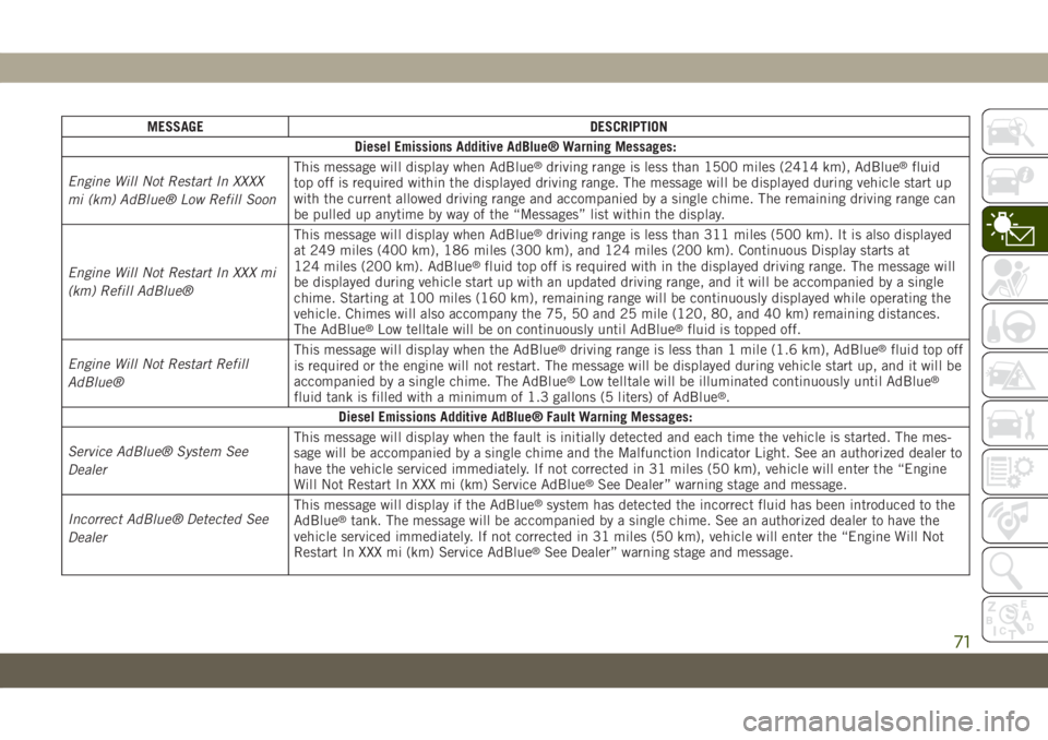
MESSAGE DESCRIPTION
Diesel Emissions Additive AdBlue® Warning Messages:
Engine Will Not Restart In XXXX
mi (km) AdBlue® Low Refill SoonThis message will display when AdBlue
®driving range is less than 1500 miles (2414 km), AdBlue®fluid
top off is required within the displayed driving range. The message will be displayed during vehicle start up
with the current allowed driving range and accompanied by a single chime. The remaining driving range can
be pulled up anytime by way of the “Messages” list within the display.
Engine Will Not Restart In XXX mi
(km) Refill AdBlue®This message will display when AdBlue
®driving range is less than 311 miles (500 km). It is also displayed
at 249 miles (400 km), 186 miles (300 km), and 124 miles (200 km). Continuous Display starts at
124 miles (200 km). AdBlue
®fluid top off is required with in the displayed driving range. The message will
be displayed during vehicle start up with an updated driving range, and it will be accompanied by a single
chime. Starting at 100 miles (160 km), remaining range will be continuously displayed while operating the
vehicle. Chimes will also accompany the 75, 50 and 25 mile (120, 80, and 40 km) remaining distances.
The AdBlue
®Low telltale will be on continuously until AdBlue®fluid is topped off.
Engine Will Not Restart Refill
AdBlue®This message will display when the AdBlue®driving range is less than 1 mile (1.6 km), AdBlue®fluid top off
is required or the engine will not restart. The message will be displayed during vehicle start up, and it will be
accompanied by a single chime. The AdBlue
®Low telltale will be illuminated continuously until AdBlue®
fluid tank is filled with a minimum of 1.3 gallons (5 liters) of AdBlue®.
Diesel Emissions Additive AdBlue® Fault Warning Messages:
Service AdBlue® System See
DealerThis message will display when the fault is initially detected and each time the vehicle is started. The mes-
sage will be accompanied by a single chime and the Malfunction Indicator Light. See an authorized dealer to
have the vehicle serviced immediately. If not corrected in 31 miles (50 km), vehicle will enter the “Engine
Will Not Restart In XXX mi (km) Service AdBlue
®See Dealer” warning stage and message.
Incorrect AdBlue® Detected See
DealerThis message will display if the AdBlue®system has detected the incorrect fluid has been introduced to the
AdBlue®tank. The message will be accompanied by a single chime. See an authorized dealer to have the
vehicle serviced immediately. If not corrected in 31 miles (50 km), vehicle will enter the “Engine Will Not
Restart In XXX mi (km) Service AdBlue
®See Dealer” warning stage and message.
71
Page 75 of 378
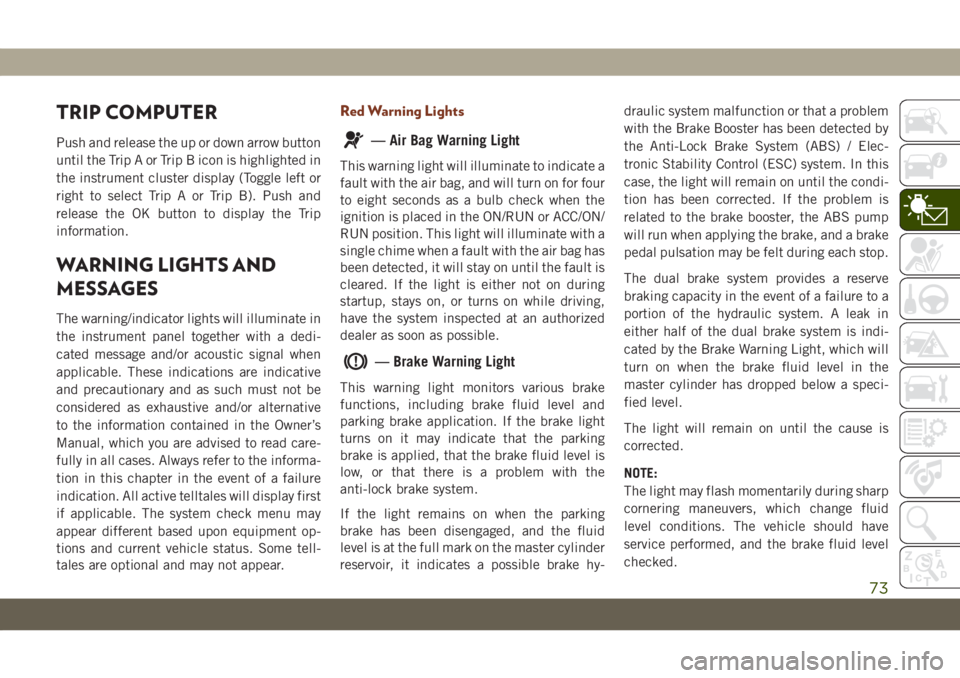
TRIP COMPUTER
Push and release the up or down arrow button
until the Trip A or Trip B icon is highlighted in
the instrument cluster display (Toggle left or
right to select Trip A or Trip B). Push and
release the OK button to display the Trip
information.
WARNING LIGHTS AND
MESSAGES
The warning/indicator lights will illuminate in
the instrument panel together with a dedi-
cated message and/or acoustic signal when
applicable. These indications are indicative
and precautionary and as such must not be
considered as exhaustive and/or alternative
to the information contained in the Owner’s
Manual, which you are advised to read care-
fully in all cases. Always refer to the informa-
tion in this chapter in the event of a failure
indication. All active telltales will display first
if applicable. The system check menu may
appear different based upon equipment op-
tions and current vehicle status. Some tell-
tales are optional and may not appear.
Red Warning Lights
— Air Bag Warning Light
This warning light will illuminate to indicate a
fault with the air bag, and will turn on for four
to eight seconds as a bulb check when the
ignition is placed in the ON/RUN or ACC/ON/
RUN position. This light will illuminate with a
single chime when a fault with the air bag has
been detected, it will stay on until the fault is
cleared. If the light is either not on during
startup, stays on, or turns on while driving,
have the system inspected at an authorized
dealer as soon as possible.
— Brake Warning Light
This warning light monitors various brake
functions, including brake fluid level and
parking brake application. If the brake light
turns on it may indicate that the parking
brake is applied, that the brake fluid level is
low, or that there is a problem with the
anti-lock brake system.
If the light remains on when the parking
brake has been disengaged, and the fluid
level is at the full mark on the master cylinder
reservoir, it indicates a possible brake hy-draulic system malfunction or that a problem
with the Brake Booster has been detected by
the Anti-Lock Brake System (ABS) / Elec-
tronic Stability Control (ESC) system. In this
case, the light will remain on until the condi-
tion has been corrected. If the problem is
related to the brake booster, the ABS pump
will run when applying the brake, and a brake
pedal pulsation may be felt during each stop.
The dual brake system provides a reserve
braking capacity in the event of a failure to a
portion of the hydraulic system. A leak in
either half of the dual brake system is indi-
cated by the Brake Warning Light, which will
turn on when the brake fluid level in the
master cylinder has dropped below a speci-
fied level.
The light will remain on until the cause is
corrected.
NOTE:
The light may flash momentarily during sharp
cornering maneuvers, which change fluid
level conditions. The vehicle should have
service performed, and the brake fluid level
checked.
73