width JEEP GRAND CHEROKEE 2020 Owner handbook (in English)
[x] Cancel search | Manufacturer: JEEP, Model Year: 2020, Model line: GRAND CHEROKEE, Model: JEEP GRAND CHEROKEE 2020Pages: 378, PDF Size: 6.88 MB
Page 100 of 378

When the vehicle is started, the BSM warning
light will momentarily illuminate in both out-
side rear view mirrors to let the driver know
that the system is operational. The BSM
system sensors operate when the vehicle is in
any forward gear or REVERSE.
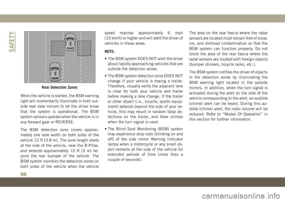
The BSM detection zone covers approxi-
mately one lane width on both sides of the
vehicle 12 ft (3.8 m). The zone length starts
at the side of the vehicle, near the B-Pillar,
and extends approximately 10 ft (3 m) be-
yond the rear bumper of the vehicle. The
BSM system monitors the detection zones on
both sides of the vehicle when the vehiclespeed reaches approximately 6 mph
(10 km/h) or higher and will alert the driver of
vehicles in these areas.
NOTE:
• The BSM system DOES NOT alert the driver
about rapidly approaching vehicles that are
outside the detection zones.
• The BSM system detection zone DOES NOT
change if your vehicle is towing a trailer.
Therefore, visually verify the adjacent lane
is clear for both your vehicle and trailer
before making a lane change. If the trailer
or other object (i.e., bicycle, sports equip-
ment) extends beyond the side of your ve-
hicle, this may result in random false de-
tections on the trailer, and false chimes
when the turn signal is used.
• The Blind Spot Monitoring (BSM) system
may experience drop outs (blinking on and
off) of the side mirror Warning Indicator
lamps when a motorcycle or any small ob-
ject remains at the side of the vehicle for
extended periods of time (more than a
couple of seconds).The area on the rear fascia where the radar
sensors are located must remain free of snow,
ice, and dirt/road contamination so that the
BSM system can function properly. Do not
block the area of the rear fascia where the
radar sensors are located with foreign objects
(bumper stickers, bicycle racks, etc.).
The BSM system notifies the driver of objects
in the detection zones by illuminating the
BSM warning light located in the outside
mirrors. In addition, when the turn signal is
activated during the alert on the side of the
vehicle corresponding to the alert, an audible
(chime) alert can be heard. During this au-
dible (chime) alert, the radio volume will be
reduced. Refer to “Modes Of Operation” in
this section for further information.
Rear Detection Zones
SAFETY
98
Page 186 of 378

PARKVIEW REAR BACK UP
CAMERA — IF EQUIPPED
The ParkView Rear Back Up Camera allows
you to see an on-screen image of the rear
surroundings of your vehicle whenever the
gear selector is put into REVERSE. The im-
age will be displayed on the Navigation/
Multimedia radio display screen along with a
caution note to “check entire surroundings”
across the top of the screen. After five sec-
onds this note will disappear. The ParkView
camera is located on the rear of the vehicle
above the rear license plate.
When the vehicle is shifted out of REVERSE
(with camera delay turned off), the rear cam-
era mode is exited and the navigation or
audio screen appears again.Manual Activation Of The Rear View Camera
1. Press the “Controls” button located on
the bottom of the Uconnect display.
2. Press the “Backup Camera” button to
turn the Rear View Camera system on.
NOTE:
The ParkView Rear Back Up Camera has
programmable modes of operation that may
be selected through the Uconnect System.
Refer to “Uconnect Settings” in “Multime-
dia” in your Owner’s Manual for further infor-
mation.
When the vehicle is shifted out of REVERSE
(with camera delay turned off), the rear cam-
era mode is exited and the previous screen
appears again. When the vehicle is shifted
out of REVERSE (with camera delay turnedon), the camera image will continue to be
displayed for up to ten seconds after shifting
out of REVERSE unless the vehicle speed
exceeds 8 mph (13 km/h), the vehicle is
shifted into PARK, the vehicle’s ignition is
cycled to the OFF position, or the user
presses image defeat [X] to exit out of the
camera video display.
When enabled, active guide lines are overlaid
on the image to illustrate the width of the
vehicle and its projected backup path based
on the steering wheel position. A dashed
center line overlay indicates the center of the
vehicle to assist with parking or aligning to a
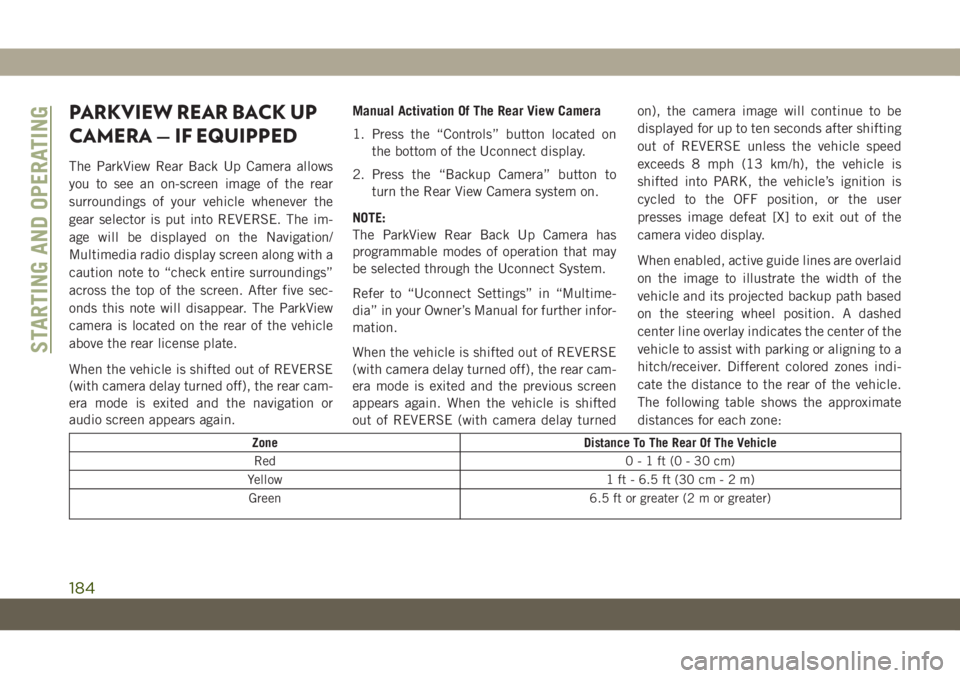
hitch/receiver. Different colored zones indi-
cate the distance to the rear of the vehicle.
The following table shows the approximate
distances for each zone:
Zone Distance To The Rear Of The Vehicle
Red 0-1ft(0-30cm)
Yellow 1 ft - 6.5 ft (30 cm-2m)
Green 6.5 ft or greater (2 m or greater)
STARTING AND OPERATING
184
Page 281 of 378

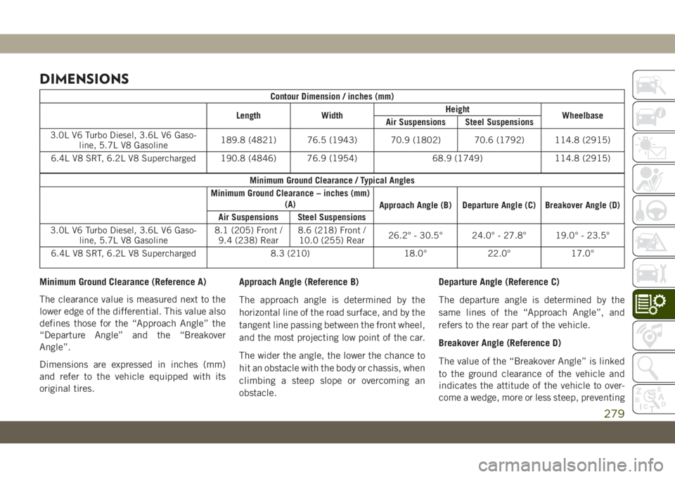
DIMENSIONS
Contour Dimension / inches (mm)
Length WidthHeight
Wheelbase
Air Suspensions Steel Suspensions
3.0L V6 Turbo Diesel, 3.6L V6 Gaso-
line, 5.7L V8 Gasoline189.8 (4821) 76.5 (1943) 70.9 (1802) 70.6 (1792) 114.8 (2915)
6.4L V8 SRT, 6.2L V8 Supercharged 190.8 (4846) 76.9 (1954) 68.9 (1749) 114.8 (2915)
Minimum Ground Clearance / Typical Angles
Minimum Ground Clearance – inches (mm)
(A)
Approach Angle (B) Departure Angle (C) Breakover Angle (D)
Air Suspensions Steel Suspensions
3.0L V6 Turbo Diesel, 3.6L V6 Gaso-
line, 5.7L V8 Gasoline8.1 (205) Front /
9.4 (238) Rear8.6 (218) Front /
10.0 (255) Rear26.2° - 30.5° 24.0° - 27.8° 19.0° - 23.5°
6.4L V8 SRT, 6.2L V8 Supercharged 8.3 (210) 18.0° 22.0° 17.0°
Minimum Ground Clearance (Reference A)
The clearance value is measured next to the
lower edge of the differential. This value also
defines those for the “Approach Angle” the
“Departure Angle” and the “Breakover
Angle”.
Dimensions are expressed in inches (mm)
and refer to the vehicle equipped with its
original tires.Approach Angle (Reference B)
The approach angle is determined by the
horizontal line of the road surface, and by the
tangent line passing between the front wheel,
and the most projecting low point of the car.
The wider the angle, the lower the chance to
hit an obstacle with the body or chassis, when
climbing a steep slope or overcoming an
obstacle.Departure Angle (Reference C)
The departure angle is determined by the
same lines of the “Approach Angle”, and
refers to the rear part of the vehicle.
Breakover Angle (Reference D)
The value of the “Breakover Angle” is linked
to the ground clearance of the vehicle and
indicates the attitude of the vehicle to over-
come a wedge, more or less steep, preventing
279