warning lights JEEP GRAND CHEROKEE 2021 Owner handbook (in English)
[x] Cancel search | Manufacturer: JEEP, Model Year: 2021, Model line: GRAND CHEROKEE, Model: JEEP GRAND CHEROKEE 2021Pages: 378, PDF Size: 6.88 MB
Page 4 of 378
HOW TO USE THIS MANUAL
Essential Information
Each time direction instructions (left/right or
forwards/backwards) about the vehicle are
given, these must be intended as regarding
an occupant in the driver's seat. Special
cases not complying with this rule will be
properly specified in the text.
The figures in this User Guide are provided by
way of example only: this might imply that
some details of the image do not correspond
to the actual arrangement of your vehicle.
In addition, the User Guide has been con-
ceived considering vehicles with the steering
wheel on the left side; it is therefore possible
that in vehicles with the steering wheel on the
right side, the position or construction of
some controls is not exactly mirror-like with
respect to the figure.
To identify the chapter with the information
needed you can consult the index at the end
of this User Guide.Chapters can be rapidly identified with dedi-
cated graphic tabs, at the side of each odd
page. A few pages further there is a key for
getting to know the chapter order and the
relevant symbols in the tabs. There is always
a textual indication of the current chapter at
the side of each even page.
Symbols
Some vehicle components have colored la-
bels whose symbols indicate precautions to
be observed when using this component.
Refer to “Warning Lights and Messages” in
“Getting To Know Your Instrument Panel” for
further information on the symbols used in
your vehicle.
ROLLOVER WARNING
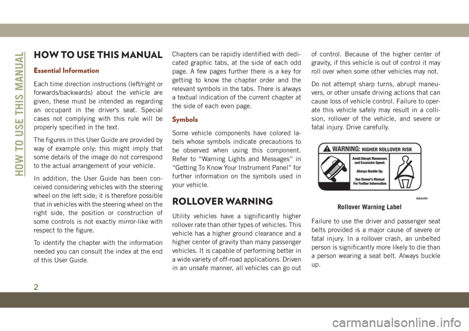
Utility vehicles have a significantly higher
rollover rate than other types of vehicles. This
vehicle has a higher ground clearance and a
higher center of gravity than many passenger
vehicles. It is capable of performing better in
a wide variety of off-road applications. Driven
in an unsafe manner, all vehicles can go outof control. Because of the higher center of
gravity, if this vehicle is out of control it may
roll over when some other vehicles may not.
Do not attempt sharp turns, abrupt maneu-
vers, or other unsafe driving actions that can
cause loss of vehicle control. Failure to oper-
ate this vehicle safely may result in a colli-
sion, rollover of the vehicle, and severe or
fatal injury. Drive carefully.
Failure to use the driver and passenger seat
belts provided is a major cause of severe or
fatal injury. In a rollover crash, an unbelted
person is significantly more likely to die than
a person wearing a seat belt. Always buckle
up.
Rollover Warning Label
HOW TO USE THIS MANUAL
2
Page 8 of 378
WELCOME FROM FCA
HOW TO FIND YOUR OWNER’S MANUAL ONLINE.... 1
HOW TO USE THIS MANUAL
HOW TO USE THIS MANUAL............... 2Essential Information................ 2
Symbols........................ 2
ROLLOVER WARNING................... 2
WARNINGS AND CAUTIONS............... 3
VEHICLE CHANGES/ALTERATIONS............ 3
GRAPHICAL TABLE OF CONTENTS
INSTRUMENT PANEL.................. 12
INTERIOR......................... 13
GETTING TO KNOW YOUR VEHICLE
KEYS........................... 14KeyFob ....................... 14
IGNITION SWITCH.................... 15Keyless Enter-N-Go — Ignition......... 15
REMOTE STARTING SYSTEM — IF EQUIPPED.... 17How To Use Remote Start............ 17
To Enter Remote Start Mode........... 18
VEHICLE SECURITY ALARM — IF EQUIPPED..... 18To Arm The System................ 18
To Disarm The System.............. 18
Tamper Alert.................... 19
PREMIUM VEHICLE SECURITY ALARM
— IF EQUIPPED..................... 19
To Arm The System................ 19
To Disarm The System.............. 20
Security System Manual Override........ 21
DOORS.......................... 21Keyless Enter-N-Go — Passive Entry...... 21
Child-Protection Door Lock System
— Rear Doors................... 24
SEATS .......................... 25Driver Memory Seat — If Equipped....... 25
Heated Seats.................... 28
Front Ventilated Seats.............. 29
HEAD RESTRAINTS................... 30Supplemental Active Head Restraints
— Front Seats................... 30
Adjustment — Rear Seats............ 32
Head Restraint Removal — Rear Seats.... 32
STEERING WHEEL.................... 33Manual Tilt/Telescoping Steering Column
— If Equipped................... 33
Power Tilt/Telescoping Steering Column
— If Equipped................... 34
Heated Steering Wheel — If Equipped..... 34
MIRRORS........................ 35Power Folding Outside Mirrors
— If Equipped................... 35
Tilt Side Mirrors In Reverse (Available With
Memory Seat Only) — If Equipped....... 36
EXTERIOR LIGHTS................... 36Headlight Switch.................. 36
Multifunction Lever................ 37
Daytime Running Lights — If Equipped.... 37
High/Low Beam Switch.............. 38
Automatic High Beam — If Equipped..... 38
Flash-To-Pass................... 38
Automatic Headlights — If Equipped..... 38
Parking Lights And Panel Lights........ 39
Headlights On Automatically With Wipers . . . 39Adaptive Bi-Xenon High Intensity Discharge
Headlights — If Equipped............ 39
Headlight Delay.................. 39
Lights-On Reminder................ 40
Front And Rear Fog Lights — If Equipped . . . 40
Turn Signals.................... 40
Automatic Headlight Leveling — HID Headlights
Only......................... 40
Battery Saver.................... 40
WINDSHIELD WIPERS AND WASHERS......... 41Windshield Wiper Operation........... 41
Rain Sensing Wipers — If Equipped...... 42
Rear Window Wiper/Washer........... 43
CLIMATE CONTROLS.................. 43Automatic Climate Controls Overview..... 44
Climate Control Functions............ 50
Automatic Temperature Control (ATC)..... 50
Operating Tips................... 51
WINDOWS........................ 52Power Window Controls.............. 52
Auto-Down Feature................ 52
Auto-Up Feature With Anti-Pinch Protection . 53
Window Lockout Switch............. 53
Wind Buffeting.................. 53
POWER SUNROOF — IF EQUIPPED........... 54Opening Sunroof.................. 54
Closing Sunroof.................. 54
Sunshade Operation................ 55
Pinch Protect Feature............... 55
Venting Sunroof — Express........... 55
Sunroof Maintenance............... 55
Relearn Procedure................. 55
TABLE OF CONTENTS
6
Page 9 of 378
COMMANDVIEW SUNROOF WITH POWER SHADE — IF
EQUIPPED........................ 56
Opening Sunroof.................. 57
Closing Sunroof.................. 57
Opening Power Shade............... 57
Closing Power Shade............... 58
Pinch Protect Feature............... 58
Venting Sunroof — Express........... 58
Sunroof Maintenance............... 58
HOOD.......................... 59To Open The Hood................. 59
To Close The Hood................. 59
LIFTGATE......................... 59Opening....................... 59
Closing........................ 60
Power Liftgate — If Equipped......... 61
INTERNAL EQUIPMENT................. 62Power Outlets.................... 62
ROOF LUGGAGE RACK — IF EQUIPPED......... 64
GETTING TO KNOW YOUR
INSTRUMENT PANEL
INSTRUMENT CLUSTER DISPLAY............ 66Instrument Cluster Display Location And
Controls....................... 66
Oil Change Indicator System — If Equipped . 67
Instrument Cluster Display Selectable Items . 67
Display Menu items................ 67
Diesel Displays — If Equipped......... 68
Diesel Particulate Filter (DPF) Messages — If
Equipped...................... 69
Fuel System Messages — If Equipped..... 70
TRIP COMPUTER..................... 73WARNING LIGHTS AND MESSAGES.......... 73
Red Warning Lights................ 73
Yellow Warning Lights............... 76
Yellow Indicator Lights.............. 80
Green Indicator Lights.............. 82
White Indicator Lights.............. 83
Blue Indicator Lights............... 84
ONBOARD DIAGNOSTIC SYSTEM — OBD II...... 85Onboard Diagnostic System (OBD II)
Cybersecurity.................... 85
SAFETY
SAFETY FEATURES................... 86Anti-Lock Brake System (ABS)......... 86
Electronic Brake Control System........ 87
AUXILIARY DRIVING SYSTEMS............. 97Blind Spot Monitoring (BSM) — If Equipped . 97
Forward Collision Warning (FCW) With
Mitigation..................... 101
Tire Pressure Monitor System (TPMS).... 103
OCCUPANT RESTRAINT SYSTEMS.......... 107Occupant Restraint Systems Features.... 107
Important Safety Precautions......... 107
Seat Belt Systems................ 108
Supplemental Restraint Systems (SRS) . . . 117
Child Restraints — Carrying Children
Safely....................... 127
Transporting Pets................ 140
SAFETY TIPS..................... 140Transporting Passengers............ 140
Exhaust Gas................... 141
Safety Checks You Should Make Inside The
Vehicle...................... 141
Periodic Safety Checks You Should Make
Outside The Vehicle............... 143
STARTING AND OPERATING
STARTING THE ENGINE — GAS............ 145Automatic Transmission............. 145
Normal Starting................. 145
STARTING THE ENGINE — 3.0L DIESEL ENGINE . . 148Automatic Transmission............. 149
Normal Starting................. 149
STOP/START SYSTEM — IF EQUIPPED........ 150Automatic Mode................. 150
Possible Reasons The Engine Does Not
Autostop..................... 151
To Start The Engine While In Autostop Mode . . 151To Manually Turn Off The Stop/Start
System...................... 152
T
o Manually Turn On The Stop/Start System . . 152System Malfunction............... 152
ENGINE BREAK-IN RECOMMENDATIONS....... 1523.6L & 5.7L Engines.............. 152
Diesel Engine................... 153
SRT Engines................... 153
AUTOMATIC TRANSMISSION............. 154Ignition Park Interlock.............. 155
Brake/Transmission Shift Interlock System . 156
Fuel Economy (ECO) Mode........... 156
Eight–Speed Automatic Transmission..... 157
SPORT MODE — IF EQUIPPED............ 159
FOUR WHEEL DRIVE OPERATION........... 159
Quadra-Trac I Operating Instructions/Precautions
— If Equipped.................. 159
Quadra-Trac II Operating Instructions/Precautions
— If Equipped.................. 159
Shift Positions.................. 160
Shifting Procedures............... 161
Quadra-Drive II System — If Equipped.... 163
7
Page 31 of 378
WARNING!
heater. It may cause burns even at low
temperatures, especially if used for long
periods of time.
• Do not place anything on the seat or
seatback that insulates against heat,
such as a blanket or cushion. This may
cause the seat heater to overheat. Sit-
ting in a seat that has been overheated
could cause serious burns due to the
increased surface temperature of the
seat.
Rear Heated Seats — If Equipped
On some models, the two rear outboard seats
may be equipped with heated seats. There
are two heated seat switches that allow the
rear passengers to operate the seats indepen-
dently. The heated seat switches for each
heater are located on the rear of the center
console.
You can choose from HI, LO, or OFF heat
settings. Amber indicator lights in each
switch indicate the level of heat in use. Two
indicator lights will illuminate for HI, one for
LO and none for OFF.• Push the switch
once to turn the HI
setting on.
• Push the switch
a second time to turn
the LO setting on.
• Push the switch
a third time to turn the
heating elements off.
The level of heat selected will stay on until
the operator changes it.
WARNING!
•Persons who are unable to feel pain to the
skin because of advanced age, chronic ill-
ness, diabetes, spinal cord injury, medica-
tion, alcohol use, exhaustion or other
physical condition must exercise care
when using the seat heater. It may cause
burns even at low temperatures, especially
if used for long periods of time.
•Do not place anything on the seat or seat-
back that insulates against heat, such as a
blanket or cushion. This may cause the
seat heater to overheat. Sitting in a seat
that has been overheated could cause se-
rious burns due to the increased surface
temperature of the seat.
Front Ventilated Seats
If your vehicle is equipped with ventilated
seats, the seat cushion and seat back will
have fans that draw the air from the passen-
ger compartment and move air through fine
perforations in the seat cover to help keep the
driver and front passenger cooler in higher
ambient temperatures. The fans operate at
two speeds, HI and LO.
The front ventilated seats control buttons are
located within the Uconnect system. You can
gain access to the control buttons through
the climate screen or the controls screen.
• Press the ventilated seat button
once
to choose HI.
• Press the ventilated seat button
a
second time to choose LO.
• Press the ventilated seat button
a third
time to turn the ventilated seat off.
NOTE:
The engine must be running for the ventilated
seats to operate.
29
Page 66 of 378
CAUTION!
• Power outlets are designed for accessory
plugs only. Do not insert any other object
in the power outlets as this will damage
the outlet and blow the fuse. Improper
use of the power outlet can cause dam-
age not covered by your New Vehicle
Limited Warranty.
WARNING!
To avoid serious injury or death:
• Do not insert any objects into the
receptacles.
• Do not touch with wet hands.
• Close the lid when not in use.
• If this outlet is mishandled, it may
cause an electric shock and failure.
CAUTION!
•Many accessories that can be plugged in
draw power from the vehicle's battery, even
when not in use (i.e., cellular phones,
etc.). Eventually, if plugged in long
enough, the vehicle's battery will discharge
sufficiently to degrade battery life and/or
prevent the engine from starting.
• Accessories that draw higher power (i.e.,
coolers, vacuum cleaners, lights, etc.),
will degrade the battery even more
quickly. Only use these intermittently
and with greater caution.
• After the use of high power draw acces-
sories, or long periods of the vehicle not
being started (with accessories still
plugged in), the vehicle must be driven a
sufficient length of time to allow the
alternator to recharge the vehicle's
battery.
• Power outlets are designed for accessory
plugs only. Do not hang any type of
accessory or accessory bracket from the
plug. Improper use of the power outlet
can cause damage.
ROOF LUGGAGE RACK — IF
EQUIPPED
The crossbars and siderails are designed to
carry the weight on vehicles equipped with a
luggage rack. The load must not exceed
150 lbs (68 kg), and should be uniformly
distributed over the luggage rack crossbars.
NOTE:
If not equipped with crossbars, your autho-
rized dealer can order and install Mopar
crossbars built specifically for this roof rack
system.
Distribute cargo weight evenly on the roof
rack crossbars. The roof rack does not in-
crease the total load carrying capacity of the
vehicle. Be sure the total load of cargo inside
the vehicle plus that on the external rack
does not exceed the maximum vehicle load
capacity.
To move the crossbars, loosen the attach-
ments, located at the upper edge of each
crossbar, approximately eight turns using the
anti-theft wrench provided with the Mopar
crossbars. Then, move the crossbar to the
desired position, keeping the crossbars par-
GETTING TO KNOW YOUR VEHICLE
64
Page 75 of 378
TRIP COMPUTER
Push and release the up or down arrow button
until the Trip A or Trip B icon is highlighted in
the instrument cluster display (Toggle left or
right to select Trip A or Trip B). Push and
release the OK button to display the Trip
information.
WARNING LIGHTS AND
MESSAGES
The warning/indicator lights will illuminate in
the instrument panel together with a dedi-
cated message and/or acoustic signal when
applicable. These indications are indicative
and precautionary and as such must not be
considered as exhaustive and/or alternative
to the information contained in the Owner’s
Manual, which you are advised to read care-
fully in all cases. Always refer to the informa-
tion in this chapter in the event of a failure
indication. All active telltales will display first
if applicable. The system check menu may
appear different based upon equipment op-
tions and current vehicle status. Some tell-
tales are optional and may not appear.
Red Warning Lights
— Air Bag Warning Light
This warning light will illuminate to indicate a
fault with the air bag, and will turn on for four
to eight seconds as a bulb check when the
ignition is placed in the ON/RUN or ACC/ON/
RUN position. This light will illuminate with a
single chime when a fault with the air bag has
been detected, it will stay on until the fault is
cleared. If the light is either not on during
startup, stays on, or turns on while driving,
have the system inspected at an authorized
dealer as soon as possible.
— Brake Warning Light
This warning light monitors various brake
functions, including brake fluid level and
parking brake application. If the brake light
turns on it may indicate that the parking
brake is applied, that the brake fluid level is
low, or that there is a problem with the
anti-lock brake system.
If the light remains on when the parking
brake has been disengaged, and the fluid
level is at the full mark on the master cylinder
reservoir, it indicates a possible brake hy-draulic system malfunction or that a problem
with the Brake Booster has been detected by
the Anti-Lock Brake System (ABS) / Elec-
tronic Stability Control (ESC) system. In this
case, the light will remain on until the condi-
tion has been corrected. If the problem is
related to the brake booster, the ABS pump
will run when applying the brake, and a brake
pedal pulsation may be felt during each stop.
The dual brake system provides a reserve
braking capacity in the event of a failure to a
portion of the hydraulic system. A leak in
either half of the dual brake system is indi-
cated by the Brake Warning Light, which will
turn on when the brake fluid level in the
master cylinder has dropped below a speci-
fied level.
The light will remain on until the cause is
corrected.
NOTE:
The light may flash momentarily during sharp
cornering maneuvers, which change fluid
level conditions. The vehicle should have
service performed, and the brake fluid level
checked.
73
Page 78 of 378
ACC/ON/RUN position and if the driver’s seat
belt is unbuckled, a chime will sound and the
light will turn on. When driving, if the driver
or front passenger seat belt remains unbuck-
led, the Seat Belt Reminder Light will flash or
remain on continuously and a chime will
sound.
Refer to “Occupant Restraint Systems” in
“Safety” for further information.
— Transmission Temperature Warning
Light — If Equipped
This warning light will illuminate to warn of a
high transmission fluid temperature. This
may occur with strenuous usage such as
trailer towing. If this light turns on, stop the
vehicle and run the engine at idle or slightly
faster, with the transmission in PARK or
NEUTRAL, until the light turns off. Once the
light turns off, you may continue to drive
normally.
WARNING!
If you continue operating the vehicle when
the Transmission Temperature Warning
Light is illuminated you could cause the
fluid to boil over, come in contact with hot
engine or exhaust components and cause
a fire.
CAUTION!
Continuous driving with the Transmission
Temperature Warning Light illuminated
will eventually cause severe transmission
damage or transmission failure.
— Vehicle Security Warning Light — If
Equipped
This light will flash at a fast rate for approxi-
mately 15 seconds when the vehicle security
alarm is arming, and then will flash slowly
until the vehicle is disarmed.
Yellow Warning Lights
— Service Adaptive Cruise Control
Warning Light
This light will turn on when the ACC system is
not operating and needs service. For further
information, refer to “Adaptive Cruise Control
(ACC)” in “Starting And Operating.”
— Anti-Lock Brake (ABS) Warning
Light
This warning light monitors the Anti-Lock
Brake System (ABS). The light will turn on
when the ignition is placed in the ON/RUN or
ACC/ON/RUN position and may stay on for as
long as four seconds.
If the ABS light remains on or turns on while
driving, then the Anti-Lock portion of the
brake system is not functioning and service is
required as soon as possible. However, the
conventional brake system will continue to
operate normally, assuming the Brake Warn-
ing Light is not also on.
GETTING TO KNOW YOUR INSTRUMENT PANEL
76
Page 82 of 378
hicle start-ups as long as the malfunction
exists. When the malfunction indicator is
illuminated, the system may not be able to
detect or signal low tire pressure as intended.
TPMS malfunctions may occur for a variety of
reasons, including the installation of replace-
ment or alternate tires or wheels on the ve-
hicle that prevent the TPMS from functioning
properly. Always check the TPMS malfunc-
tion telltale after replacing one or more tires
or wheels on your vehicle to ensure that the
replacement or alternate tires and wheels
allow the TPMS to continue to function
properly.
CAUTION!
The TPMS has been optimized for the
original equipment tires and wheels.
TPMS pressures and warning have been
established for the tire size equipped on
your vehicle. Undesirable system opera-
tion or sensor damage may result when
using replacement equipment that is not
of the same size, type, and/or style. After-
market wheels can cause sensor damage.
Using aftermarket tire sealants may cause
CAUTION!
the Tire Pressure Monitoring System
(TPMS) sensor to become inoperable. Af-
ter using an aftermarket tire sealant it is
recommended that you take your vehicle
to your authorized dealer to have your
sensor function checked.
The system only warns the tire pressure is
low: it is not able to inflate them.
Yellow Indicator Lights
— Air Suspension Active Indicator
Light — If Equipped
This light will illuminate when the air suspen-
sion system is actively adjusting the ride
height.
— Air Suspension Entry/Exit Indica-
tor Light— If Equipped
This light will illuminate when the vehicle is
automatically lowered from ride height posi-
tion downward for easy entry and exit of the
vehicle.
— Air Suspension Aerody-
namic Height Indicator Light— If Equipped
This light will illuminate when the air suspen-
sion system is set to the Aerodynamic setting.
— Air Suspension Off-
Road 1 Indicator Light — If Equipped
This light will illuminate when the air suspen-
sion system is set to the Off-Road 1 setting.
— Air Suspension Off-
Road 2 Indicator Light — If Equipped
This light will illuminate when the air suspen-
sion system is set to the Off-Road 2 setting.
— Forward Collision Warning Off Indi-
cator Light — If Equipped
This indicator light illuminates to indicate
that Forward Collision Warning is off.
— 4WD Low Indicator Light — If
Equipped
This light alerts the driver that the vehicle is
in the four-wheel drive LOW mode. The front
and rear driveshafts are mechanically locked
together forcing the front and rear wheels toGETTING TO KNOW YOUR INSTRUMENT PANEL
80
Page 85 of 378
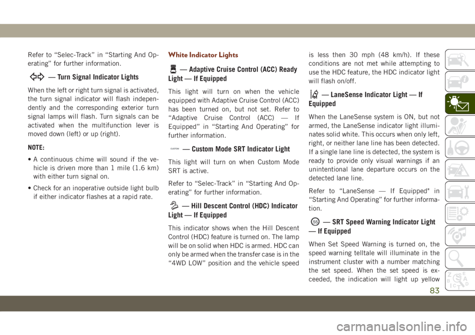
Refer to “Selec-Track” in “Starting And Op-
erating” for further information.
— Turn Signal Indicator Lights
When the left or right turn signal is activated,
the turn signal indicator will flash indepen-
dently and the corresponding exterior turn
signal lamps will flash. Turn signals can be
activated when the multifunction lever is
moved down (left) or up (right).
NOTE:
• A continuous chime will sound if the ve-
hicle is driven more than 1 mile (1.6 km)
with either turn signal on.
• Check for an inoperative outside light bulb
if either indicator flashes at a rapid rate.
White Indicator Lights
— Adaptive Cruise Control (ACC) Ready
Light — If Equipped
This light will turn on when the vehicle
equipped with Adaptive Cruise Control (ACC)
has been turned on, but not set. Refer to
“Adaptive Cruise Control (ACC) — If
Equipped” in “Starting And Operating” for
further information.
— Custom Mode SRT Indicator Light
This light will turn on when Custom Mode
SRT is active.
Refer to “Selec-Track” in “Starting And Op-
erating” for further information.
— Hill Descent Control (HDC) Indicator
Light — If Equipped
This indicator shows when the Hill Descent
Control (HDC) feature is turned on. The lamp
will be on solid when HDC is armed. HDC can
only be armed when the transfer case is in the
“4WD LOW” position and the vehicle speedis less then 30 mph (48 km/h). If these
conditions are not met while attempting to
use the HDC feature, the HDC indicator light
will flash on/off.
— LaneSense Indicator Light — If
Equipped
When the LaneSense system is ON, but not
armed, the LaneSense indicator light illumi-
nates solid white. This occurs when only left,
right, or neither lane line has been detected.
If a single lane line is detected, the system is
ready to provide only visual warnings if an
unintentional lane departure occurs on the
detected lane line.
Refer to “LaneSense — If Equipped" in
“Starting And Operating” for further informa-
tion.
— SRT Speed Warning Indicator Light
— If Equipped
When Set Speed Warning is turned on, the
speed warning telltale will illuminate in the
instrument cluster with a number matching
the set speed. When the set speed is ex-
ceeded, the indication will light up yellow
83
Page 86 of 378
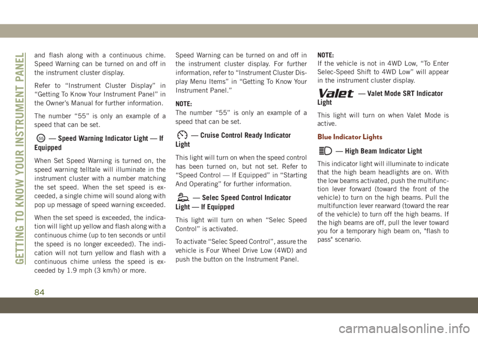
and flash along with a continuous chime.
Speed Warning can be turned on and off in
the instrument cluster display.
Refer to “Instrument Cluster Display” in
“Getting To Know Your Instrument Panel” in
the Owner’s Manual for further information.
The number “55” is only an example of a
speed that can be set.
— Speed Warning Indicator Light — If
Equipped
When Set Speed Warning is turned on, the
speed warning telltale will illuminate in the
instrument cluster with a number matching
the set speed. When the set speed is ex-
ceeded, a single chime will sound along with
pop up message of speed warning exceeded.
When the set speed is exceeded, the indica-
tion will light up yellow and flash along with a
continuous chime (up to ten seconds or until
the speed is no longer exceeded). The indi-
cation will not turn yellow and flash with a
continuous chime unless the speed is ex-
ceeded by 1.9 mph (3 km/h) or more.Speed Warning can be turned on and off in
the instrument cluster display. For further
information, refer to “Instrument Cluster Dis-
play Menu Items” in “Getting To Know Your
Instrument Panel.”
NOTE:
The number “55” is only an example of a
speed that can be set.
— Cruise Control Ready Indicator
Light
This light will turn on when the speed control
has been turned on, but not set. Refer to
“Speed Control — If Equipped” in “Starting
And Operating” for further information.
— Selec Speed Control Indicator
Light — If Equipped
This light will turn on when “Selec Speed
Control” is activated.
To activate “Selec Speed Control”, assure the
vehicle is Four Wheel Drive Low (4WD) and
push the button on the Instrument Panel.NOTE:
If the vehicle is not in 4WD Low, “To Enter
Selec-Speed Shift to 4WD Low” will appear
in the instrument cluster display.
— Valet Mode SRT Indicator
Light
This light will turn on when Valet Mode is
active.
Blue Indicator Lights
— High Beam Indicator Light
This indicator light will illuminate to indicate
that the high beam headlights are on. With
the low beams activated, push the multifunc-
tion lever forward (toward the front of the
vehicle) to turn on the high beams. Pull the
multifunction lever rearward (toward the rear
of the vehicle) to turn off the high beams. If
the high beams are off, pull the lever toward
you for a temporary high beam on, "flash to
pass" scenario.
GETTING TO KNOW YOUR INSTRUMENT PANEL
84