stop start JEEP GRAND CHEROKEE 2021 Owner handbook (in English)
[x] Cancel search | Manufacturer: JEEP, Model Year: 2021, Model line: GRAND CHEROKEE, Model: JEEP GRAND CHEROKEE 2021Pages: 378, PDF Size: 6.88 MB
Page 9 of 378
COMMANDVIEW SUNROOF WITH POWER SHADE — IF
EQUIPPED........................ 56
Opening Sunroof.................. 57
Closing Sunroof.................. 57
Opening Power Shade............... 57
Closing Power Shade............... 58
Pinch Protect Feature............... 58
Venting Sunroof — Express........... 58
Sunroof Maintenance............... 58
HOOD.......................... 59To Open The Hood................. 59
To Close The Hood................. 59
LIFTGATE......................... 59Opening....................... 59
Closing........................ 60
Power Liftgate — If Equipped......... 61
INTERNAL EQUIPMENT................. 62Power Outlets.................... 62
ROOF LUGGAGE RACK — IF EQUIPPED......... 64
GETTING TO KNOW YOUR
INSTRUMENT PANEL
INSTRUMENT CLUSTER DISPLAY............ 66Instrument Cluster Display Location And
Controls....................... 66
Oil Change Indicator System — If Equipped . 67
Instrument Cluster Display Selectable Items . 67
Display Menu items................ 67
Diesel Displays — If Equipped......... 68
Diesel Particulate Filter (DPF) Messages — If
Equipped...................... 69
Fuel System Messages — If Equipped..... 70
TRIP COMPUTER..................... 73WARNING LIGHTS AND MESSAGES.......... 73
Red Warning Lights................ 73
Yellow Warning Lights............... 76
Yellow Indicator Lights.............. 80
Green Indicator Lights.............. 82
White Indicator Lights.............. 83
Blue Indicator Lights............... 84
ONBOARD DIAGNOSTIC SYSTEM — OBD II...... 85Onboard Diagnostic System (OBD II)
Cybersecurity.................... 85
SAFETY
SAFETY FEATURES................... 86Anti-Lock Brake System (ABS)......... 86
Electronic Brake Control System........ 87
AUXILIARY DRIVING SYSTEMS............. 97Blind Spot Monitoring (BSM) — If Equipped . 97
Forward Collision Warning (FCW) With
Mitigation..................... 101
Tire Pressure Monitor System (TPMS).... 103
OCCUPANT RESTRAINT SYSTEMS.......... 107Occupant Restraint Systems Features.... 107
Important Safety Precautions......... 107
Seat Belt Systems................ 108
Supplemental Restraint Systems (SRS) . . . 117
Child Restraints — Carrying Children
Safely....................... 127
Transporting Pets................ 140
SAFETY TIPS..................... 140Transporting Passengers............ 140
Exhaust Gas................... 141
Safety Checks You Should Make Inside The
Vehicle...................... 141
Periodic Safety Checks You Should Make
Outside The Vehicle............... 143
STARTING AND OPERATING
STARTING THE ENGINE — GAS............ 145Automatic Transmission............. 145
Normal Starting................. 145
STARTING THE ENGINE — 3.0L DIESEL ENGINE . . 148Automatic Transmission............. 149
Normal Starting................. 149
STOP/START SYSTEM — IF EQUIPPED........ 150Automatic Mode................. 150
Possible Reasons The Engine Does Not
Autostop..................... 151
To Start The Engine While In Autostop Mode . . 151To Manually Turn Off The Stop/Start
System...................... 152
T
o Manually Turn On The Stop/Start System . . 152System Malfunction............... 152
ENGINE BREAK-IN RECOMMENDATIONS....... 1523.6L & 5.7L Engines.............. 152
Diesel Engine................... 153
SRT Engines................... 153
AUTOMATIC TRANSMISSION............. 154Ignition Park Interlock.............. 155
Brake/Transmission Shift Interlock System . 156
Fuel Economy (ECO) Mode........... 156
Eight–Speed Automatic Transmission..... 157
SPORT MODE — IF EQUIPPED............ 159
FOUR WHEEL DRIVE OPERATION........... 159
Quadra-Trac I Operating Instructions/Precautions
— If Equipped.................. 159
Quadra-Trac II Operating Instructions/Precautions
— If Equipped.................. 159
Shift Positions.................. 160
Shifting Procedures............... 161
Quadra-Drive II System — If Equipped.... 163
7
Page 12 of 378
TIPS CONTROLS AND GENERAL INFORMATION . . . 320Steering Wheel Audio Controls......... 320
Reception Conditions.............. 321
Care And Maintenance............. 321
Anti-Theft Protection.............. 321
IPOD/USB/MEDIA PLAYER CONTROL......... 321Audio Jack (AUX)................ 322
USB Port..................... 322
Bluetooth Streaming Audio........... 322
UCONNECT REAR SEAT ENTERTAINMENT (RSE) SYSTEM
— IF EQUIPPED.................... 322
Getting Started................. 322
Dual Video Screen................ 324
Blu-ray Disc Player................ 324
Play Video Games................ 327
NAVIGATION — IF EQUIPPED............. 328Changing The Navigation Voice Prompt
Volume....................... 328
Finding Points Of Interest........... 330
Finding A Place By Spelling The Name . . . 330
One-Step Voice Destination Entry....... 330
Setting Your Home Location.......... 330
Home........................ 330
Adding A Stop.................. 332
Taking A Detour................. 332
Map Update.................... 332
UCONNECT PHONE................... 333Uconnect Phone (Bluetooth Hands Free
Calling)...................... 333
Pairing (Wirelessly Connecting) Your Mobile
Phone To The Uconnect System........ 335
Common Phone Commands (Examples) . . . 338
Mute (Or Unmute) Microphone During Call . 338
Transfer Ongoing Call Between Handset And
Vehicle...................... 338Phonebook.................... 338
Voice Command Tips.............. 339
Changing The Volume.............. 339
Using Do Not Disturb.............. 339
Incoming Text Messages............ 339
Helpful Tips And Common Questions To
Improve Bluetooth Performance With Your
Uconnect System................ 341
UCONNECT VOICE RECOGNITION QUICK TIPS.... 341Introducing Uconnect.............. 341
Get Started.................... 342
Basic Voice Commands............. 343
Radio........................ 343
Media....................... 343
Phone....................... 344
Voice Text Reply — If Equipped........ 345
Climate...................... 346
Navigation (4C NAV) — If Equipped..... 346
Siri Eyes Free — If Equipped......... 347
Do Not Disturb.................. 347
Android Auto — If Equipped.......... 348
Apple CarPlay — If Equipped......... 348
Additional Information............. 349
CUSTOMER ASSISTANCE
IF YOU NEED ASSISTANCE.............. 350ARGENTINA................... 351
AUSTRALIA.................... 351
AUSTRIA..................... 351
BALANCE OF THE CARIBBEAN........ 351
BELGIUM..................... 352
BOLIVIA...................... 352
BRAZIL...................... 352
BULGARIA.................... 352
CHILE....................... 352
CHINA....................... 353COLOMBIA.................... 353
COSTA RICA................... 353
CROATIA...................... 353
CZECH REPUBLIC................ 353
DENMARK.................... 354
DOMINICAN REPUBLIC............ 354
ECUADOR..................... 354
EL SALVADOR.................. 354
ESTONIA..................... 354
FINLAND..................... 355
FRANCE...................... 355
GERMANY..................... 355
GREECE...................... 356
GUATEMALA................... 356
HONDURAS.................... 356
HUNGARY..................... 356
INDIA....................... 356
IRELAND..................... 357
ITALY ........................ 357
LATVIA....................... 357
LITHUANIA.................... 358
LUXEMBURG................... 358
NETHERLANDS................. 358
NEW ZEALAND.................. 359
NORWAY ...................... 359
PANAMA...................... 359
PARAGUAY.................... 359
PERU....................... 359
POLAND...................... 360
PORTUGAL.................... 360
P
UERTO RICO AND U.S. VIRGIN ISLANDS . . 360REUNION..................... 360
ROMANIA..................... 360
RUSSIA...................... 361
SERBIA...................... 361
SLOVAKIA..................... 361
TABLE OF CONTENTS
10
Page 16 of 378
KEYS
Key Fob
Your vehicle uses a keyless ignition system.
The ignition system consists of a key fob with
Remote Keyless Entry (RKE) and a START/
STOP push button ignition system. The Re-
mote Keyless Entry system consists of a key
fob and Keyless Enter-N-Go feature if
equipped.
NOTE:
The key fob may not be found if it is located
next to a mobile phone, laptop or other elec-
tronic device; these devices may block the
key fob’s wireless signal.
The key fob allows you to lock or unlock the
doors and liftgate from distances up to ap-
proximately 66 ft (20 m) using a handheld
key fob. The key fob does not need to be
pointed at the vehicle to activate the system.NOTE:
• With ignition on/start and the vehicle mov-
ing at 5 mph (8 km/h), all RKE commands
are disabled.
CAUTION!
The electrical components inside of the
key fob may be damaged if the key fob is
subjected to strong electrical shocks. In
order to ensure complete efficiency of the
electronic devices inside of the key fob,
avoid exposing the key fob to direct sun-
light.
In case the ignition switch does not change
with the push of a button, the key fob may
have a low or fully depleted battery. A low key
fob battery can be verified by referring to the
instrument cluster, which will display direc-
tions to follow.
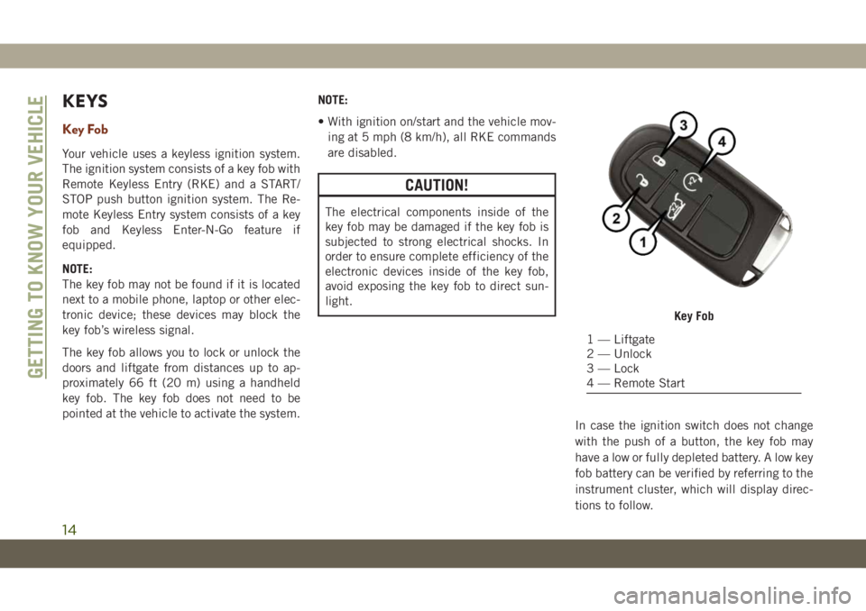
Key Fob
1 — Liftgate
2 — Unlock
3 — Lock
4 — Remote Start
GETTING TO KNOW YOUR VEHICLE
14
Page 18 of 378
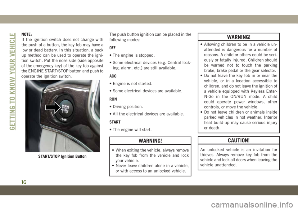
NOTE:
If the ignition switch does not change with
the push of a button, the key fob may have a
low or dead battery. In this situation, a back
up method can be used to operate the igni-
tion switch. Put the nose side (side opposite
of the emergency key) of the key fob against
the ENGINE START/STOP button and push to
operate the ignition switch.The push button ignition can be placed in the
following modes:
OFF
• The engine is stopped.
• Some electrical devices (e.g. Central lock-
ing, alarm, etc.) are still available.
ACC
• Engine is not started.
• Some electrical devices are available.
RUN
• Driving position.
• All the electrical devices are available.
START
• The engine will start.
WARNING!
• When exiting the vehicle, always remove
the key fob from the vehicle and lock
your vehicle.
• Never leave children alone in a vehicle,
or with access to an unlocked vehicle.
WARNING!
• Allowing children to be in a vehicle un-
attended is dangerous for a number of
reasons. A child or others could be seri-
ously or fatally injured. Children should
be warned not to touch the parking
brake, brake pedal or the gear selector.
• Do not leave the key fob in or near the
vehicle, or in a location accessible to
children, and do not leave the ignition of
a vehicle equipped with Keyless Enter-
N-Go in the ON/RUN mode. A child
could operate power windows, other
controls, or move the vehicle.
• Do not leave children or animals inside
parked vehicles in hot weather. Interior
heat build-up may cause serious injury
or death.
CAUTION!
An unlocked vehicle is an invitation for
thieves. Always remove key fob from the
vehicle and lock all doors when leaving the
vehicle unattended.
START/STOP Ignition Button
GETTING TO KNOW YOUR VEHICLE
16
Page 19 of 378
NOTE:
Refer to "Starting The Engine," in "Starting
And Operating" in the Owners Manual for
further information.
REMOTE STARTING
SYSTEM — IF EQUIPPED
• Push the remote start button on the key fob
twice within five seconds. Pushing the re-
mote start button a third time shuts the
engine off.
• With remote start, the engine will only run
for 15 minutes (time out) unless the igni-
tion is placed in the ON/RUN position.
• The vehicle must be manually started with
a push of the ignition START/STOP button
after two consecutive time outs.
WARNING!
• Do not start or run an engine in a closed
garage or confined area. Exhaust gas
contains Carbon Monoxide (CO) which
is odorless and colorless. Carbon Mon-
WARNING!
oxide is poisonous and can cause seri-
ous injury or death when inhaled.
• Keep key fobs away from children. Op-
eration of the Remote Start System,
windows, door locks or other controls
could cause serious injury or death.
How To Use Remote Start
• Push Remote Start button on the key fob
twice within five seconds. Pushing the Re-
mote Start button a third time shuts the
engine off.
• With remote start, the engine will only run
for 15 minutes (time out) unless the igni-
tion is placed in the ON/RUN position.
• The vehicle must be manually started with
a push of the ignition START/STOP button
after two consecutive time outs.
All of the following conditions must be met
before the engine will remote start:
• Gear Selector in PARK
• Doors closed
• Hood closed• Liftgate closed
• Hazard switch off
• Brake switch inactive (brake pedal not
pushed)
• Battery at an acceptable charge level
• System not disabled from previous remote
start event
• Vehicle alarm system indicator flashing
• Ignition in STOP/OFF position
• Fuel level meets minimum requirement
WARNING!
• Do not start or run an engine in a closed
garage or confined area. Exhaust gas
contains Carbon Monoxide (CO) which
is odorless and colorless. Carbon Mon-
oxide is poisonous and can cause seri-
ous injury or death when inhaled.
• Keep key fobs away from children. Op-
eration of the Remote Start System,
windows, door locks or other controls
could cause serious injury or death.
17
Page 22 of 378
zone (refer to "Keyless Enter-N-Go" in
“Doors” in Getting To Know Your Vehicle"
in your Owner’s Manual for further infor-
mation).
• Push the lock button on the key fob.
3. If any doors are open, close them.
NOTE:
• Once the security system is armed, it re-
mains in that state until you disarm it by
following either of the disarming proce-
dures described. If a power loss occurs
after arming the system, you must disarm
the system after restoring power to prevent
alarm activation.
• The ultrasonic intrusion sensor (motion de-
tector) actively monitors your vehicle every
time you arm the security system. If you
prefer, you can turn off the ultrasonic intru-
sion sensor when arming the security sys-
tem. To do so, push the lock button on the
key fob three times within 15 seconds of
arming the system (while the vehicle secu-
rity light is flashing rapidly).To Disarm The System
The vehicle security alarm can be disarmed
using any of the following methods:
• Push the unlock button on the key fob.
• Grasp the Passive Entry Unlock Door
Handle (refer to "Keyless Enter-N-Go" in
“Doors” in Getting To Know Your Vehicle" in
your Owner’s Manual for further informa-
tion).
• Cycle the vehicle ignition system out of the
OFF position.
– For vehicles equipped with Keyless
Enter-N-Go, push the Keyless Enter-
N-Go Start/Stop button (requires at
least one valid key fob in the vehicle).
– For vehicles not equipped with Keyless
Enter-N-Go, insert a valid key into the
ignition switch and turn the key to the
ON position.
NOTE:
• The driver's door key cylinder and the lift-
gate button on the key fob cannot arm or
disarm the vehicle security alarm.• The vehicle security alarm remains armed
during power liftgate entry. Pushing the
liftgate button will not disarm the vehicle
security alarm. If someone enters the ve-
hicle through the liftgate and opens any
door the alarm will sound.
• When the vehicle security alarm is armed,
the interior power door lock switches will
not unlock the doors.
• The ultrasonic intrusion sensor (motion de-
tector) actively monitors your vehicle every
time you arm the security system. If you
prefer, you can turn off the ultrasonic intru-
sion sensor when arming the security sys-
tem. To do so, push the lock button on the
key fob three times within 15 seconds of
arming the system (while the vehicle secu-
rity light is flashing rapidly).
The vehicle security alarm is designed to
protect your vehicle; however, you can create
conditions where the system will give you a
false alarm. If one of the previously described
arming sequences has occurred, the vehicle
security alarm will arm regardless of whether
GETTING TO KNOW YOUR VEHICLE
20
Page 57 of 378
will close fully and stop automatically. This is
called “Express Close”. During Express Close
operation, any other actuation of the switch
will stop the sunroof.
Manual
To close the sunroof, push and hold the
switch in the forward position. Any release of
the switch will stop the movement and the
sunroof will remain in a partially closed con-
dition until the sunroof switch is pushed
again.
Sunshade Operation
The sunshade can be opened manually. How-
ever, the sunshade will open automatically as
the sunroof opens.
NOTE:
The sunshade cannot be closed if the sunroof
is open.
Pinch Protect Feature
This feature will detect an obstruction in the
closing of the sunroof during the Express
Close operation. If an obstruction in the path
of the sunroof is detected, the sunroof will
automatically retract. Remove the obstruc-
tion if this occurs.
NOTE:
If three consecutive sunroof close attempts
result in Pinch Protect reversals, Pinch Pro-
tect will disable and the sunroof must be
closed in Manual Mode.
Venting Sunroof — Express
Push and release the Vent button within one
half second and the sunroof will open to the
vent position. This is called “Express Vent”
and it will occur regardless of sunroof posi-
tion. During Express Vent operation, any
movement of the switch will stop the sunroof.
Sunroof Maintenance
Use only a non-abrasive cleaner and a soft
cloth to clean the glass panel.
Relearn Procedure
For vehicles equipped with a single-pane
sunroof, there is a relearn procedure that
allows you to reset the sunroof when the
“Express Open” feature stops working. To
reset the sunroof, follow these steps:
1. Set the ignition to the ACC or ON/RUN
position.
2. Make sure that the sunroof is fully closed.
3. Push sunroof switch forward and hold.
The sunroof will close fully then move to
the Vent position after 10 seconds.
4. Release the sunroof switch, then push
forward and hold the switch again within
5 seconds to begin the relearn process.
The sunroof will complete one full cycle
and return to the Fully Closed position.
NOTE:
If the sunroof switch is released anytime
during the relearn cycle, the procedure
will need to be repeated starting from the
first step.
55
Page 68 of 378
INSTRUMENT CLUSTER
DISPLAY
Your vehicle will be equipped with an instru-
ment cluster display, which offers useful in-
formation to the driver. With the ignition in
the STOP/OFF mode, opening/closing of a
door will activate the display for viewing, and
display the total miles, or kilometers, in the
odometer. Your instrument cluster display is
designed to display important information
about your vehicle’s systems and features.
Using a driver interactive display located on
the instrument panel, your instrument clus-
ter display can show you how systems are
working and give you warnings when they are
not. The steering wheel mounted controls
allow you to scroll through the main menus
and submenus. You can access the specific
information you want and make selections
and adjustments.
Instrument Cluster Display Location And
Controls
The instrument cluster display is located in
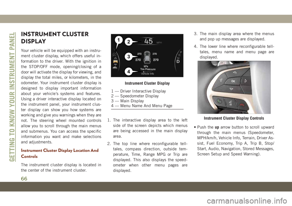
the center of the instrument cluster.1. The interactive display area to the left
side of the screen depicts which menus
are being accessed in the main display
area.
2. The top line where reconfigurable tell-
tales, compass direction, outside tem-
perature, Time, Range MPG or Trip are
displayed. This also displays the speed-
ometer when other menu pages are
displayed.3. The main display area where the menus
and pop up messages are displayed.
4. The lower line where reconfigurable tell-
tales, menu name and menu page are
displayed.
• Push theuparrow button to scroll upward
through the main menus (Speedometer,
MPH/km/h, Vehicle Info, Terrain, Driver As-
sist, Fuel Economy, Trip A, Trip B, Stop/
Start, Audio, Navigation, Stored Messages,
Screen Setup and Speed Warning).
Instrument Cluster Display
1 — Driver Interactive Display
2 — Speedometer Display
3 — Main Display
4 — Menu Name And Menu Page
Instrument Cluster Display Controls
GETTING TO KNOW YOUR INSTRUMENT PANEL
66
Page 69 of 378
• Push thedownarrow button to scroll down-
ward through the main menu and sub-
menus (Speedometer, MPH/km/h, Vehicle
Info, Terrain, Driver Assist, Fuel Economy,
Trip A, Trip B, Stop/Start, Audio, Naviga-
tion, Stored Messages, Screen Setup and
Speed Warning).
• Push therightarrow button to access the
information screens or submenu screens of
a main menu item.
• Push theleftarrow button to access the
information screens or submenu screens of
a main menu item.
• Push theOKbutton to access/select the
information screens or submenu screens of
a main menu item. Push and hold theOK
button for two seconds to reset displayed/
selected features that can be reset.
Oil Change Indicator System — If
Equipped
Your vehicle is equipped with an engine oil
change indicator system. The “Oil Change
Due” message will display in the instrument
cluster display for five seconds after a single
chime has sounded, to indicate the nextscheduled oil change interval. The engine oil
change indicator system is duty cycle based,
which means the engine oil change interval
may fluctuate, dependent upon your personal
driving style.
To have the oil changed, please refer to an
authorized dealer.
Instrument Cluster Display Selectable
Items
The instrument cluster display can be used to
view the main menu items for several fea-
tures. Use theupanddownarrow buttons to
scroll through the driver interactive display
menu options until the desired menu is
reached.
NOTE:
Depending on the vehicle’s options, feature
settings may vary.
Speedometer Trip
Accessibility — If
EquippedAudio
Vehicle Info Stored Messages
Driver Assist Screen Setup
Stop/Start — If
EquippedTerrain — If
Equipped
Performance Fea-
tures — If EquippedDiagnostics — If
Equipped
Fuel Economy Speed Warning
Refer to “Instrument Cluster Display” in
“Getting To Know Your Instrument Panel” in
the Owner’s Manual for further information.
Display Menu items
SRT Instrument Cluster Display Performance
Features
The instrument cluster display can be used to
program the following Performance Features.
67
Page 75 of 378
TRIP COMPUTER
Push and release the up or down arrow button
until the Trip A or Trip B icon is highlighted in
the instrument cluster display (Toggle left or
right to select Trip A or Trip B). Push and
release the OK button to display the Trip
information.
WARNING LIGHTS AND
MESSAGES
The warning/indicator lights will illuminate in
the instrument panel together with a dedi-
cated message and/or acoustic signal when
applicable. These indications are indicative
and precautionary and as such must not be
considered as exhaustive and/or alternative
to the information contained in the Owner’s
Manual, which you are advised to read care-
fully in all cases. Always refer to the informa-
tion in this chapter in the event of a failure
indication. All active telltales will display first
if applicable. The system check menu may
appear different based upon equipment op-
tions and current vehicle status. Some tell-
tales are optional and may not appear.
Red Warning Lights
— Air Bag Warning Light
This warning light will illuminate to indicate a
fault with the air bag, and will turn on for four
to eight seconds as a bulb check when the
ignition is placed in the ON/RUN or ACC/ON/
RUN position. This light will illuminate with a
single chime when a fault with the air bag has
been detected, it will stay on until the fault is
cleared. If the light is either not on during
startup, stays on, or turns on while driving,
have the system inspected at an authorized
dealer as soon as possible.
— Brake Warning Light
This warning light monitors various brake
functions, including brake fluid level and
parking brake application. If the brake light
turns on it may indicate that the parking
brake is applied, that the brake fluid level is
low, or that there is a problem with the
anti-lock brake system.
If the light remains on when the parking
brake has been disengaged, and the fluid
level is at the full mark on the master cylinder
reservoir, it indicates a possible brake hy-draulic system malfunction or that a problem
with the Brake Booster has been detected by
the Anti-Lock Brake System (ABS) / Elec-
tronic Stability Control (ESC) system. In this
case, the light will remain on until the condi-
tion has been corrected. If the problem is
related to the brake booster, the ABS pump
will run when applying the brake, and a brake
pedal pulsation may be felt during each stop.
The dual brake system provides a reserve
braking capacity in the event of a failure to a
portion of the hydraulic system. A leak in
either half of the dual brake system is indi-
cated by the Brake Warning Light, which will
turn on when the brake fluid level in the
master cylinder has dropped below a speci-
fied level.
The light will remain on until the cause is
corrected.
NOTE:
The light may flash momentarily during sharp
cornering maneuvers, which change fluid
level conditions. The vehicle should have
service performed, and the brake fluid level
checked.
73