tow JEEP GRAND CHEROKEE 2023 User Guide
[x] Cancel search | Manufacturer: JEEP, Model Year: 2023, Model line: GRAND CHEROKEE, Model: JEEP GRAND CHEROKEE 2023Pages: 424, PDF Size: 15.48 MB
Page 51 of 424
GETTING TO KNOW YOUR VEHICLE49
Third Row Head Restraints — If Equipped
The third row head restraints are not adjustable or
removable, but can be folded for improved visibility
when the vehicle is in REVERSE, and there are no
occupants in the seats.
Press the Headrest Fold button within the
Controls menu of the Uconnect system to
power fold the third row head restraints.
The head restraints will also automatically fold
when the seatbacks are folded forward using the
release handles on the backs of the seats from the
cargo area.
NOTE:
The head restraints must be raised manually
when occupying the third row.
Do not fold if there are passengers seated in the
third row seats.
MIRRORS
INSIDE REARVIEW MIRROR
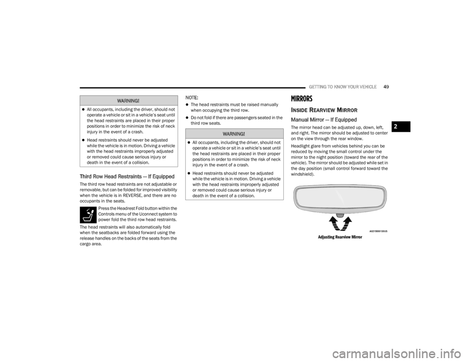
Manual Mirror — If Equipped
The mirror head can be adjusted up, down, left,
and right. The mirror should be adjusted to center
on the view through the rear window.
Headlight glare from vehicles behind you can be
reduced by moving the small control under the
mirror to the night position (toward the rear of the
vehicle). The mirror should be adjusted while set in
the day position (small control forward toward the
windshield).
Adjusting Rearview Mirror
WARNING!
All occupants, including the driver, should not
operate a vehicle or sit in a vehicle’s seat until
the head restraints are placed in their proper
positions in order to minimize the risk of neck
injury in the event of a crash.
Head restraints should never be adjusted
while the vehicle is in motion. Driving a vehicle
with the head restraints improperly adjusted
or removed could cause serious injury or
death in the event of a collision.
2
23_WL_OM_EN_USC_t.book Page 49
Page 52 of 424

50GETTING TO KNOW YOUR VEHICLE
Automatic Dimming Mirror — If Equipped
The mirror head can be adjusted up, down, left,
and right. The mirror should be adjusted to center
on the view through the rear window.
This mirror automatically adjusts for headlight
glare from vehicles behind you.
NOTE:The Automatic Dimming Mirror feature is disabled
when the vehicle is in REVERSE to improve the
driver’s view.
You can turn the feature on or off through the
Uconnect system Úpage 204.
Automatic Dimming Mirror
Digital Rearview Mirror — If Equipped
The Digital Rearview Mirror provides a high
definition, wide and unobstructed view of the road
behind while driving.
Position the mirror in the regular Automatic
Dimming Mirror mode, then activate the Digital
Rearview Mirror mode. To activate the Digital Rearview Mirror, pull the on/
off control lever on the bottom of the mirror
rearward toward the driver.
Digital Rearview Mirror
Push the menu button next to the on/off control/
toggle to access the following mirror options:
Brightness
Tilt
Use the menu button to scroll through the feature
options, and the left and right scroll buttons to
adjust the feature content (brightness or tilt)
higher/lower or up/down. When not in use, push the on/off forward toward
the windshield to return the mirror to the regular
Automatic Dimming Mirror.
NOTE:
The Digital Rearview Mirror is not as effective
during nighttime driving in low light applications
due to low ambient light levels. In the event that
it provides the user with less than expected
vision, the mirror can be reverted to a normal
reflective electrochromatic mirror by pushing
the control/toggle forward in the vehicle and
putting the mirror into Automatic Dimming
Mirror mode.
When the rear window washer is activated by
pushing the windshield wiper/washer lever
forward, the Rear Back Up and Digital Rearview
Mirror (if equipped) cameras are also washed.
For more information, see Ú
page 66.
ILLUMINATED VANITY MIRRORS
To access an illuminated vanity mirror, flip down
one of the visors.
Lift the cover to reveal the mirror. The light will turn
on automatically.
1 — On/Off Control/Toggle
2 — Menu Button
3 — Left Scroll Button
4 — Right Scroll Button
23_WL_OM_EN_USC_t.book Page 50
Page 53 of 424

GETTING TO KNOW YOUR VEHICLE51
Lift Cover On Vanity Mirror
Sun Visor Slide-On-Rod Feature —
If Equipped
The sun visor Slide-On-Rod feature allows for
additional flexibility in positioning the sun visor to
block out the sun.
1. Fold down the sun visor.
2. Unclip the visor from the center clip.
3. Pivot the sun visor toward the side window.
4. Extend the sun visor blade for additional sun blockage.
NOTE:The sun visor blade can also be extended while the
sun visor is against the windshield for additional
sun blockage through the front of the vehicle.
OUTSIDE MIRRORS
To receive maximum benefit, adjust the outside
mirror(s) to center on the adjacent lane of traffic
with a slight overlap of the view obtained on the
inside mirror.
Outside Mirrors Folding Feature
All outside mirrors are hinged and may be moved
either forward or rearward to resist damage. The
hinges have three detent positions:
Full forward position
Full rearward position
Normal position
Outside Mirrors With Turn Signal And
Approach Lighting — If Equipped
Driver and passenger outside mirrors with turn
signal and approach lighting contain four LEDs,
which are located in the upper outer corner of each
mirror.
Three of the LEDs are turn signal indicators, which
flash with the corresponding turn signal lights in
the front and rear of the vehicle. Turning on the
Hazard Warning flashers will also activate these
LEDs.
The fourth LED supplies illuminated entry lighting,
which turns on in both mirrors when you use the
key fob or open any door. This LED shines outward
to illuminate the front and rear door handles. It
also shines downward to illuminate the area in
front of the doors.
The illuminated entry lighting fades to off after
about 30 seconds or it will fade to off immediately
once the ignition is placed into the ON/RUN
position.
NOTE:The approach lighting will not function when the
gear selector is moved out of the PARK position.
WARNING!
Vehicles and other objects seen in an outside
convex mirror will look smaller and farther away
than they really are. Relying too much on side
convex mirrors could cause you to collide with
another vehicle or other object. Use your inside
mirror when judging the size or distance of a
vehicle seen in a side convex mirror.
2
23_WL_OM_EN_USC_t.book Page 51
Page 61 of 424
GETTING TO KNOW YOUR VEHICLE59
On some vehicles, the Daytime Running Lights
may deactivate, or reduce intensity, on one side
of the vehicle (when a turn signal is activated on
that side), or on both sides of the vehicle (when
the hazard warning lights are activated).
HIGH/LOW BEAM SWITCH
Push the multifunction lever toward the instrument
panel to switch the headlights to high beams.
Pulling the multifunction back toward the steering
wheel will turn the low beams back on, or shut the
high beams off.
AUTOMATIC HIGH BEAMS —
I
F EQUIPPED
The Automatic High Beam Headlight system
provides increased forward lighting at night by
automating high beam control through the use of a
digital camera mounted on the inside rearview
mirror. This camera detects vehicle specific light
and automatically switches from high beams to low
beams until the approaching vehicle is out of view.
NOTE:
The Automatic High Beam Headlight system can
be turned on or off by selecting or deselecting
“Auto Dim High Beams” within Uconnect
Settings Ú page 204.
The headlight switch must also be turned to the
AUTO position after Automatic High Beams is
enabled within Uconnect Settings for the
feature to activate.
Automatic High Beams will only activate when
the vehicle speed is above 22 mph (35 km/h).
Broken, muddy, or obstructed headlights and
taillights of vehicles in the field of view will
cause headlights to remain on longer (closer to
the vehicle). Also, dirt, film, and other obstruc -
tions on the windshield or camera lens will
cause the system to function improperly.
If the windshield or Automatic High Beam
Headlight Control mirror is replaced, the mirror
must be re-aimed to ensure proper performance.
See a local authorized dealer.
FLASH-TO-PASS
You can signal another vehicle with your headlights
by lightly pulling the multifunction lever toward you.
This will cause the high beam headlights to turn on,
and remain on, until the lever is released.
AUTOMATIC HEADLIGHTS
This system automatically turns the headlights on
or off according to ambient light levels. To turn the
system on, rotate the headlight switch
counterclockwise to the AUTO position. When the
system is on, the headlight time delay feature is
also on. This means the headlights will stay on for up to 90 seconds after you place the ignition into
the OFF position. The headlight time delay can be
programmed to 0/30/60/90 seconds within the
Uconnect system Ú
page 204.
To turn the automatic system off, move the
headlight switch out of the AUTO position.
NOTE:The engine must be running before the headlights
will come on in the automatic mode.
PARKING LIGHTS AND PANEL LIGHTS
To turn on the parking lights and instrument panel
lights, rotate the headlight switch clockwise. To
turn off the parking lights, rotate the headlight
switch back to the O (off) position.
NOTE:Vehicles sold in Canada are equipped with a head -
light switch with an AUTO and ON detent but
without an OFF detent. Headlights will be deacti -
vated when the headlight switch is placed in the
parking lights position. However, the Daytime
Running Lights (DRLs) will be activated along with
the front and rear marker lights. The DRLs may be
deactivated when the parking brake is engaged.
2
23_WL_OM_EN_USC_t.book Page 59
Page 66 of 424
64GETTING TO KNOW YOUR VEHICLE
WINDSHIELD WIPERS AND WASHERS
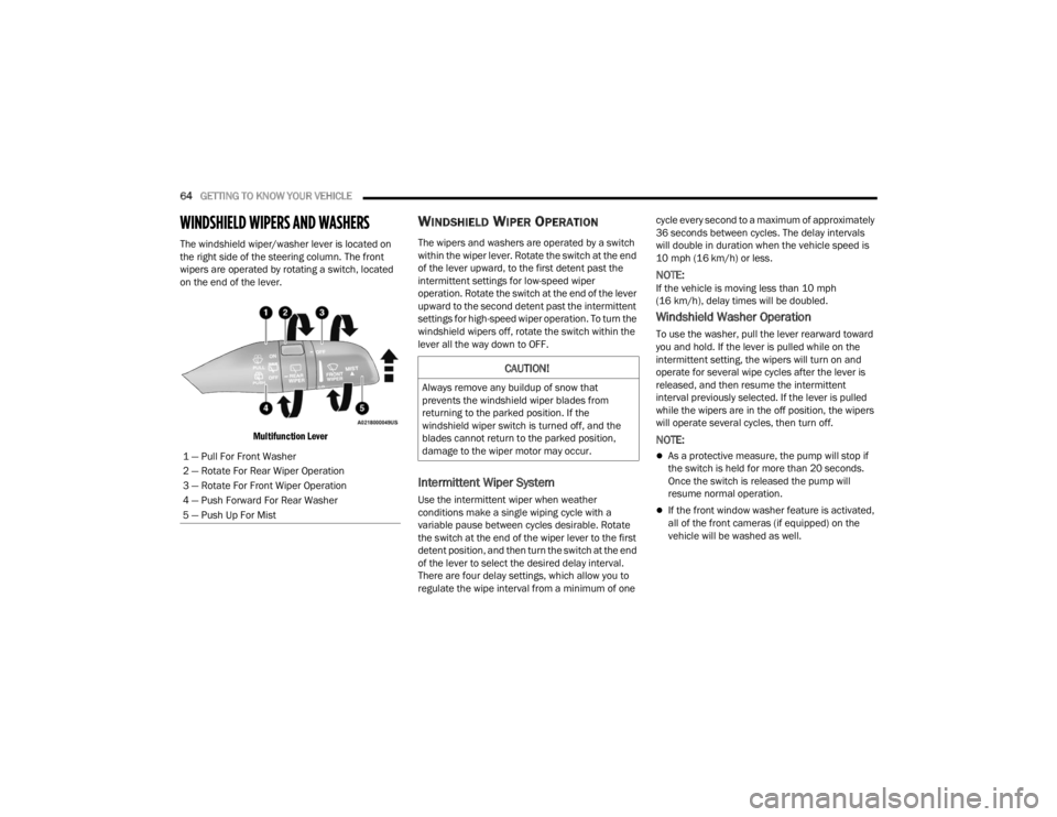
The windshield wiper/washer lever is located on
the right side of the steering column. The front
wipers are operated by rotating a switch, located
on the end of the lever.
Multifunction Lever
WINDSHIELD WIPER OPERATION
The wipers and washers are operated by a switch
within the wiper lever. Rotate the switch at the end
of the lever upward, to the first detent past the
intermittent settings for low-speed wiper
operation. Rotate the switch at the end of the lever
upward to the second detent past the intermittent
settings for high-speed wiper operation. To turn the
windshield wipers off, rotate the switch within the
lever all the way down to OFF.
Intermittent Wiper System
Use the intermittent wiper when weather
conditions make a single wiping cycle with a
variable pause between cycles desirable. Rotate
the switch at the end of the wiper lever to the first
detent position, and then turn the switch at the end
of the lever to select the desired delay interval.
There are four delay settings, which allow you to
regulate the wipe interval from a minimum of one cycle every second to a maximum of approximately
36 seconds between cycles. The delay intervals
will double in duration when the vehicle speed is
10 mph (16 km/h) or less.
NOTE:If the vehicle is moving less than 10 mph
(16 km/h), delay times will be doubled.
Windshield Washer Operation
To use the washer, pull the lever rearward toward
you and hold. If the lever is pulled while on the
intermittent setting, the wipers will turn on and
operate for several wipe cycles after the lever is
released, and then resume the intermittent
interval previously selected. If the lever is pulled
while the wipers are in the off position, the wipers
will operate several cycles, then turn off.
NOTE:
As a protective measure, the pump will stop if
the switch is held for more than 20 seconds.
Once the switch is released the pump will
resume normal operation.
If the front window washer feature is activated,
all of the front cameras (if equipped) on the
vehicle will be washed as well.
1 — Pull For Front Washer
2 — Rotate For Rear Wiper Operation
3 — Rotate For Front Wiper Operation
4 — Push Forward For Rear Washer
5 — Push Up For Mist
CAUTION!
Always remove any buildup of snow that
prevents the windshield wiper blades from
returning to the parked position. If the
windshield wiper switch is turned off, and the
blades cannot return to the parked position,
damage to the wiper motor may occur.
23_WL_OM_EN_USC_t.book Page 64
Page 70 of 424
68GETTING TO KNOW YOUR VEHICLE
Rear Climate Control Button
Press and release this button on the
climate control touchscreen to access
the rear climate controls. The Rear
Climate indicator will illuminate when the
rear climate controls are ON.
Driver And Passenger Temperature
Switches
These switches provide the driver and passenger
with independent temperature control. Lift the driver’s or passenger’s side
toggle switch on the faceplate upward, or
press and slide the temperature bar
towards the red arrow button on the
touchscreen for warmer temperature settings.
Depress the driver’s or passenger’s side
toggle switch on the faceplate downward,
or press and slide the temperature bar
towards the blue arrow button on the
touchscreen for cooler temperature settings.
SYNC Button
Press the SYNC button on the
touchscreen to toggle the SYNC feature
on/off. The SYNC indicator illuminates
when SYNC is on. SYNC is used to
synchronize the front passenger temperature and
rear passenger temperature, mode, and blower
settings with the driver temperature, mode, and
blower settings. Changing the front passenger
temperature or rear passenger temperature,
mode, and blower settings while in SYNC will
automatically exit this feature.
NOTE:
The SYNC setting is only available on the touch -
screen.
For vehicles equipped with the Four-Zone ATC
system, the rear climate control settings
(temperature, blower speed, and mode) will change to match the driver’s settings when the
vehicle is first started, without changing the
SYNC status.
When SYNC is not active, the rear passenger
climate control settings will need to be adjusted
manually to achieve desired comfort. See
Ú
page 69 or Ú page 71 for more information.
Blower Control
Blower Control is used to regulate the
amount of air forced through the Climate
Control system. There are several blower
speeds available.
Blower speed can be controlled by lifting blower
toggle on the instrument panel to increase blower
speed, or depress the toggle for lower blower
speed.
The speed can also be selected using the blower
control buttons on the touchscreen. Press the
blower bar area between the icons on the
touchscreen.
Mode Control
Select Mode by pressing one of the Mode
buttons on the touchscreen, or the
faceplate, to change the airflow
distribution mode. The airflow
distribution mode can be adjusted so air comes
from the instrument panel outlets, floor outlets,
defrost outlets and demist outlets.
CAUTION!
Failure to follow these cautions can cause
damage to the heating elements:
Use care when washing the inside of the rear
window. Do not use abrasive window cleaners
on the interior surface of the window. Use a
soft cloth and a mild washing solution, wiping
parallel to the heating elements. Labels can
be peeled off after soaking with warm water.
Do not use scrapers, sharp instruments, or
abrasive window cleaners on the interior
surface of the window.
Keep all objects a safe distance from the
window.
23_WL_OM_EN_USC_t.book Page 68
Page 91 of 424
GETTING TO KNOW YOUR VEHICLE89
ADJUSTABLE POWER LIFTGATE HEIGHT
The maximum height that the liftgate will open can
be adjusted and saved so that the liftgate will only
open to the desired height. To set a desired height,
proceed as follows:
1. Open the liftgate fully, then manually pull
down on the liftgate to the desired height.
2. Push and hold the liftgate close button, located on the left side trim panel inside the
cargo area, for three seconds. An audible
chime will be emitted to let you know the
height has been saved.
To set the saved height setting to a new setting,
proceed as follows:
1. Open the liftgate, then manually push the liftgate upward to its full open position.
2. Manually pull the liftgate down to the new desired height and hold the liftgate close
button for three seconds until the audible
chime is emitted. Power Liftgate Malfunction Procedure:
1. In the event of a power malfunction to the
liftgate, the liftgate can be released by
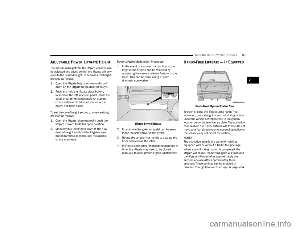
accessing the service release feature in the
latch. This can be done using a 3 mm
diameter screwdriver.
Liftgate Service Release
2. From inside the gate, an eyelet can be seen. Place the screwdriver in the eyelet.
3. Rotate the screwdriver handle to actuate the lever and release the latch.
4. If liftgate is left open for an extended period of time, the liftgate may need to be closed
manually to reset power liftgate functionality.
HANDS-FREE LIFTGATE — IF EQUIPPED
Hands-Free Liftgate Activation Zone
To open or close the liftgate using hands-free
activation, use a straight in and out kicking motion
under the vehicle activation zone in the general
location below the rear license plate. The activation
zone is about 1.8 ft (0.5 m) from side to side. Do not
move your foot sideways or in a sweeping motion or
the sensors may not detect the motion.
NOTE:The activation zone is the same for vehicles
equipped with or without a trailer tow package.
When a valid kicking motion is completed, the
liftgate will chime, the hazard lights will flash and
the liftgate will open after approximately one
second, or close after approximately three
seconds. These settings can be enabled or
disabled through Uconnect Settings Ú page 204.
2
23_WL_OM_EN_USC_t.book Page 89
Page 98 of 424
96GETTING TO KNOW YOUR INSTRUMENT PANEL
Use this QR code to access your
digital experience.
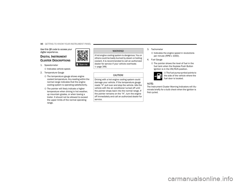
DIGITAL INSTRUMENT
C
LUSTER DESCRIPTIONS
1. Speedometer
Indicates vehicle speed.
2. Temperature Gauge
The temperature gauge shows engine
coolant temperature. Any reading within the
normal range indicates that the engine
cooling system is operating satisfactorily.
The pointer will likely indicate a higher
temperature when driving in hot weather,
up mountain grades, or when towing a
trailer. It should not be allowed to exceed
the upper limits of the normal operating
range. 3. Tachometer
Indicates the engine speed in revolutions
per minute (RPM x 1000).
4. Fuel Gauge
The pointer shows the level of fuel in the
fuel tank when the Keyless Push Button
Ignition is in the ON/RUN position.
The fuel pump symbol points to
the side of the vehicle where the
fuel door is located.
NOTE:The Instrument Cluster Warning Indicators will illu -
minate briefly for a bulb check when the ignition is
first cycled.
WARNING!
A hot engine cooling system is dangerous. You or
others could be badly burned by steam or boiling
coolant. It is recommended to call an authorized
dealer for service if your vehicle overheats
Ú page 346.
CAUTION!
Driving with a hot engine cooling system could
damage your vehicle. If the temperature gauge
reads “H” pull over and stop the vehicle. Idle the
vehicle with the air conditioner turned off until
the pointer drops back into the normal range. If
the pointer remains on the “H”, turn the engine
off immediately and call an authorized dealer for
service.
23_WL_OM_EN_USC_t.book Page 96
Page 100 of 424
98GETTING TO KNOW YOUR INSTRUMENT PANEL
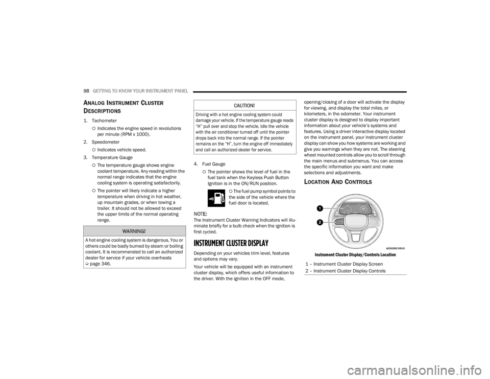
ANALOG INSTRUMENT CLUSTER
D
ESCRIPTIONS
1. Tachometer
Indicates the engine speed in revolutions
per minute (RPM x 1000).
2. Speedometer
Indicates vehicle speed.
3. Temperature Gauge
The temperature gauge shows engine
coolant temperature. Any reading within the
normal range indicates that the engine
cooling system is operating satisfactorily.
The pointer will likely indicate a higher
temperature when driving in hot weather,
up mountain grades, or when towing a
trailer. It should not be allowed to exceed
the upper limits of the normal operating
range. 4. Fuel Gauge
The pointer shows the level of fuel in the
fuel tank when the Keyless Push Button
Ignition is in the ON/RUN position.
The fuel pump symbol points to
the side of the vehicle where the
fuel door is located.
NOTE:The Instrument Cluster Warning Indicators will illu -
minate briefly for a bulb check when the ignition is
first cycled.
INSTRUMENT CLUSTER DISPLAY
Depending on your vehicles trim level, features
and options may vary.
Your vehicle will be equipped with an instrument
cluster display, which offers useful information to
the driver. With the ignition in the OFF mode, opening/closing of a door will activate the display
for viewing, and display the total miles, or
kilometers, in the odometer. Your instrument
cluster display is designed to display important
information about your vehicle’s systems and
features. Using a driver interactive display located
on the instrument panel, your instrument cluster
display can show you how systems are working and
give you warnings when they are not. The steering
wheel mounted controls allow you to scroll through
the main menus and submenus. You can access
the specific information you want and make
selections and adjustments.
LOCATION AND CONTROLS
Instrument Cluster Display/Controls Location
WARNING!
A hot engine cooling system is dangerous. You or
others could be badly burned by steam or boiling
coolant. It is recommended to call an authorized
dealer for service if your vehicle overheats
Ú
page 346.
CAUTION!
Driving with a hot engine cooling system could
damage your vehicle. If the temperature gauge reads
“H” pull over and stop the vehicle. Idle the vehicle
with the air conditioner turned off until the pointer
drops back into the normal range. If the pointer
remains on the “H”, turn the engine off immediately
and call an authorized dealer for service.
1 – Instrument Cluster Display Screen
2 – Instrument Cluster Display Controls
23_WL_OM_EN_USC_t.book Page 98
Page 109 of 424
GETTING TO KNOW YOUR INSTRUMENT PANEL107
When load reduction is activated, the message
“Battery Saver On” or “Battery Saver Mode” will
appear in the instrument cluster.
These messages indicate the vehicle battery has a
low state of charge and continues to lose electrical
charge at a rate that the charging system cannot
sustain.
NOTE:
The charging system is independent from load
reduction. The charging system performs a diag -
nostic on the charging system continuously.
If the Battery Charge Warning Light is on it may
indicate a problem with the charging system
Ú page 109.
The electrical loads that may be switched off (if
equipped), and vehicle functions which can be
affected by load reduction:
Heated Seat/Vented Seats/Heated Wheel
Rear Defroster And Heated Mirrors
HVAC System
115 Volt AC Power Inverter System
Audio and Telematics System Loss of the battery charge may indicate one or
more of the following conditions:
The charging system cannot deliver enough
electrical power to the vehicle system because
the electrical loads are larger than the capability
of the charging system. The charging system is
still functioning properly.
Turning on all possible vehicle electrical loads
(e.g. HVAC to max settings, exterior and interior
lights, overloaded power outlets +12 Volt, 115
Volt AC, USB ports) during certain driving condi
-
tions (city driving, towing, frequent stopping,
etc.).
Installing options like additional lights, upfitter
electrical accessories, audio systems, alarms
and similar devices.
Unusual driving cycles (short trips separated by
long parking periods).
The vehicle was parked for an extended period
of time (weeks, months).
The battery was recently replaced and was not
charged completely.
The battery was discharged by an electrical load
left on when the vehicle was parked.
The battery was used for an extended period
with the engine not running to supply radio,
lights, chargers, +12 Volt portable appliances
like vacuum cleaners, game consoles and
similar devices. What to do when an electrical load reduction
action message is present (“Battery Saver On” or
“Battery Saver Mode”)
During a trip:
Reduce power to unnecessary loads if possible:
Turn off redundant lights (interior or exte
-
rior)
Check what may be plugged in to power
outlets +12 Volt, 115 Volt AC, USB ports
Check HVAC settings (blower, temperature)
Check the audio settings (volume)
After a trip:
Check if any aftermarket equipment was
installed (additional lights, upfitter electrical
accessories, audio systems, alarms) and review
specifications if any (load and Ignition Off Draw
currents).
Evaluate the latest driving cycles (distance,
driving time and parking time).
The vehicle should have service performed if
the message is still present during consecutive
trips, and if the evaluation and driving pattern of
the vehicle did not help to identify the cause.
3
23_WL_OM_EN_USC_t.book Page 107