sensor JEEP GRAND CHEROKEE 2023 Owner's Manual
[x] Cancel search | Manufacturer: JEEP, Model Year: 2023, Model line: GRAND CHEROKEE, Model: JEEP GRAND CHEROKEE 2023Pages: 424, PDF Size: 15.48 MB
Page 172 of 424
170STARTING AND OPERATING
When the system instructs the driver to remove
their hands from the steering wheel, the driver
should check their surroundings and begin to
back up slowly.
The ParkSense Active Park Assist system will
allow a maximum of eight shifts between DRIVE
and REVERSE. If the maneuver cannot be
completed within eight shifts, the system will
cancel and the instrument cluster display will
instruct the driver to complete the maneuver
manually.
The system will cancel the maneuver if the
vehicle speed exceeds 5 mph (7 km/h) during
active steering guidance into the parking space.
The system will provide a warning to the driver
at 3 mph (5 km/h) that tells them to slow down.
The driver is then responsible for completing the
maneuver if the system is canceled.
If the system is canceled during the maneuver
for any reason, the driver must take control of
the vehicle.EXITING THE PARKING SPACE
NOTE:The function does not work for exiting a perpen -
dicular parking space, but only exiting parallel
parking spaces.
Activation
To activate this function, push the Active
ParkSense switch once. After selection, the system
activates and warns the driver on the instrument
cluster display about the operations that have to
be carried out to perform the maneuver correctly.
WARNING!
Drivers must be careful when performing
parallel or perpendicular parking maneuvers
even when using the ParkSense Active Park
Assist system. Always check carefully behind
and in front of your vehicle, look behind and in
front of you, and be sure to check for pedes -
trians, animals, other vehicles, obstructions,
and blind spots before backing up and moving
forward. You are responsible for safety and
must continue to pay attention to your
surroundings. Failure to do so can result in
serious injury or death.
Before using the ParkSense Active Park Assist
system, it is strongly recommended that the
ball mount and hitch ball assembly be discon -
nected from the vehicle when the vehicle is
not used for towing. Failure to do so can result
in injury or damage to vehicles or obstacles
because the hitch ball will be much closer to
the obstacle than the rear fascia when the
vehicle sounds the continuous tone. Also, the
sensors could detect the ball mount and hitch
ball assembly, depending on its size and
shape, giving a false indication that an
obstacle is behind the vehicle.
CAUTION!
The ParkSense Active Park Assist system is
only a parking aid and it is unable to recognize
every obstacle, including small obstacles.
Parking curbs might be temporarily detected
or not detected at all. Obstacles located above
or below the sensors will not be detected
when they are in close proximity.
The vehicle must be driven slowly when using
the ParkSense Active Park Assist system in
order to be able to stop in time when an
obstacle is detected. It is recommended that
the driver looks over his/her shoulder when
using the ParkSense Active Park Assist
system.
23_WL_OM_EN_USC_t.book Page 170
Page 173 of 424
STARTING AND OPERATING171
Selection Of The Maneuver Side
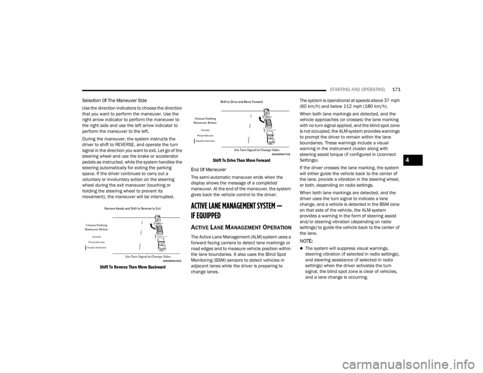
Use the direction indicators to choose the direction
that you want to perform the maneuver. Use the
right arrow indicator to perform the maneuver to
the right side and use the left arrow indicator to
perform the maneuver to the left.
During the maneuver, the system instructs the
driver to shift to REVERSE, and operate the turn
signal in the direction you want to exit. Let go of the
steering wheel and use the brake or accelerator
pedals as instructed, while the system handles the
steering automatically for exiting the parking
space. If the driver continues to carry out a
voluntary or involuntary action on the steering
wheel during the exit maneuver (touching or
holding the steering wheel to prevent its
movement), the maneuver will be interrupted.
Shift To Reverse Then Move Backward Shift To Drive Then Move Forward
End Of Maneuver
The semi-automatic maneuver ends when the
display shows the message of a completed
maneuver. At the end of the maneuver, the system
gives back the vehicle control to the driver.
ACTIVE LANE MANAGEMENT SYSTEM —
IF EQUIPPED
ACTIVE LANE MANAGEMENT OPERATION
The Active Lane Management (ALM) system uses a
forward facing camera to detect lane markings or
road edges and to measure vehicle position within
the lane boundaries. It also uses the Blind Spot
Monitoring (BSM) sensors to detect vehicles in
adjacent lanes while the driver is preparing to
change lanes. The system is operational at speeds above 37 mph
(60 km/h) and below 112 mph (180 km/h).
When both lane markings are detected, and the
vehicle approaches (or crosses) the lane marking
with no turn signal applied, and the blind spot zone
is not occupied, the ALM system provides warnings
to prompt the driver to remain within the lane
boundaries. These warnings include a visual
warning in the instrument cluster along with
steering assist torque (if configured in Uconnect
Settings).
If the driver crosses the lane marking, the system
will either guide the vehicle back to the center of
the lane, provide a vibration in the steering wheel,
or both, depending on radio settings.
When both lane markings are detected, and the
driver uses the turn signal to indicate a lane
change, and a vehicle is detected in the BSM zone
on that side of the vehicle, the ALM system
provides a warning in the form of steering assist
and/or steering vibration (depending on radio
settings) to guide the vehicle back to the center of
the lane.NOTE:
The system will suppress visual warnings,
steering vibration (if selected in radio settings),
and steering assistance (if selected in radio
settings) when the driver activates the turn
signal, the blind spot zone is clear of vehicles,
and a lane change is occurring.
4
23_WL_OM_EN_USC_t.book Page 171
Page 182 of 424
180STARTING AND OPERATING
SERVICE THE NIGHT VISION SYSTEM
When service conditions are present, the following
fault messages may appear in the instrument
cluster display when the vehicle is placed in the ON
position.
If "Night Vision Unavailable Sensor Blocked"
appears in the instrument cluster display, make
sure the camera is clear of snow, ice, mud, dirt or
other debris. The camera is located in the upper
fascia/bumper, inside the driver side grille slot.
Clean the camera using a soft wet cloth or by
pressing the Clean Camera button in the Uconnect
system. If the message continues to appear after
cycling the ignition, see an authorized dealer.
If “Night Vision Temporarily Unavailable” or “Night
Vision Unavailable Service Required" appears in
the instrument cluster display after cycling the
ignition, see an authorized dealer.
The camera must be properly aligned to work
correctly. If the camera needs adjustment, see an
authorized dealer. Do not attempt to adjust the
camera yourself.
NOTE:Alignment and performance of the Night Vision
may be affected by aftermarket modifications.
Mopar® parts should be used to get the optimal
performance of this system.
NIGHT VISION SYSTEM LIMITATIONS
The Night Vision display is deactivated under the
following conditions:
Vehicle is shifted into REVERSE
The ignition is not in the ON/RUN position
The headlights are off and the vehicle speed is
greater than 8 mph (13 km/h)
The Night Vision display warnings are suppressed
under the following conditions:
Daylight hours
Temperatures above 86°F (30°C)
The system may not be fully functional in the
following situations:
On steep hills
On tight curves of the road
If the camera/sensor is damaged or blocked by
dirt, snow, ice, or other debris
In poor visibility conditions such as heavy fog,
rain, snow, or other weather conditions
If the vehicle has been modified with after -
market parts and/or accessories
NOTE:If any of these conditions are present, the system
does not need service.
WARNING!
Night Vision can only detect pedestrians and
animals located within the range of the
infrared camera.
Night Vision may not detect pedestrians or
animals and highlight them if:
They are not in an upright position, for
example if they are sitting or lying down, or
if the pedestrian is riding a bicycle
The figure in the display appears incom -
plete, for example because the pedes -
trian or animal is partially behind a vehicle
The pedestrian/animal is not directly
ahead in the coverage area
The pedestrian/animal is part of a group
The pedestrian is wearing certain types of
clothing
The pedestrian/animal is moving too
quickly through the field of view
The sensor is blocked by dirt, rain, snow,
or ice
23_WL_OM_EN_USC_t.book Page 180
Page 253 of 424
SAFETY251
Electronic Brake Force Distribution (EBD)
EBD manages the distribution of the braking
torque between the front and rear axles by limiting
braking pressure to the rear axle. This is done to
prevent overslip of the rear wheels to avoid vehicle
instability, and to prevent the rear axle from
entering ABS before the front axle.
Electronic Roll Mitigation (ERM)
ERM anticipates the potential for wheel lift by
monitoring the driver’s steering wheel input and
the speed of the vehicle. When ERM determines
that the rate of change of the steering wheel angle
and vehicle’s speed are sufficient to potentially
cause wheel lift, it then applies the appropriate
brake and may also reduce engine power to lessen
the chance that wheel lift will occur. ERM can only
reduce the chance of wheel lift occurring during
severe or evasive driving maneuvers; it cannot
prevent wheel lift due to other factors, such as
road conditions, leaving the roadway, or striking
objects or other vehicles.
NOTE:ERM is disabled any time the ESC is in “Full Off”
mode (if equipped). See Ú page 251 for a
complete explanation of the available ESC modes.
Electronic Stability Control (ESC)
ESC enhances directional control and stability of
the vehicle under various driving conditions. ESC
corrects for oversteering or understeering of the
vehicle by applying the brake of the appropriate
wheel(s) to assist in counteracting the following
conditions. Engine power may also be reduced to
help the vehicle maintain the desired path.
Oversteer — when the vehicle is turning more
than appropriate for the steering wheel position.
Understeer — when the vehicle is turning less
than appropriate for the steering wheel position.
ESC uses sensors in the vehicle to determine the
vehicle path intended by the driver and compares
it to the actual path of the vehicle. When the actual
path does not match the intended path, ESC
applies the brake of the appropriate wheel to
assist in counteracting the oversteer or understeer
condition.
The ESC Activation/Malfunction Indicator Light
located in the instrument cluster will start to flash
as soon as the ESC system becomes active. The
ESC Activation/Malfunction Indicator Light also
flashes when the Traction Control System (TCS) is
active. If the ESC Activation/Malfunction Indicator
Light begins to flash during acceleration, ease up
on the accelerator and apply as little throttle as
possible. Be sure to adapt your speed and driving
to the prevailing road conditions.
WARNING!
Many factors, such as vehicle loading, road
conditions and driving conditions, influence the
chance that wheel lift or rollover may occur. ERM
cannot prevent all wheel lift or rollovers,
especially those that involve leaving the roadway
or striking objects or other vehicles. The
capabilities of an ERM-equipped vehicle must
never be exploited in a reckless or dangerous
manner which could jeopardize the user's safety
or the safety of others.
6
23_WL_OM_EN_USC_t.book Page 251
Page 259 of 424
SAFETY257
Feedback To The Driver:
The instrument cluster has an SSC icon and the
SSC switch has an LED which offer feedback to the
driver about the state SSC is in.
The cluster icon and switch light will illuminate
and remain on solid when SSC is enabled or
activated. This is the normal operating condition
for SSC.
The cluster icon and switch light will flash for
several seconds then extinguish when the driver
pushes the SSC switch but enable conditions
are not met.
The cluster icon and switch light will flash for
several seconds then extinguish when SSC
disables due to excess speed.
The cluster icon and switch light will flash then
extinguish when SSC deactivates due to over -
heated brakes.
Traction Control System (TCS)
The TCS monitors the amount of wheel spin of
each of the driven wheels. If wheel spin is
detected, the TCS may apply brake pressure to the
spinning wheel(s) and/or reduce engine power to
provide enhanced acceleration and stability. A
feature of the TCS, Brake Limited Differential (BLD)
functions similarly to a limited slip differential and
controls the wheel spin across a driven axle. If one
wheel on a driven axle is spinning faster than the
other, the system will apply the brake of the
spinning wheel. This will allow more engine power
to be applied to the wheel that is not spinning. BLD
may remain enabled even if TCS and Electronic
Stability Control (ESC) are in reduced modes.
Trailer Sway Control (TSC)
TSC uses sensors in the vehicle to recognize an
excessively swaying trailer and will take the
appropriate actions to attempt to stop the sway.
TSC will become active automatically once an
excessively swaying trailer is recognized.
NOTE:TSC cannot stop all trailers from swaying. Always
use caution when towing a trailer and follow the
trailer tongue weight recommendations
Ú page 185.
When TSC is functioning, the ESC Activation/
Malfunction Indicator Light will flash, the engine
power may be reduced and you may feel the
brakes being applied to individual wheels to
attempt to stop the trailer from swaying. TSC is
disabled when the ESC system is in the “Partial
Off” mode.
WARNING!
SSC is only intended to assist the driver in
controlling vehicle speed when driving in off
road conditions. The driver must remain
attentive to the driving conditions and is
responsible for maintaining a safe vehicle
speed.
WARNING!
If TSC activates while driving, slow the vehicle
down, stop at the nearest safe location, and
adjust the trailer load to eliminate trailer sway.6
23_WL_OM_EN_USC_t.book Page 257
Page 260 of 424
258SAFETY
AUXILIARY DRIVING SYSTEMS
BLIND SPOT MONITORING (BSM)
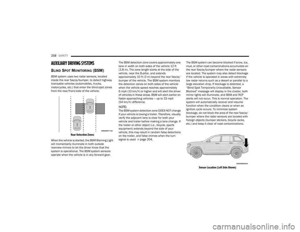
BSM system uses two radar sensors, located
inside the rear fascia/bumper, to detect highway
licensable vehicles (automobiles, trucks,
motorcycles, etc.) that enter the blind spot zones
from the rear/front/side of the vehicle.
Rear Detection Zones
When the vehicle is started, the BSM Warning Light
will momentarily illuminate in both outside
rearview mirrors to let the driver know that the
system is operational. The BSM system sensors
operate when the vehicle is in any forward gear. The BSM detection zone covers approximately one
lane in width on both sides of the vehicle 12 ft
(3.8 m). The zone length starts at the side of the
vehicle, near the B-pillar, and extends
approximately 10 ft (3 m) beyond the rear fascia/
bumper of the vehicle. The BSM system monitors
the detection zones on both sides of the vehicle
when the vehicle speed reaches approximately
6 mph (10 km/h) or higher and will alert the driver
of vehicles in these areas. BSM will alert earlier on
faster-approaching vehicles — up to 33 mph
(54 km/h) difference.
NOTE:The BSM system detection zone DOES NOT change
if your vehicle is towing a trailer. Therefore, visually
verify the adjacent lane is clear for both your
vehicle and trailer before making a lane change. If
the trailer or other object (i.e., bicycle, sports
equipment) extends beyond the side of your
vehicle, this may result in random false detections
on the trailer, and false chimes when the turn
signal is used Ú
page 204. The BSM system can become blocked if snow, ice,
mud, or other road contaminations accumulate on
the rear fascia/bumper where the radar sensors
are located. The system may also detect blockage
if the vehicle is operated in areas with extremely
low radar returns such as a desert or parallel to a
large elevation drop. If blockage is detected, a
“Blind Spot Temporarily Unavailable, Sensor
Blocked” message will display in the cluster, both
mirror lights will illuminate, and BSM and RCP
alerts will not occur. This is normal operation. The
system will automatically recover and resume
function when the condition clears or when an
ignition cycle occurs. To minimize system
blockage, do not block the area of the rear fascia/
bumper where the radar sensors are located with
foreign objects (bumper stickers, bicycle racks,
etc.) and keep it clear of road contaminations.
Sensor Location (Left Side Shown)
23_WL_OM_EN_USC_t.book Page 258
Page 262 of 424
260SAFETY
The BSM system is designed not to issue an alert on
stationary objects such as guardrails, posts, walls,
foliage, berms, etc. However, occasionally the
system may alert on such objects. This is normal
operation and your vehicle does not require service.
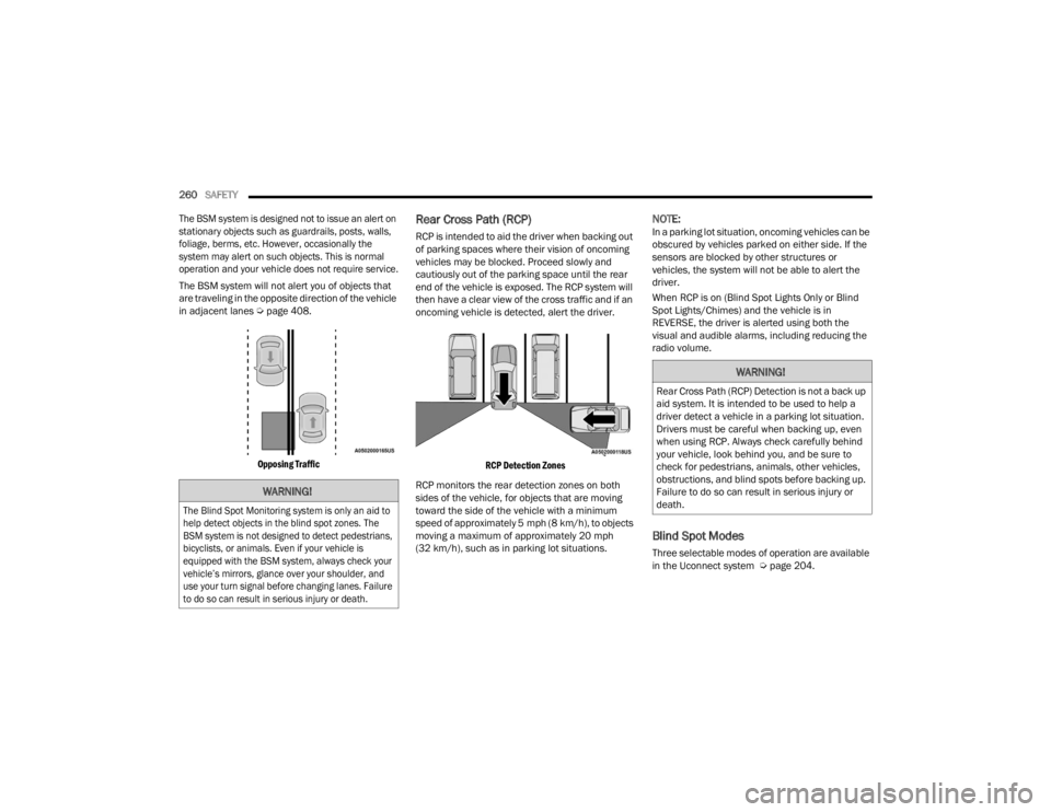
The BSM system will not alert you of objects that
are traveling in the opposite direction of the vehicle
in adjacent lanes Ú page 408.
Opposing Traffic
Rear Cross Path (RCP)
RCP is intended to aid the driver when backing out
of parking spaces where their vision of oncoming
vehicles may be blocked. Proceed slowly and
cautiously out of the parking space until the rear
end of the vehicle is exposed. The RCP system will
then have a clear view of the cross traffic and if an
oncoming vehicle is detected, alert the driver.
RCP Detection Zones
RCP monitors the rear detection zones on both
sides of the vehicle, for objects that are moving
toward the side of the vehicle with a minimum
speed of approximately 5 mph (8 km/h), to objects
moving a maximum of approximately 20 mph
(32 km/h), such as in parking lot situations.
NOTE:In a parking lot situation, oncoming vehicles can be
obscured by vehicles parked on either side. If the
sensors are blocked by other structures or
vehicles, the system will not be able to alert the
driver.
When RCP is on (Blind Spot Lights Only or Blind
Spot Lights/Chimes) and the vehicle is in
REVERSE, the driver is alerted using both the
visual and audible alarms, including reducing the
radio volume.
Blind Spot Modes
Three selectable modes of operation are available
in the Uconnect system Ú page 204.
WARNING!
The Blind Spot Monitoring system is only an aid to
help detect objects in the blind spot zones. The
BSM system is not designed to detect pedestrians,
bicyclists, or animals. Even if your vehicle is
equipped with the BSM system, always check your
vehicle’s mirrors, glance over your shoulder, and
use your turn signal before changing lanes. Failure
to do so can result in serious injury or death.
WARNING!
Rear Cross Path (RCP) Detection is not a back up
aid system. It is intended to be used to help a
driver detect a vehicle in a parking lot situation.
Drivers must be careful when backing up, even
when using RCP. Always check carefully behind
your vehicle, look behind you, and be sure to
check for pedestrians, animals, other vehicles,
obstructions, and blind spots before backing up.
Failure to do so can result in serious injury or
death.
23_WL_OM_EN_USC_t.book Page 260
Page 263 of 424
SAFETY261
Blind Spot Alert Lights Only
When operating in Blind Spot Alert mode, the BSM
system will provide a visual alert in the appropriate
side view mirror based on a detected object.
However, when the system is operating in Rear
Cross Path (RCP) mode, the system will respond
with both visual and audible alerts when a
detected object is present. Whenever an audible
alert is requested, the radio is muted.
Blind Spot Alert Lights/Chime
When operating in Blind Spot Alert Lights/Chime
mode, the BSM system will provide a visual alert in
the appropriate side view mirror based on a
detected object. If the turn signal is then activated,
and it corresponds to an alert present on that side
of the vehicle, an audible chime will also be
sounded. Whenever a turn signal and detected
object are present on the same side at the same
time, both the visual and audible alerts will be
issued. In addition to the audible alert the radio (if
on) will also be muted.
NOTE:Whenever an audible alert is requested by the
BSM system, the radio is also muted. When the system is in RCP, the system shall
respond with both visual and audible alerts when a
detected object is present. Whenever an audible
alert is requested, the radio is also muted. Turn/
hazard signal status is ignored; the RCP state
always requests the chime.
Blind Spot Alert Off
When the BSM system is turned off, there will be
no visual or audible alerts from either the BSM or
RCP systems.
NOTE:The BSM system will store the current operating
mode when the vehicle is shut off. Each time the
vehicle is started, the previously stored mode will
be recalled and used.
FORWARD COLLISION WARNING (FCW)
W
ITH MITIGATION
The FCW with Mitigation system provides the driver
with audible warnings, visual warnings (within the
instrument cluster display), and may apply a
limited braking to warn the driver when it detects a
potential frontal collision. The warnings and limited
braking are intended to provide the driver with
enough time to react, avoid or mitigate the
potential collision.
NOTE:If either FCW or Pedestrian Emergency Braking
(PEB) is turned off, the FCW OFF Indicator Light will
illuminate. The FCW OFF Indicator Light will only
shut off if both features are turned on and active
braking is enabled.
NOTE:FCW monitors the information from the forward
looking sensors as well as the Electronic Brake
Controller (EBC), to calculate the probability of a
forward collision. When the system determines
that a forward collision is probable, the driver will
be provided with audible and visual warnings and
may provide a brake jerk warning. If the driver does
not take action based upon these progressive
warnings, then the system will provide a limited
level of active braking to help slow the vehicle and
mitigate the potential forward collision. If the driver
reacts to the warnings by braking and the system
determines that the driver intends to avoid the
collision by braking but has not applied sufficient
brake force, the system will compensate and
provide additional brake force as required.
6
23_WL_OM_EN_USC_t.book Page 261
Page 266 of 424
264SAFETY
Turning PEB On Or Off
NOTE:The default status of PEB is “On.” This allows the
system to warn you of a possible frontal collision
with the pedestrian.
The PEB button is located in the Uconnect display
in the Control settings Ú page 204.
To turn the PEB system off, push the Pedestrian
Emergency Braking button.
To turn the PEB system back on, push the Warning
Active Braking button.
Changing the PEB status to “Off” deactivates the
system, so no warning or active braking will be
available in case of a possible frontal collision with
the pedestrian/cyclist.
NOTE:The PEB system will retain the last setting selected
by the driver after ignition shut down. The system
will not reset to the default setting when the
vehicle is restarted.
Intersection Collision Assist (ICA) —
If Equipped
ICA uses three front radar sensors located in the
front fascia/bumper, to detect oncoming vehicles
from the front or side when driving through an
intersection. When the system determines that a
collision is probable when turning across
oncoming traffic, the system will attempt to
mitigate a possible collision by decelerating the
vehicle. When the system determines that a
collision with a crossing vehicle is probable, the
system may apply additional braking to
supplement the driver braking input to attempt to
mitigate a possible collision. The system will also
provide audible warnings and visual warnings
(shown in the instrument cluster). If the driver
determines acceleration is needed to avoid a
collision, when the accelerator is pressed ICA will
cancel.
TIRE PRESSURE MONITORING SYSTEM
(TPMS)
The TPMS will warn the driver of a low tire pressure
based on the vehicle recommended cold tire
pressure Ú page 408.
The tire pressure will vary with temperature by about
1 psi (7 kPa) for every 12°F (6.5°C). This means that
when the outside temperature decreases, the tire
pressure will decrease. Tire pressure should always
be set based on cold inflation tire pressure. This is
defined as the tire pressure after the vehicle has not
been driven for at least three hours, or driven less
than 1 mile (1.6 km) after a three-hour period. The
tire pressure will also increase as the vehicle is
driven — this is normal and there should be no
adjustment for this increased pressure.
For information on how to properly inflate the
vehicle’s tires, see Ú
page 374.
The TPMS will warn the driver of a low tire pressure
if the tire pressure falls below the low pressure
warning threshold for any reason, including low
temperature effects, or natural pressure loss
through the tire.
The TPMS will continue to warn the driver of low
tire pressure as long as the condition exists, and
will not turn off until the tire pressure is at or above
recommended cold tire pressure. Once the low tire
pressure warning has been illuminated, the tire
pressure must be increased to the recommended
cold tire pressure in order for the TPMS Warning
Light to be turned off.
WARNING!
Pedestrian Emergency Braking (PEB) is not
intended to avoid a collision on its own, nor can
PEB detect every type of potential collision with
a pedestrian. The driver has the responsibility to
avoid a collision by controlling the vehicle via
braking and steering. Failure to follow this
warning could lead to serious injury or death.
23_WL_OM_EN_USC_t.book Page 264
Page 267 of 424
SAFETY265
NOTE:When filling warm tires, the tire pressure may need
to be increased up to an additional 4 psi (28 kPa)
above the recommended cold placard pressure in
order to turn the TPMS Warning Light off.
The system will automatically update and the
TPMS Warning Light will extinguish once the
updated tire pressures have been received. The
vehicle may need to be driven for up to 20 minutes
above 15 mph (24 km/h) to receive this
information.
For example, your vehicle has a recommended
cold (parked for more than three hours) tire
pressure of 36 psi (248 kPa). If the ambient
temperature is 68°F (20°C) and the measured tire
pressure is 28 psi (193 kPa), a temperature drop
to 20°F (-7°C) will decrease the tire pressure to
approximately 24 psi (165 kPa). This tire pressure
is sufficiently low enough to turn on the TPMS
Warning Light. Driving the vehicle may cause the
tire pressure to rise to approximately 28 psi
(193 kPa), but the TPMS Warning Light will still be
on. In this situation, the TPMS Warning Light will
turn off only after the tires have been inflated to
the vehicle’s recommended cold tire pressure
value.NOTE:
The TPMS is not intended to replace normal tire
care and maintenance, or to provide warning of
a tire failure or condition.
The TPMS should not be used as a tire pressure
gauge while adjusting your tire pressure, unless
equipped with Tire Fill Alert.
Driving on a significantly underinflated tire
causes the tire to overheat and can lead to tire
failure. Underinflation also reduces fuel effi -
ciency and tire tread life, and may affect the
vehicle’s handling and stopping ability.
The TPMS is not a substitute for proper tire
maintenance, and it is the driver’s responsibility
to maintain correct tire pressure using an accu -
rate tire gauge, even if underinflation has not
reached the level to trigger illumination of the
TPMS Warning Light.
Seasonal temperature changes will affect tire
pressure, and the TPMS will monitor the actual
tire pressure in the tire.
CAUTION!
The TPMS has been optimized for the original
equipment tires and wheels. TPMS pressures
and warnings have been established for the tire
size equipped on your vehicle. Undesirable
system operation or sensor damage may result
when using replacement equipment that is not
of the same size, type, and/or style. The TPMS
sensor is not designed for use on aftermarket
wheels and may contribute to a poor overall
system performance or sensor damage.
Customers are encouraged to use Original
Equipment Manufacturer (OEM) wheels to
ensure proper TPMS feature operation.
Using aftermarket tire sealants may cause the
Tire Pressure Monitoring System (TPMS)
sensor to become inoperable. After using an
aftermarket tire sealant it is recommended
that you take your vehicle to an authorized
dealership to have your sensor function
checked.
After inspecting or adjusting the tire pressure,
always reinstall the valve stem cap. This will
prevent moisture and dirt from entering the
valve stem, which could damage the Tire Pres -
sure Monitoring System sensor.
6
23_WL_OM_EN_USC_t.book Page 265