engine JEEP GRAND CHEROKEE 2023 Workshop Manual
[x] Cancel search | Manufacturer: JEEP, Model Year: 2023, Model line: GRAND CHEROKEE, Model: JEEP GRAND CHEROKEE 2023Pages: 424, PDF Size: 15.48 MB
Page 137 of 424
STARTING AND OPERATING135
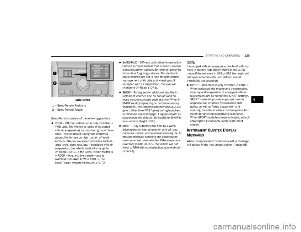
Selec-Terrain
Selec-Terrain consists of the following positions:
ROCK – Off-road calibration is only available in
4WD LOW. The vehicle is raised (if equipped
with air suspension) for improved ground clear -
ance. Traction-based tuning with improved
steerability for use on high traction off-road
surfaces. Use for low speed obstacles such as
large rocks, deep ruts, etc. If equipped with air
suspension, the vehicle level will change to
Off-Road 2 (OR2). If the Selec-Terrain switch is
in ROCK mode, and the transfer case is
switched from 4WD LOW to 4WD HI, the
Selec-Terrain system will return to AUTO.
SAND/MUD – Off-road calibration for use on low
traction surfaces such as mud or sand. Driveline
is maximized for traction. Some binding may be
felt on less forgiving surfaces. The electronic
brake controls are set to limit traction control
management of throttle and wheel spin. If
equipped with air suspension, the level will
change to Off-Road 1 (OR1).
SNOW – Tuning set for additional stability in
inclement weather. Use on and off-road on
loose traction surfaces such as snow. When in
SNOW mode (depending on certain operating
conditions), the transmission may use SECOND
gear (rather than FIRST gear) during launches,
to minimize wheel slippage. If equipped with air
suspension, the default ride height for SNOW is
Normal Ride Height (NRH).
AUTO – Fully automatic full-time four-wheel
drive operation can be used on and off-road.
Balances traction with seamless steering feel to
provide improved handling and acceleration
over two-wheel drive vehicles. If the suspension
is already in OR1 or OR2, the vehicle will not
lower to NRH with Auto selection as to maintain
capability.
NOTE:If equipped with air suspension, the level will only
raise to Normal Ride Height (NRH) in the AUTO
mode. If the vehicle is in OR1 or OR2 the height will
not lower automatically until defined speed
thresholds are exceeded.
SPORT – This mode is only available in 4WD HI.
When activated, the engine and transmission,
steering and suspension (if equipped with air
suspension) are all set to their SPORT settings.
SPORT mode will provide improved throttle
response and modified transmission shift
points as well as firmer suspension and
steering, the vehicle will also be dropped to Aero
Height for an enhanced driving experience.
When SPORT mode has been activated, an indi -
cator light will illuminate in the instrument
cluster.
INSTRUMENT CLUSTER DISPLAY
M
ESSAGES
When the appropriate conditions exist, a message
will appear in the instrument cluster Ú page 98.
1 — Selec-Terrain Positions
2 — Selec-Terrain Toggle
4
23_WL_OM_EN_USC_t.book Page 135
Page 139 of 424

STARTING AND OPERATING137
Normal Ride Height (NRH) 0.0 inches (0 mm) –
This is the standard position of the suspension
and is meant for normal driving.
Aero Height (Lowers the vehicle approximately
-0.8 inches [-21 mm] Front and -1.0 inches
[-25 mm] Rear) – This position provides
improved aerodynamics by lowering the vehicle.
The vehicle will automatically enter Aero when
the vehicle speed remains between 62 mph
(100 km/h) and 66 mph (106 km/h) for greater
than 20 seconds or if the vehicle speed exceeds
66 mph (106 km/h). The vehicle will return to
NRH from Aero if the vehicle speed remains
between 30 mph (48 km/h) and 35 mph
(56 km/h) for greater than 20 seconds or if the
vehicle speed falls below 30 mph (48 km/h).
The vehicle will enter Aero, regardless of vehicle
speed if the vehicle is in SPORT mode.
Entry/Exit Height (Lowers the vehicle approxi -
mately -1.8 inches [-46 mm] Front and
-2.0 inches [-50 mm] Rear) – This position
lowers the vehicle for easier passenger entry
and exit as well as lowering the rear of the
vehicle for easier loading and unloading of
cargo. To enter Entry/Exit, push the DOWN
button twice from NRH while the vehicle speed
is below 4 mph (6 km/h). To exit Entry/Exit,
push the UP button twice while in Entry/Exit or
drive the vehicle over 6 mph (10 km/h).
NOTE:Automatic lowering of the vehicle into Entry/Exit
can be enabled through the Uconnect Touch -
screen Radio by selecting the “Auto Entry/Exit”
setting. If this feature is enabled, the vehicle will
only lower if the gear selector is in PARK, the
terrain switch is in AUTO, the transfer case is in
AUTO and the vehicle level is either in Normal or
Aero Height. The vehicle will not automatically
lower to Entry/Exit height if the air suspension level
is in OR2 or OR1. If the vehicle is equipped with
Intrusion Theft Module (ITM), the lowering will be
suppressed when the ignition is switched OFF and
the door is open to prevent setting the alarm off.
The Selec-Terrain system will automatically change
the vehicle to the proper height based on the
position of the Selec-Terrain switch. The height can
be changed from the default Selec-Terrain setting
by normal use of the air suspension buttons
Ú page 134.
The system requires that the engine be running for
all changes. When lowering the vehicle all of the
doors must be closed. If a door is opened at any
time while the vehicle is lowering the change will
not be completed until the open door(s) is/are
closed.
The Quadra-Lift Air Suspension system uses a
lifting and lowering pattern which keeps the
headlights from incorrectly shining into oncoming
traffic. When raising the vehicle, the rear of the vehicle will move up first and then the front. When
lowering the vehicle, the front will move down first
and then the rear.
After the engine is turned off, it may be noticed that
the air suspension system operates briefly; this is
normal. The system is correcting the position of the
vehicle to ensure a proper appearance.
To assist with changing a spare tire, the
Quadra-Lift Air Suspension system has a feature
which allows the automatic leveling to be disabled
Ú
page 204.
Default Ride Height
Select Aero Height or Normal Ride Height as the
default for all vehicle speeds and operation.
This is the selected height that the suspension
will level for speed changes (e.g. raising from
Entry/Exit Height at speed, lowering from Off
Road Height at speed, etc.).
Default ride height can be changed by manually
adjusting the ride height switch to Normal Ride
Height or Aero Height and staying in the
selected height for 2.5 seconds. It will be stored
as the default ride height and the height will be
maintained until a new default ride height is
selected.
If equipped with a touchscreen radio, all enabling/
disabling of air suspension features must be done
through the radio Ú page 204.
4
23_WL_OM_EN_USC_t.book Page 137
Page 141 of 424

STARTING AND OPERATING139
pushed multiple times. Each toggle down will lower
the requested level by one position down to a
minimum of Entry/Exit Height or the lowest
position allowed based on current conditions (i.e.
vehicle speed, etc.)
Automatic height changes will occur based on
vehicle speed and the current vehicle height. The
indicator lamps and instrument cluster display
messages will operate the same for automatic
changes and user requested changes.
Off-Road 2 (OR2) Ride Height – Indicator lamps
1 through 5 will be illuminated.
Off-Road 1 (OR1) Ride Height – Indicator lamps
2 through 5 will be illuminated.
Normal Ride Height (NRH) – Indicator lamps 3
through 5 will be illuminated.
Aero Ride Height– Indicator lamps 4 and 5 will
be illuminated.
Entry/Exit Ride Height– Indicator lamp 5 will be
illuminated.
Transport Mode – Indicator lamp 5 will be illumi -
nated. Driving above 3 mph (5 km/h) or dese -
lecting setting in the radio will disable Transport
Mode.
Tire/Jack Mode – Indicator lamps 3 through
5 will be illuminated. Driving above 5 mph
(8 km/h) or deselecting setting in the radio will
disable Tire/Jack Mode.
Wheel Alignment Mode – Indicator lamps 3
through 5 will be illuminated. Driving above
5 mph (8 km/h) or deselecting setting in the
radio will disable Wheel Alignment Mode.
FUEL SAVER TECHNOLOGY 5.7L ONLY —
IF EQUIPPED
This feature offers improved fuel economy by
shutting off four of the engine's eight cylinders
during light load and cruise conditions. The system
is automatic with no driver inputs or additional
driving skills required.
NOTE:This system may take some time to return to full
functionality after a battery disconnect.
POWER STEERING
The electric power steering system provides
enhanced vehicle response and increased ease of
maneuverability in tight spaces. The power
steering system adapts to different driving
conditions. If the electric power steering system
experiences a fault that prevents it from providing
assistance, you will still have the ability to steer the
vehicle manually.
NOTE:Alternate electric power steering efforts (Normal,
Comfort and Sport) can be selected through the
Uconnect System Ú page 204. If SPORT mode is
selected, steering efforts are optimized for sporty
driving.
If the Electric Power Steering warning
icon is displayed and the “Service Power
Steering” or the “Power Steering Assist
Off – Service System” message is
displayed within the instrument cluster display,
this indicates the vehicle needs to be taken to the
dealer for service Ú page 108.
NOTE:
Even if the power steering assistance is no
longer operational, it is still possible to steer the
vehicle. Under these conditions there will be a
substantial increase in steering effort, espe -
cially at low speeds and during parking maneu -
vers.
If the condition persists, see an authorized
dealer for service.
WARNING!
Continued operation with reduced assist could
pose a safety risk to yourself and others. Service
should be obtained as soon as possible.
4
23_WL_OM_EN_USC_t.book Page 139
Page 142 of 424

140STARTING AND OPERATING
If the Steering icon is displayed and the “Power
Steering System Over Temp” message is displayed
on the instrument cluster screen, they indicate
that extreme steering maneuvers may have
occurred which caused an over temperature
condition in the electric power steering system.
Once driving conditions are safe, pull over and let
the vehicle idle for a few moments until the icon
and message turn off.
STOP/START SYSTEM — IF EQUIPPED
The Stop/Start function is designed to reduce fuel
consumption. The system will stop the engine
automatically during a vehicle stop if the required
conditions are met. Releasing the brake pedal or
pressing the accelerator pedal will automatically
re-start the engine.
This vehicle has been upgraded with a heavy-duty
starter, enhanced battery, and other upgraded
engine parts, to handle the additional engine
starts.
AUTOSTOP MODE
The Stop/Start feature is enabled after every
normal customer engine start. At that time, the
system will go into STOP/START READY and if all
other conditions are met, can go into a STOP/
START AUTOSTOP ACTIVE Autostop mode. To Activate The Autostop Mode, The Following
Must Occur:
The system must be in STOP/START READY
state. A STOP/START READY message will be
displayed in the instrument cluster display
within the Stop/Start section Ú
page 98.
The vehicle must be completely stopped.
The gear selector must be in a forward gear and
the brake pedal pressed.
The engine will shut down, the tachometer will
move to the zero position and the Stop/Start
telltale will illuminate indicating you are in
Autostop. Customer settings will be maintained
upon return to an engine running condition.
POSSIBLE REASONS THE ENGINE DOES
N
OT AUTOSTOP
Prior to engine shut down, the system will check
many safety and comfort conditions to see if they
are fulfilled. Detailed information about the
operation of the Stop/Start system may be viewed
in the instrument cluster display Stop/Start
screen. In the following situations, the engine will
not stop:
Driver’s seat belt is not buckled.
Driver’s door is not closed.
Battery temperature is too warm or cold.
Battery charge is low.
The vehicle is on a steep grade.
Cabin heating or cooling is in process and an
acceptable cabin temperature has not been
achieved.
HVAC is set to full defrost mode at a high blower
speed.
HVAC is set to MAX A/C.
Engine has not reached normal operating
temperature.
The transmission is not in a forward gear.
Hood is open.
Brake pedal is not pressed with sufficient pres -
sure.
Accelerator pedal input.
Engine temperature is too high.
5 mph (8 km/h) threshold has not been
achieved from previous Autostop.
Steering angle is beyond threshold.
It may be possible for the vehicle to be driven
several times without the Stop/Start system going
into a STOP/START READY state under more
extreme conditions of the previously listed items.
23_WL_OM_EN_USC_t.book Page 140
Page 143 of 424
STARTING AND OPERATING141
TO START THE ENGINE WHILE IN
A
UTOSTOP MODE
While in a forward gear, the engine will start when
the brake pedal is released or the throttle pedal is
pressed. The transmission will automatically
re-engage upon engine restart.
Conditions That Will Cause The Engine To Start
Automatically While In Autostop Mode:
The transmission selector is moved out of
DRIVE.
To maintain cabin temperature comfort.
HVAC is set to full defrost mode.
HVAC system temperature or fan speed is
manually adjusted.
Battery voltage drops too low.
Stop/Start OFF switch is pushed.
A Stop/Start system error occurs.
Steering angle is beyond threshold.
TO MANUALLY TURN OFF THE STOP/
S
TART SYSTEM
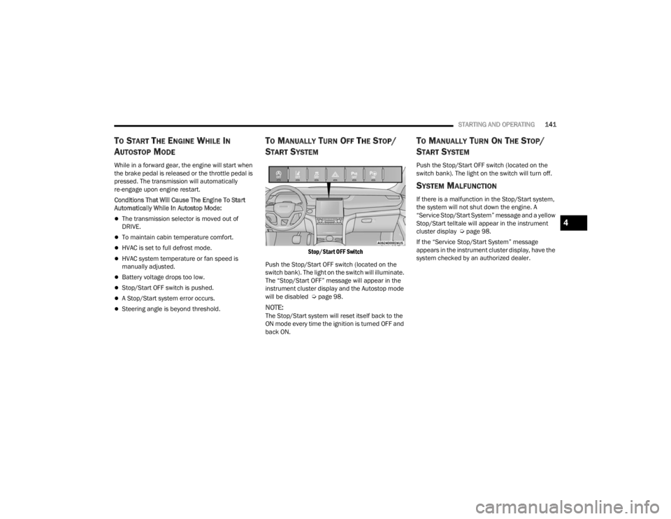
Stop/Start OFF Switch
Push the Stop/Start OFF switch (located on the
switch bank). The light on the switch will illuminate.
The “Stop/Start OFF” message will appear in the
instrument cluster display and the Autostop mode
will be disabled Ú page 98.
NOTE:The Stop/Start system will reset itself back to the
ON mode every time the ignition is turned OFF and
back ON.
TO MANUALLY TURN ON THE STOP/
S
TART SYSTEM
Push the Stop/Start OFF switch (located on the
switch bank). The light on the switch will turn off.
SYSTEM MALFUNCTION
If there is a malfunction in the Stop/Start system,
the system will not shut down the engine. A
“Service Stop/Start System” message and a yellow
Stop/Start telltale will appear in the instrument
cluster display Ú page 98.
If the “Service Stop/Start System” message
appears in the instrument cluster display, have the
system checked by an authorized dealer.
4
23_WL_OM_EN_USC_t.book Page 141
Page 148 of 424
146STARTING AND OPERATING
To Vary The Speed Setting
To Increase Or Decrease The Set Speed
After setting a speed, you can increase the set
speed by pushing the SET (+) button, or decrease
speed by pushing the SET (-) button.
U.S. Speed (mph)
Pushing the SET (+) , or SET (-) button once will
result in a 1 mph speed adjustment. Each
subsequent tap of the button results in an
adjustment of 1 mph.
If the button is continually pushed, the set
speed will continue to adjust in 5 mph incre -
ments until the button is released. The new set
speed is reflected in the instrument cluster
display.
Metric Speed (km/h)
Pushing the SET (+) , or SET (-) button once will
result in a 1 km/h speed adjustment. Each
subsequent tap of the button results in an
adjustment of 1 km/h.
If the button is continually pushed, the set
speed will continue to adjust in 10 km/h incre -
ments until the button is released. The new set
speed is reflected in the instrument cluster
display.
NOTE:When you override and push the SET (+) button or
SET (-) button, the new set speed will be the current
speed of the vehicle.
When ACC Is Active
When you use the SET (-) button to decelerate, if
the engine’s braking power does not slow the
vehicle sufficiently to reach the set speed, the
brake system will automatically slow the
vehicle.
The ACC system decelerates the vehicle to a full
stop when following the vehicle in front. If your
vehicle follows the vehicle in front to a standstill,
after two seconds the driver will either have to
push the RES (resume) button, or apply the
accelerator pedal to reengage the ACC to the
existing set speed.
The ACC system maintains set speed when
driving uphill and downhill. However, a slight
speed change on moderate hills is normal. In
addition, downshifting may occur while climbing
uphill or descending downhill. This is normal
operation and necessary to maintain set speed.
When driving uphill and downhill, the ACC
system will cancel if the braking temperature
exceeds normal range (overheated).
Setting The Following Distance In ACC
The specified following distance for ACC can be set
by varying the distance setting between four bars
(longest), three bars (long), two bars (medium) and
one bar (short). Using this distance setting and the
vehicle speed, ACC calculates and sets the
distance to the vehicle ahead. This distance
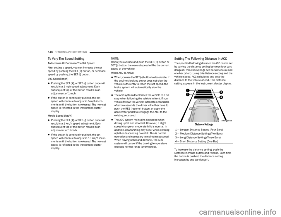
setting appears in the instrument cluster display.
Distance Settings
To increase the distance setting, push the
Distance Increase button and release. Each time
the button is pushed, the distance setting
increases by one bar (longer). 1 — Longest Distance Setting (Four Bars)
2 — Medium Distance Setting (Two Bars)
3 — Long Distance Setting (Three Bars)
4 — Short Distance Setting (One Bar)
23_WL_OM_EN_USC_t.book Page 146
Page 186 of 424
184STARTING AND OPERATING
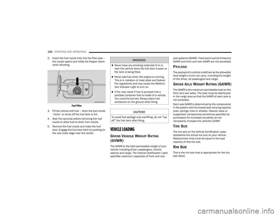
2. Insert the fuel nozzle fully into the filler pipe – the nozzle opens and holds the flapper doors
while refueling.
Fuel Filler
3. Fill the vehicle with fuel – when the fuel nozzle “clicks” or shuts off the fuel tank is full.
4. Wait five seconds before removing the fuel nozzle to allow fuel to drain from nozzle.
5. Remove the fuel nozzle and close the fuel door. Engage the fuel door latch by pushing on
the rear outer edge near the center.
VEHICLE LOADING
GROSS VEHICLE WEIGHT RATING
(GVWR)
The GVWR is the total permissible weight of your
vehicle including driver, passengers, vehicle,
options and cargo. The Vehicle Certification Label
specifies maximum capacities of front and rear axle systems (GAWR). Total load must be limited so
GVWR and front and rear GAWR are not exceeded.
PAYLOAD
The payload of a vehicle is defined as the allowable
load weight a truck can carry, including the weight
of the driver, all passengers and cargo.
GROSS AXLE WEIGHT RATING (GAWR)
The GAWR is the maximum permissible load on the
front and rear axles. The load must be distributed
in the cargo area so that the GAWR of each axle is
not exceeded.
Each axle GAWR is determined by the components
in the system with the lowest load carrying capacity
(axle, springs, tires or wheels). Heavier axles or
suspension components sometimes specified by
purchasers for increased durability do not
necessarily increase the vehicle's GVWR.
TIRE SIZE
The tire size on the Vehicle Certification Label
represents the actual tire size on your vehicle.
Replacement tires must be equal to the load
capacity of this tire size.
RIM SIZE
This is the rim size that is appropriate for the tire
size listed.
WARNING!
Never have any smoking materials lit in or
near the vehicle when the fuel door is open or
the tank is being filled.
Never add fuel when the engine is running.
This is in violation of most state and federal
fire regulations and may cause the Malfunc
-
tion Indicator Light to turn on.
A fire may result if fuel is pumped into a
portable container that is inside of a vehicle.
You could be burned. Always place fuel
containers on the ground while filling.
CAUTION!
To avoid fuel spillage and overfilling, do not “top
off” the fuel tank after filling.
23_WL_OM_EN_USC_t.book Page 184
Page 188 of 424
186STARTING AND OPERATING
(Continued)
Gross Combination Weight Rating (GCWR)
The GCWR is the total allowable weight of your
vehicle and trailer when weighed in combination.
Gross Axle Weight Rating (GAWR)
The GAWR is the maximum capacity of the front
and rear axles. Distribute the load over the front
and rear axles evenly. Make sure that you do not
exceed either front or rear GAWR Úpage 184.
Tongue Weight (TW)
The TW is the downward force exerted on the hitch
ball by the trailer. You must consider this as part of
the load on your vehicle.
Trailer Frontal Area
The frontal area is the maximum height multiplied
by the maximum width of the front of a trailer.
Trailer Sway Control (TSC)
The TSC can be a mechanical telescoping link that
can be installed between the hitch receiver and the
trailer tongue that typically provides adjustable
friction associated with the telescoping motion to
dampen any unwanted trailer swaying motions
while traveling.
The electronic TSC (if equipped) recognizes a
swaying trailer and automatically applies individual
wheel brakes and/or reduces engine power to
attempt to eliminate the trailer sway.
Weight-Carrying Hitch
A weight-carrying hitch supports the trailer tongue
weight, just as if it were luggage located at a hitch
ball or some other connecting point of the vehicle.
These kinds of hitches are used to tow small and
medium sized trailers.
Weight-Distributing Hitch
A weight-distributing system works by applying
leverage through spring (load) bars. They are
typically used for heavier loads to distribute trailer
tongue weight to the tow vehicle's front axle and
the trailer axle(s). When used in accordance with
the manufacturer's directions, it provides for a
more level ride, offering more consistent steering
and brake control thereby enhancing towing
safety. The addition of a friction/hydraulic sway
control also dampens sway caused by traffic and
crosswinds and contributes positively to tow
vehicle and trailer stability. Trailer Sway Control
(TSC) and a weight-distributing (load equalizing)
hitch are recommended for heavier Tongue
Weights (TW) and may be required depending on
vehicle and trailer configuration/loading to comply
with Gross Axle Weight Rating (GAWR)
requirements.
WARNING!
It is important that you do not exceed the
maximum front or rear GAWR. A dangerous
driving condition can result if either rating is
exceeded. You could lose control of the vehicle
and have a collision.
WARNING!
If the gross trailer weight is 5,000 lb
(2,267 kg) or more, it is recommended to use
a weight-distributing hitch to ensure stable
handling of your vehicle. If you use a standard
weight-carrying hitch, you could lose control of
your vehicle and cause a collision.
23_WL_OM_EN_USC_t.book Page 186
Page 189 of 424
STARTING AND OPERATING187
RECOMMENDED DISTRIBUTION HITCH
ADJUSTMENT
1. Verify that the vehicle is at the Normal Ride
Height.
NOTE:The vehicle must remain in the engine run position
with all doors closed while attaching a trailer for
proper leveling of the air suspension system.
2. Position the vehicle to be ready to connect to the trailer (do not connect the trailer). 3. For vehicles equipped with Quadra-Lift air
suspension, use the touchscreen radio
settings to enable Tire/Jack mode. Tire/Jack
mode will be canceled and the procedure must
be restarted if the vehicle is driven at speeds
above 5mph (8 km/h).
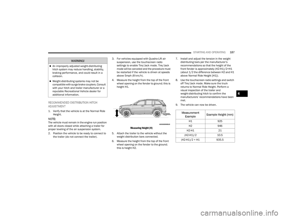
4. Measure the height from the top of the front wheel opening on the fender to ground; this is
height H1.
Measuring Height (H)
5. Attach the trailer to the vehicle without the weight distribution bars connected.
6. Measure the height from the top of the front wheel opening on the fender to the ground;
this is height H2. 7. Install and adjust the tension in the weight
distributing bars per the manufacturer’s
recommendations so that the height of the
front fender is approximately (H2-H1)/2+H1
(about 1/2 the difference between H2 and H1
above Normal Ride Height [H1]).
8. Use the touchscreen radio settings and switch off Tire/Jack mode. Make sure the truck
returns to Normal Ride Height. Perform a
visual inspection of the trailer and
weight-distributing hitch to confirm the
manufacturers’ recommendations have been
met.
9. The vehicle can now be driven.
An improperly adjusted weight-distributing
hitch system may reduce handling, stability,
braking performance, and could result in a
collision.
Weight-distributing systems may not be
compatible with surge brake couplers. Consult
with your hitch and trailer manufacturer or a
reputable Recreational Vehicle dealer for
additional information.
WARNING!
Measurement Example Example Height (mm)
H1
925
H2 946
H2-H1 21
(H2-H1)/2 10.5
(H2-H1)/2 + H1 935.5
4
23_WL_OM_EN_USC_t.book Page 187
Page 191 of 424

STARTING AND OPERATING189
TRAILER TOWING WEIGHTS (MAXIMUM TRAILER WEIGHT RATINGS)
Grand Cherokee — 2nd Row Seats
Engine ModelGCWRFrontal Area Maximum GTW Maximum Trailer TW
(See Note)
2.0L AWD Without Trailer Tow
Prep Group 9,625 lb (4,366 kg) 30 sq ft (2.79 sq m) 3,500 lb (1,588 kg) 350 lb (159 kg)
2.0L AWD With Trailer Tow
Prep Group 12,125 lb (5,568 kg) 40 sq ft (3.72 sq m) 6,000 lb (2,722 kg) 600 lb (272 kg)
3.6L AWD Without Trailer Tow
Prep Group 8,600 lb (3,901 kg) 30 sq ft (2.79 sq m) 3,500 lb (1,588 kg) 350 lb (159 kg)
3.6L AWD With Trailer Tow
Prep Group 11,300 lb (5,126 kg) 40 sq ft (3.72 sq m) 6,200 lb (2,812 kg) 620 lb (281 kg)
3.6L RWD Without Trailer Tow
Prep Group 8,500 lb (3,856 kg) 30 sq ft (2.79 sq m) 3,500 lb (1,588 kg) 350 lb (159 kg)
3.6L RWD With Trailer Tow
Prep Group 11,200 lb (5,080 kg) 40 sq ft (3.72 sq m) 6,200 lb (2,812 kg) 620 lb (281 kg)
5.7L AWD With Trailer Tow
Prep Group 12,700 lb (5,761 kg) 40 sq ft (3.72 sq m) 7,200 lb (3,266 kg) 720 lb (327 kg)
Refer to local laws for maximum trailer towing speeds.
4
23_WL_OM_EN_USC_t.book Page 189