sensor JEEP GRAND CHEROKEE 2023 Owners Manual
[x] Cancel search | Manufacturer: JEEP, Model Year: 2023, Model line: GRAND CHEROKEE, Model: JEEP GRAND CHEROKEE 2023Pages: 424, PDF Size: 15.48 MB
Page 7 of 424

5
FOUR-WHEEL DRIVE OPERATION...................... 131 Quadra-Trac I Operating Instructions/
Precautions — If Equipped ............................ 131
Quadra-Trac II Operating Instructions/
Precautions —If Equipped ............................. 131
Shift Positions................................................ 132
Shifting Procedures ....................................... 132
Quadra-Trac II System —If Equipped ............ 133Electronic Sway Bar Disconnect —
If Equipped .................................................... 133
SELEC-TERRAIN — IF EQUIPPED ....................... 134
Selec-Terrain Mode Selection ...................... 134Instrument Cluster Display Messages ......... 135
QUADRA-LIFT — IF EQUIPPED ............................ 136
Description..................................................... 136
Air Suspension Modes .................................. 138
Instrument Cluster Display Messages ......... 138Operation ....................................................... 138
FUEL SAVER TECHNOLOGY 5.7L ONLY —
IF EQUIPPED ......................................................... 139
POWER STEERING .............................................. 139 STOP/START SYSTEM — IF EQUIPPED ............. 140
Autostop Mode .............................................. 140
Possible Reasons The Engine Does Not
Autostop......................................................... 140
To Start The Engine While In Autostop Mode......141
To Manually Turn Off The Stop/Start System .....141
To Manually Turn On The Stop/Start System......141
System Malfunction ...................................... 141
CRUISE CONTROL SYSTEMS ............................ 142
Adaptive Cruise Control (ACC) ...................... 142
TRAFFIC SIGN ASSIST SYSTEM —
IF EQUIPPED ........................................................ 151
Activation/Deactivation ................................ 151Traffic Sign Assist Modes ............................. 151
Indications On The Display ........................... 151
ACTIVE DRIVING ASSIST SYSTEM —
IF EQUIPPED ........................................................ 152
Operation ....................................................... 152
Turning Active Driving Assist On Or Off ........ 155
Indications On The Display ........................... 156System Status ............................................... 157
System Operation/Limitations ..................... 158 PARKSENSE FRONT/REAR PARK ASSIST
SYSTEM — IF EQUIPPED ..................................... 159
ParkSense Sensors ....................................... 160
ParkSense Display ........................................ 160
ParkSense Warning Display ......................... 163
Enabling And Disabling ParkSense.............. 163
Service The ParkSense Park Assist System ...163
Cleaning The ParkSense System ................. 164
ParkSense System Usage Precautions........ 164Side Distance Warning System .................... 165
PARKSENSE ACTIVE PARK ASSIST SYSTEM —
IF EQUIPPED ......................................................... 166
Enabling And Disabling The ParkSense Active
Park Assist System........................................ 167
Parallel/Perpendicular Parking Space
Assistance Operation .................................... 168
Exiting The Parking Space ............................ 170
ACTIVE LANE MANAGEMENT SYSTEM —
IF EQUIPPED ........................................................ 171
Active Lane Management Operation ........... 171
Turning Active Lane Management On Or Off ..172
Active Lane Management Warning Message ..... 172
Changing Active Lane Management Status ...174
23_WL_OM_EN_USC_t.book Page 5
Page 16 of 424
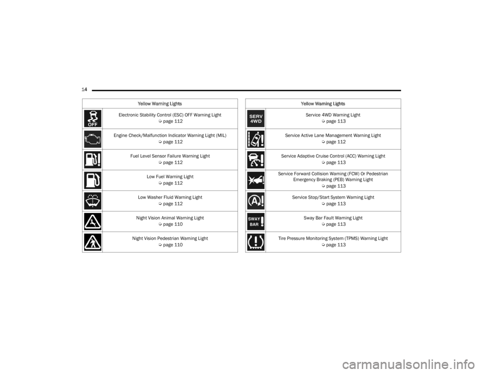
14 Electronic Stability Control (ESC) OFF Warning Light Úpage 112
Engine Check/Malfunction Indicator Warning Light (MIL) Úpage 112
Fuel Level Sensor Failure Warning Light Úpage 112
Low Fuel Warning Light Úpage 112
Low Washer Fluid Warning Light Úpage 112
Night Vision Animal Warning Light Úpage 110
Night Vision Pedestrian Warning Light Úpage 110
Yellow Warning Lights
Service 4WD Warning Light
Úpage 113
Service Active Lane Management Warning Light Úpage 112
Service Adaptive Cruise Control (ACC) Warning Light Úpage 113
Service Forward Collision Warning (FCW) Or Pedestrian Emergency Braking (PEB) Warning Light
Úpage 113
Service Stop/Start System Warning Light Úpage 113
Sway Bar Fault Warning Light Úpage 113
Tire Pressure Monitoring System (TPMS) Warning Light Úpage 113
Yellow Warning Lights
23_WL_OM_EN_USC_t.book Page 14
Page 67 of 424
GETTING TO KNOW YOUR VEHICLE65
Mist
Use the Mist feature when weather conditions
make occasional usage of the wipers necessary.
Push the lever upward to the MIST position and
release for a single wiping cycle.
NOTE:The Mist feature does not activate the washer
pump; therefore, no washer fluid will be sprayed on
the windshield. The washer function must be used
in order to spray the windshield with washer fluid.
For information on wiper care and replacement,
see Úpage 343.
RAIN SENSING WIPERS — IF EQUIPPED
This feature senses rain or snowfall on the
windshield and automatically activates the wipers.
Rotate the end of the windshield wiper lever to one
of the four detent positions to activate this feature.
The sensitivity of the system is adjustable from the
windshield wiper lever. Wiper sensitivity position 1
is the least sensitive, and wiper sensitivity position
4 is the most sensitive.
NOTE:
The Rain Sensing feature will not operate when
the wiper switch is in the low, high, or OFF posi -
tion. Only in one of the intermittent positions.
The Rain Sensing feature may not function prop -
erly when ice or dried saltwater is present on the
windshield.
Use of products containing wax or silicone may
reduce rain sensor performance.
The Rain Sensing feature can be turned on and
off through the Uconnect system Ú page 204.The Rain Sensing system has protective features
for the wiper blades and arms. It will not operate
under the following conditions:
Low Temperature Wipe Inhibit
— The Rain
Sensing feature will not operate when the igni -
tion is first placed in the ON/RUN position, when
the vehicle is stationary and the outside
temperature is below 32°F (0°C), unless the
wiper control on the windshield wiper lever is
moved, the vehicle speed becomes greater than
3 mph (5 km/h) or the outside temperature
rises above freezing.
Neutral Wipe Inhibit — The Rain Sensing feature
will not operate when the ignition is placed in
the ON/RUN position, when the transmission
gear selector is in the NEUTRAL position and the
vehicle speed is less than 3 mph (5 km/h),
unless the wiper control on the windshield wiper
lever is moved, the vehicle speed is greater than
3 mph (5 km/h) or the gear selector is moved
out of the NEUTRAL position.
Remote Start Mode Inhibit — On vehicles
equipped with the Remote Start system, Rain
Sensing wipers are not operational when the
vehicle is in the Remote Start mode. Once the
operator is in the vehicle and has placed the
ignition switch in the ON/RUN position, rain
sensing wiper operation can resume, if it has
been selected, and no other inhibit conditions
(mentioned previously) exist.
WARNING!
Sudden loss of visibility through the windshield
could lead to a collision. You might not see other
vehicles or other obstacles. To avoid sudden
icing of the windshield during freezing weather,
warm the windshield with the defroster before
and during windshield washer use.
2
23_WL_OM_EN_USC_t.book Page 65
Page 91 of 424
GETTING TO KNOW YOUR VEHICLE89
ADJUSTABLE POWER LIFTGATE HEIGHT
The maximum height that the liftgate will open can
be adjusted and saved so that the liftgate will only
open to the desired height. To set a desired height,
proceed as follows:
1. Open the liftgate fully, then manually pull
down on the liftgate to the desired height.
2. Push and hold the liftgate close button, located on the left side trim panel inside the
cargo area, for three seconds. An audible
chime will be emitted to let you know the
height has been saved.
To set the saved height setting to a new setting,
proceed as follows:
1. Open the liftgate, then manually push the liftgate upward to its full open position.
2. Manually pull the liftgate down to the new desired height and hold the liftgate close
button for three seconds until the audible
chime is emitted. Power Liftgate Malfunction Procedure:
1. In the event of a power malfunction to the
liftgate, the liftgate can be released by
accessing the service release feature in the
latch. This can be done using a 3 mm
diameter screwdriver.
Liftgate Service Release
2. From inside the gate, an eyelet can be seen. Place the screwdriver in the eyelet.
3. Rotate the screwdriver handle to actuate the lever and release the latch.
4. If liftgate is left open for an extended period of time, the liftgate may need to be closed
manually to reset power liftgate functionality.
HANDS-FREE LIFTGATE — IF EQUIPPED
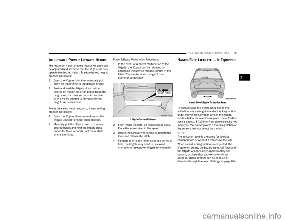
Hands-Free Liftgate Activation Zone
To open or close the liftgate using hands-free
activation, use a straight in and out kicking motion
under the vehicle activation zone in the general
location below the rear license plate. The activation
zone is about 1.8 ft (0.5 m) from side to side. Do not
move your foot sideways or in a sweeping motion or
the sensors may not detect the motion.
NOTE:The activation zone is the same for vehicles
equipped with or without a trailer tow package.
When a valid kicking motion is completed, the
liftgate will chime, the hazard lights will flash and
the liftgate will open after approximately one
second, or close after approximately three
seconds. These settings can be enabled or
disabled through Uconnect Settings Ú page 204.
2
23_WL_OM_EN_USC_t.book Page 89
Page 92 of 424
90GETTING TO KNOW YOUR VEHICLE
NOTE:
Opening or closing the Hands-Free Liftgate
requires a valid Passive Entry key fob within 5 ft
(1.5 m) of the liftgate handle. If a valid Passive
Entry key fob is not within 5 ft (1.5 m), the lift -
gate will not respond to any kicks.
The Hands-Free Liftgate feature may be turned
on or off through the Uconnect system
Ú page 204.
The Hands-Free Liftgate feature should be
turned off during jacking, tire changing, manual
car wash, and vehicle service.
The Hands-Free Liftgate feature can be acti -
vated by any metallic object making a similar
in-and-out motion under the rear fascia/
bumper, such as cleaning using a metal broom.
The Hands-Free Liftgate will only operate when
the transmission is in PARK.
If anything obstructs the Hands-Free Liftgate
while it is opening or closing, the liftgate will
automatically reverse to the closed/open posi -
tion, provided it meets sufficient resistance.
There are pinch sensors attached to the side of
the liftgate opening. Light pressure anywhere
along these strips will cause the liftgate to
return to the open position.
If the power liftgate encounters multiple
obstructions within the same cycle, the system
will automatically stop. If this occurs, the liftgate
must be operated manually.
The power liftgate will release, but not power
open, in temperatures below −12°F (−24°C).
Be sure to remove any buildup of snow or ice
from the liftgate before opening the liftgate.
If the liftgate is left open for an extended period
of time (approximately one hour), the liftgate
may need to be closed manually to reset power
liftgate functionality. Gas props support the liftgate in the open position.
However, because the gas pressure drops with
temperature, it may be necessary to assist the
props when opening the liftgate in cold weather.
NOTE:Allow the power system to open the liftgate.
Manually pushing or pulling the liftgate may
activate the liftgate obstacle detection feature and
stop the power operation or reverse its direction.
CARGO AREA FEATURES
Cargo Storage
The load floor is designed for a maximum load of
300 lb (136 kg).
If equipped, there may be a removable storage bin
located on the left side of the rear cargo area.
WARNING!
Driving with the liftgate open can allow
poisonous exhaust gases into your vehicle.
You and your passengers could be injured by
these fumes. Keep the liftgate closed when
you are operating the vehicle.
If you are required to drive with the liftgate
open, make sure that all windows are closed,
and the climate control blower switch is set at
high speed. Do not use the recirculation
mode.
WARNING!
During power operation, personal injury or cargo
damage may occur. Ensure the liftgate travel
path is clear. Make sure the liftgate is closed
and latched before driving away.
23_WL_OM_EN_USC_t.book Page 90
Page 108 of 424
106GETTING TO KNOW YOUR INSTRUMENT PANEL
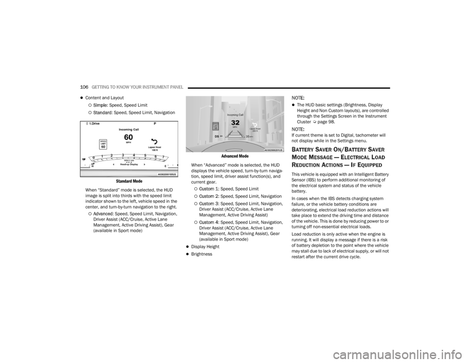
Content and Layout
Simple: Speed, Speed Limit
Standard : Speed, Speed Limit, Navigation
Standard Mode
When “Standard” mode is selected, the HUD
image is split into thirds with the speed limit
indicator shown to the left, vehicle speed in the
center, and turn-by-turn navigation to the right.
Advanced : Speed, Speed Limit, Navigation,
Driver Assist (ACC/Cruise, Active Lane
Management, Active Driving Assist), Gear
(available in Sport mode)
Advanced Mode
When “Advanced” mode is selected, the HUD
displays the vehicle speed, turn-by-turn naviga -
tion, speed limit, driver assist function(s), and
current gear.
Custom 1 : Speed, Speed Limit
Custom 2: Speed, Speed Limit, Navigation
Custom 3: Speed, Speed Limit, Navigation,
Driver Assist (ACC/Cruise, Active Lane
Management, Active Driving Assist)
Custom 4 : Speed, Speed Limit, Navigation,
Driver Assist (ACC/Cruise, Active Lane
Management, Active Driving Assist), Gear
(available in Sport mode)
Display Height
Brightness
NOTE:
The HUD basic settings (Brightness, Display
Height and Non Custom layouts), are controlled
through the Settings Screen in the Instrument
Cluster Ú page 98.
NOTE:If current theme is set to Digital, tachometer will
not display while in the Settings menu.
BATTERY SAVER ON/BATTERY SAVER
M
ODE MESSAGE — ELECTRICAL LOAD
R
EDUCTION ACTIONS — IF EQUIPPED
This vehicle is equipped with an Intelligent Battery
Sensor (IBS) to perform additional monitoring of
the electrical system and status of the vehicle
battery.
In cases when the IBS detects charging system
failure, or the vehicle battery conditions are
deteriorating, electrical load reduction actions will
take place to extend the driving time and distance
of the vehicle. This is done by reducing power to or
turning off non-essential electrical loads.
Load reduction is only active when the engine is
running. It will display a message if there is a risk
of battery depletion to the point where the vehicle
may stall due to lack of electrical supply, or will not
restart after the current drive cycle.
23_WL_OM_EN_USC_t.book Page 106
Page 114 of 424
112GETTING TO KNOW YOUR INSTRUMENT PANEL
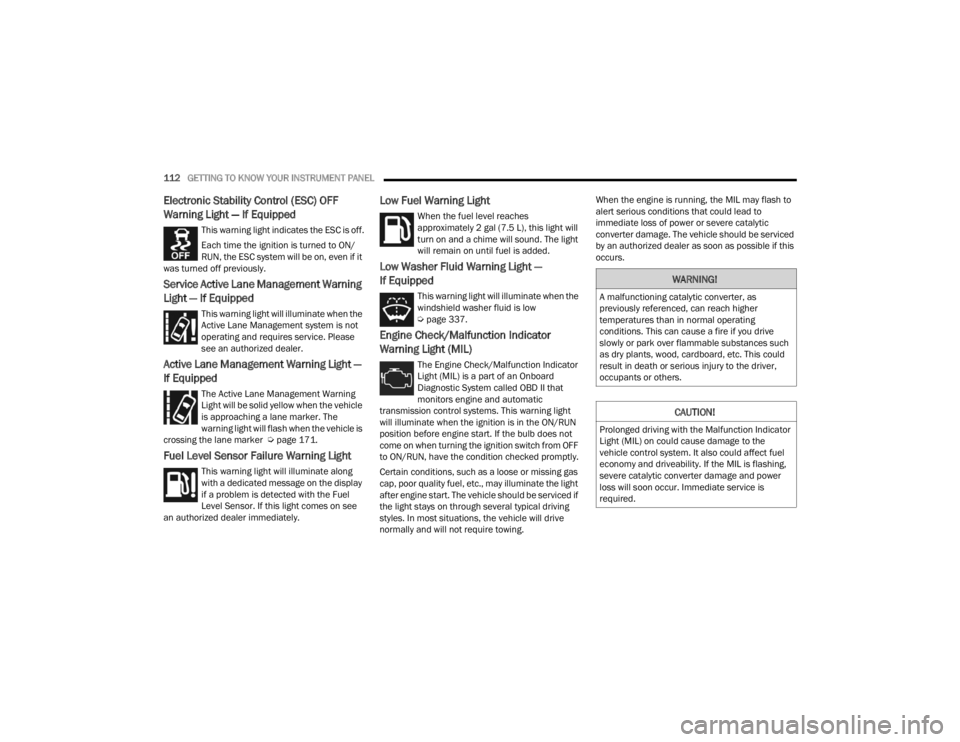
Electronic Stability Control (ESC) OFF
Warning Light — If Equipped
This warning light indicates the ESC is off.
Each time the ignition is turned to ON/
RUN, the ESC system will be on, even if it
was turned off previously.
Service Active Lane Management Warning
Light — If Equipped
This warning light will illuminate when the
Active Lane Management system is not
operating and requires service. Please
see an authorized dealer.
Active Lane Management Warning Light —
If Equipped
The Active Lane Management Warning
Light will be solid yellow when the vehicle
is approaching a lane marker. The
warning light will flash when the vehicle is
crossing the lane marker Ú page 171.
Fuel Level Sensor Failure Warning Light
This warning light will illuminate along
with a dedicated message on the display
if a problem is detected with the Fuel
Level Sensor. If this light comes on see
an authorized dealer immediately.
Low Fuel Warning Light
When the fuel level reaches
approximately 2 gal (7.5 L), this light will
turn on and a chime will sound. The light
will remain on until fuel is added.
Low Washer Fluid Warning Light —
If Equipped
This warning light will illuminate when the
windshield washer fluid is low
Ú page 337.
Engine Check/Malfunction Indicator
Warning Light (MIL)
The Engine Check/Malfunction Indicator
Light (MIL) is a part of an Onboard
Diagnostic System called OBD II that
monitors engine and automatic
transmission control systems. This warning light
will illuminate when the ignition is in the ON/RUN
position before engine start. If the bulb does not
come on when turning the ignition switch from OFF
to ON/RUN, have the condition checked promptly.
Certain conditions, such as a loose or missing gas
cap, poor quality fuel, etc., may illuminate the light
after engine start. The vehicle should be serviced if
the light stays on through several typical driving
styles. In most situations, the vehicle will drive
normally and will not require towing. When the engine is running, the MIL may flash to
alert serious conditions that could lead to
immediate loss of power or severe catalytic
converter damage. The vehicle should be serviced
by an authorized dealer as soon as possible if this
occurs.
WARNING!
A malfunctioning catalytic converter, as
previously referenced, can reach higher
temperatures than in normal operating
conditions. This can cause a fire if you drive
slowly or park over flammable substances such
as dry plants, wood, cardboard, etc. This could
result in death or serious injury to the driver,
occupants or others.
CAUTION!
Prolonged driving with the Malfunction Indicator
Light (MIL) on could cause damage to the
vehicle control system. It also could affect fuel
economy and driveability. If the MIL is flashing,
severe catalytic converter damage and power
loss will soon occur. Immediate service is
required.
23_WL_OM_EN_USC_t.book Page 112
Page 116 of 424
114GETTING TO KNOW YOUR INSTRUMENT PANEL
also reduces fuel efficiency and tire tread life, and
may affect the vehicle’s handling and stopping
ability.
Please note that the TPMS is not a substitute for
proper tire maintenance, and it is the driver’s
responsibility to maintain correct tire pressure,
even if underinflation has not reached the level to
trigger illumination of the TPMS low tire pressure
telltale.
Your vehicle has also been equipped with a TPMS
malfunction indicator to indicate when the system
is not operating properly. The TPMS malfunction
indicator is combined with the low tire pressure
telltale. When the system detects a malfunction,
the telltale will flash for approximately one minute
and then remain continuously illuminated. This
sequence will continue upon subsequent vehicle
start-ups as long as the malfunction exists. When
the malfunction indicator is illuminated, the
system may not be able to detect or signal low tire
pressure as intended. TPMS malfunctions may
occur for a variety of reasons, including the
installation of replacement or alternate tires or
wheels on the vehicle that prevent the TPMS from
functioning properly. Always check the TPMS
malfunction telltale after replacing one or more
tires or wheels on your vehicle to ensure that the
replacement or alternate tires and wheels allow
the TPMS to continue to function properly.
YELLOW INDICATOR LIGHTS
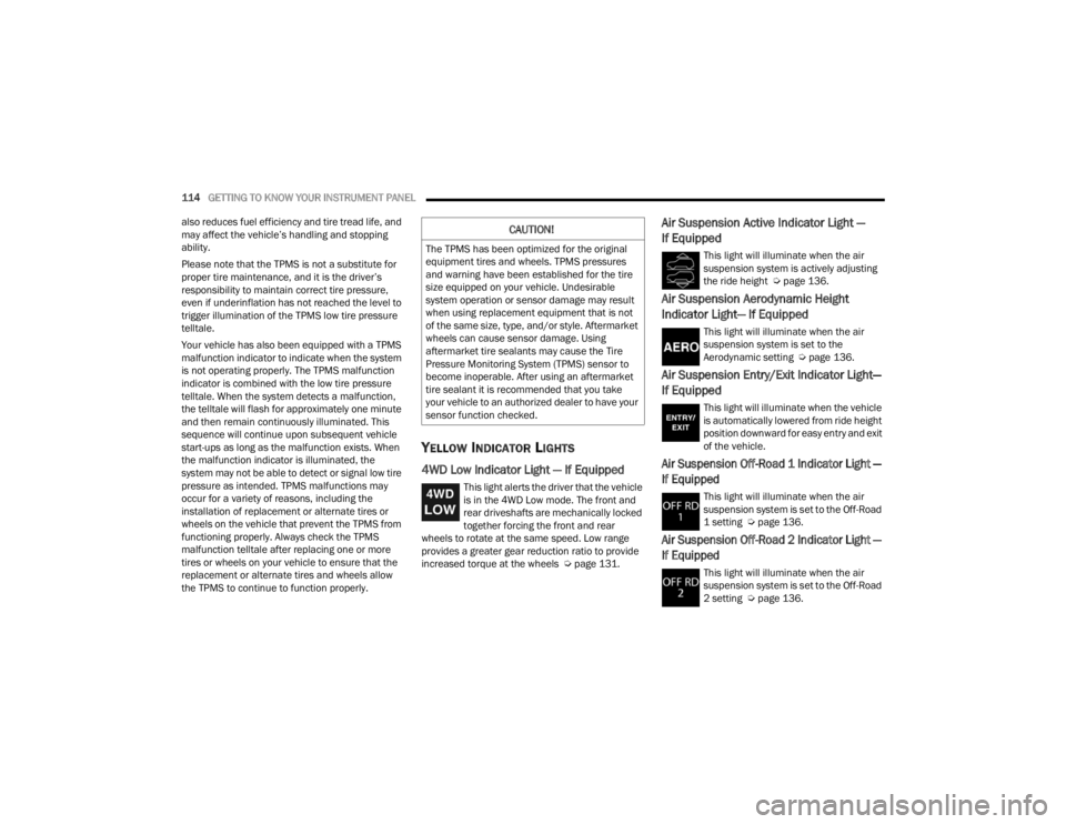
4WD Low Indicator Light — If Equipped
This light alerts the driver that the vehicle
is in the 4WD Low mode. The front and
rear driveshafts are mechanically locked
together forcing the front and rear
wheels to rotate at the same speed. Low range
provides a greater gear reduction ratio to provide
increased torque at the wheels Ú page 131.
Air Suspension Active Indicator Light —
If Equipped
This light will illuminate when the air
suspension system is actively adjusting
the ride height Úpage 136.
Air Suspension Aerodynamic Height
Indicator Light— If Equipped
This light will illuminate when the air
suspension system is set to the
Aerodynamic setting Ú page 136.
Air Suspension Entry/Exit Indicator Light—
If Equipped
This light will illuminate when the vehicle
is automatically lowered from ride height
position downward for easy entry and exit
of the vehicle.
Air Suspension Off-Road 1 Indicator Light —
If Equipped
This light will illuminate when the air
suspension system is set to the Off-Road
1 setting Úpage 136.
Air Suspension Off-Road 2 Indicator Light —
If Equipped
This light will illuminate when the air
suspension system is set to the Off-Road
2 setting Úpage 136.
CAUTION!
The TPMS has been optimized for the original
equipment tires and wheels. TPMS pressures
and warning have been established for the tire
size equipped on your vehicle. Undesirable
system operation or sensor damage may result
when using replacement equipment that is not
of the same size, type, and/or style. Aftermarket
wheels can cause sensor damage. Using
aftermarket tire sealants may cause the Tire
Pressure Monitoring System (TPMS) sensor to
become inoperable. After using an aftermarket
tire sealant it is recommended that you take
your vehicle to an authorized dealer to have your
sensor function checked.
23_WL_OM_EN_USC_t.book Page 114
Page 144 of 424
142STARTING AND OPERATING
(Continued)
CRUISE CONTROL SYSTEMS
Your vehicle is equipped with the Adaptive Cruise
Control (ACC) system which will adjust the vehicle
speed up to the preset speed to maintain a
distance with the vehicle ahead.
NOTE:In vehicles NOT equipped with the Active Driving
Assist (ADA) system:
Fixed Speed Cruise Control can be used when
ACC is not enabled, and functions as normal
cruise control.
Fixed Speed Cruise Control will not detect vehi -
cles directly ahead of you. Always be aware of
the feature selected.
Only one Cruise Control feature can operate at a
time. For example, if Fixed Speed Cruise Control
is enabled, Adaptive Cruise Control will be
unavailable, and vice versa.
ADAPTIVE CRUISE CONTROL (ACC)
Adaptive Cruise Control (ACC) increases the driving
convenience provided by Cruise Control while
traveling on highways and major roadways.
However, it is not a safety system and not designed
to prevent collisions. ACC will allow you to keep Cruise Control engaged
in light to moderate traffic conditions without the
constant need to reset your Cruise Control. ACC
utilizes a radar sensor and a forward facing
camera designed to detect a vehicle directly ahead
of you.
NOTE:
If the ACC sensor detects a vehicle ahead, ACC
will apply limited braking or acceleration (not to
exceed the original set speed) automatically to
maintain a preset following distance, while
matching the speed of the vehicle ahead.
Any chassis/suspension or tire size modifica
-
tions to the vehicle will affect the performance
of the Adaptive Cruise Control and Forward Colli -
sion Warning system.
In vehicles NOT equipped with the Active Driving
Assist system, Fixed Speed Cruise Control (ACC
not enabled) will not detect vehicles directly
ahead of you. Always be aware of the feature
selected Ú page 408.
WARNING!
Adaptive Cruise Control (ACC) is a conve -
nience system. It is not a substitute for active
driver involvement. It is always the driver’s
responsibility to be attentive of road, traffic,
and weather conditions, vehicle speed,
distance to the vehicle ahead and, most
importantly, brake operation to ensure safe
operation of the vehicle under all road condi -
tions. Your complete attention is always
required while driving to maintain safe control
of your vehicle. Failure to follow these warn -
ings can result in a collision and death or
serious personal injury.
The ACC system:
Does not react to pedestrians, oncoming
vehicles, and stationary objects (e.g., a
stationary vehicle in a traffic jam or a
disabled vehicle).
Cannot take street, traffic, and weather
conditions into account, and may be limited
upon adverse sight distance conditions.
Does not always fully recognize complex
driving conditions, which can result in
wrong or missing distance warnings.
23_WL_OM_EN_USC_t.book Page 142
Page 149 of 424
STARTING AND OPERATING147
To decrease the distance setting, push the
Distance Decrease button and release. Each time
the button is pushed, the distance setting
decreases by one bar (shorter).
If there is no vehicle ahead, the vehicle will
maintain the set speed. If a slower moving vehicle
is detected in the same lane, the instrument
cluster display will show the ACC Set With Target
Detected Indicator Light, and the system will adjust
the vehicle speed automatically to maintain the
distance setting, regardless of the set speed.
The vehicle will then maintain the set distance
until:
The vehicle ahead accelerates to a speed above
the set speed.
The vehicle ahead moves out of your lane or
view of the sensor.
The distance setting is changed.
The system disengages Ú page 144.
The maximum braking applied by ACC is limited;
however, the driver can always apply the brakes
manually, if necessary.
NOTE:The brake lights will illuminate whenever the ACC
system applies the brakes. A Proximity Warning will alert the driver if ACC
predicts that its maximum braking level is not
sufficient to maintain the set distance. If this
occurs, a visual alert “BRAKE!” will flash in the
instrument cluster display and a chime will sound
while ACC continues to apply its maximum braking
capacity.
NOTE:The “BRAKE!” screen in the instrument cluster
display is a warning for the driver to take action
and does not necessarily mean that the Forward
Collision Warning system is applying the brakes
autonomously.
Overtake Aid
When driving with Adaptive Cruise Control (ACC)
engaged and following a vehicle, the system will
provide an additional acceleration up to the ACC
set speed to assist in passing the vehicle. This
additional acceleration is triggered when the driver
utilizes the left turn signal and will only be active
when passing on the left hand side.
ACC Operation At Stop
If the ACC system brings your vehicle to a standstill
while following a vehicle ahead, your vehicle will
resume motion, without any driver interaction, if
the vehicle ahead starts moving within two
seconds of your vehicle coming to a standstill.If the vehicle in front does not start moving within
two seconds of your vehicle coming to a standstill,
the driver will either have to push the RES (resume)
button, or apply the accelerator pedal to reengage
the ACC to the existing set speed.
NOTE:
If your vehicle is at a standstill for longer than
two seconds, the system will hold brake pres
-
sure for up to 10 minutes. If no driver action is
taken after the 10 minutes, the Electric Park
Brake will be applied and the ACC system will
cancel.
While ACC is holding your vehicle at a standstill
(or the vehicle is traveling below 3 mph
(5 km/h), and the driver seat belt is unbuckled
or the driver door is opened, the Electric Park
Brake will be applied and the ACC system will
cancel.
WARNING!
When the ACC system is resumed, the driver
must ensure that there are no pedestrians,
vehicles or objects in the path of the vehicle.
Failure to follow these warnings can result in a
collision and death or serious personal injury.
4
23_WL_OM_EN_USC_t.book Page 147