ESP JEEP GRAND CHEROKEE LIMITED 2019 Owners Manual
[x] Cancel search | Manufacturer: JEEP, Model Year: 2019, Model line: GRAND CHEROKEE LIMITED, Model: JEEP GRAND CHEROKEE LIMITED 2019Pages: 626, PDF Size: 3.77 MB
Page 2 of 626

INSTALLATION OF RADIO TRANSMITTING
EQUIPMENT
Special design considerations are incorporated into this
vehicle’s electronic system to provide immunity to radio
frequency signals. Mobile two-way radios and telephone
equipment must be installed properly by trained person-
nel. The following must be observed during installation.
The positive power connection should be made directly
to the battery and fused as close to the battery as possible.
The negative power connection should be made to body
sheet metal adjacent to the negative battery connection.
This connection should not be fused.
Antennas for two-way radios should be mounted on the
roof or the rear area of the vehicle. Care should be used
in mounting antennas with magnet bases. Magnets may
affect the accuracy or operation of the compass on
vehicles so equipped.
The antenna cable should be as short as practical and
routed away from the vehicle wiring when possible. Use
only fully shielded coaxial cable.
Carefully match the antenna and cable to the radio to
ensure a low Standing Wave Ratio (SWR).Mobile radio equipment with output power greater than
normal may require special precautions.
All installations should be checked for possible interfer-
ence between the communications equipment and the
vehicle’s electronic systems.
WARNING:
Operating, servicing and maintaining a
passenger vehicle or off-road highway
motor vehicle can expose you to chemicals
including engine exhaust, carbon monoxide,
phthalates, and lead, which are known to
the State of California to cause cancer and
birth defects or other reproductive harm.
To minimize exposure, avoid breathing
exhaust, do not idle the engine except as
necessary, service your vehicle in a
well-ventilated area and wear gloves or
wash your hands frequently when servicing
your vehicle. For more information go to
www.P65Warnings.ca.gov/passenger-vehicle.
VEHICLES SOLD IN CANADA
With respect to any Vehicles Sold in Canada, the name
FCA US LLC shall be deemed to be deleted and the name
FCA Canada Inc. used in substitution therefore.
DRIVING AND ALCOHOL
Drunken driving is one of the most frequent causes of
accidents.
Your driving ability can be seriously impaired with blood
alcohol levels far below the legal minimum. If you are
drinking, don’t drive. Ride with a designated non-
drinking driver, call a cab, a friend, or use public trans-
portation.
WARNING!
Driving after drinking can lead to an accident.
Your perceptions are less sharp, your reflexes are
slower, and your judgment is impaired when you
have been drinking. Never drink and then drive.
This manual illustrates and describes the operation of
features and equipment that are either standard or op-
tional on this vehicle. This manual may also include a
description of features and equipment that are no longer
available or were not ordered on this vehicle. Please
disregard any features and equipment described in this
manual that are not on this vehicle.
FCA US LLC reserves the right to make changes in design
and specifications, and/or make additions to or improve-
ments to its products without imposing any obligation
upon itself to install them on products previously manu-
factured.
Copyright © 2018 FCA US LLC
Page 27 of 626
NOTE:
•When having the Sentry Key Immobilizer System ser-
viced, bring all vehicle keys with you to an authorized
dealer.
• Keys must be ordered to the correct key cut to match the
vehicle locks.
General Information
The following regulatory statement applies to all radio
frequency (RF) devices equipped in this vehicle:
This device complies with Part 15 of the FCC Rules and
with Industry Canada license-exempt RSS standard(s).
Operation is subject to the following two conditions:
1. This device may not cause harmful interference, and
2. This device must accept any interference received, in-
cluding interference that may cause undesired opera-
tion.
NOTE: Changes or modifications not expressly approved
by the party responsible for compliance could void the
user ’s authority to operate the equipment.
IGNITION SWITCH
Keyless Enter-N-Go — Ignition
This feature allows the driver to operate the ignition switch
with the push of a button as long as the key fob is in the
passenger compartment.
The Keyless Push Button Ignition has several operating
modes that are labeled and will illuminate when in posi-
tion. These modes are OFF, ACC, RUN, and START.
NOTE: If the ignition switch does not change with the
push of a button, the key fob may have a low or dead
battery. In this situation, a back up method can be used to
operate the ignition switch. Put the nose side (side opposite
of the emergency key) of the key fob against the ENGINE
START/STOP button and push to operate the ignition
switch.
3
GETTING TO KNOW YOUR VEHICLE 25
Page 33 of 626
Remote Start Comfort Systems — If Equipped
When remote start is activated, the heated steering wheel
and driver heated seat features will automatically turn on
in cold weather. In warm weather, the driver vented seat
feature will automatically turn on when the remote start is
activated. These features will stay on through the duration
of remote start or until the ignition switch is cycled to the
ON/RUN position.
NOTE:The Auto Comfort System can be activated and
deactivated through the Uconnect system. For more infor-
mation on Comfort System operation, refer to “Uconnect
Settings” in “Multimedia” for further information.
General Information
The following regulatory statement applies to all radio
frequency (RF) devices equipped in this vehicle:
This device complies with Part 15 of the FCC Rules and
with Industry Canada license-exempt RSS standard(s).
Operation is subject to the following two conditions:
1. This device may not cause harmful interference, and
2. This device must accept any interference received, in- cluding interference that may cause undesired opera-
tion. NOTE:
Changes or modifications not expressly approved
by the party responsible for compliance could void the
user ’s authority to operate the equipment.
SENTRY KEY
The Sentry Key Immobilizer system prevents unauthorized
vehicle operation by disabling the engine. The system does
not need to be armed or activated. Operation is automatic,
regardless of whether the vehicle is locked or unlocked.
The system uses a key fob, keyless push button ignition
and a RF receiver to prevent unauthorized vehicle opera-
tion. Therefore, only key fobs that are programmed to the
vehicle can be used to start and operate the vehicle. The
system will not allow the engine to crank if an invalid key
fob is used to start and operate the vehicle. The system will
shut the engine off in two seconds if an invalid key fob is
used to start the engine.
After turning the ignition switch to the ON/RUN position,
the vehicle security light will turn on for three seconds for
a bulb check. If the light remains on after the bulb check, it
indicates that there is a problem with the electronics. In
addition, if the light begins to flash after the bulb check, it
indicates that someone used an invalid key fob to start the
engine. Either of these conditions will result in the engine
being shut off after two seconds.
3
GETTING TO KNOW YOUR VEHICLE 31
Page 35 of 626
NOTE:A key fob that has not been programmed is also
considered an invalid key.
During normal operation, after placing the keyless ignition
in the ON/RUN mode, the Vehicle Security Light will turn
on for three seconds for a bulb check. If the light remains
on after the bulb check, it indicates that there is a problem
with the electronics. In addition, if the light begins to flash
after the bulb check, it indicates that someone used an
invalid key fob to try to start the engine. Either of these
conditions will result in the engine being shut off after two
seconds.
If the Vehicle Security Light turns on during normal vehicle
operation (vehicle running for longer than 10 seconds), it
indicates that there is a fault in the electronics. Should this
occur, have the vehicle serviced as soon as possible by an
authorized dealer.
General Information
The following regulatory statement applies to all radio
frequency (RF) devices equipped in this vehicle:
This device complies with Part 15 of the FCC Rules and
with Industry Canada license-exempt RSS standard(s).
Operation is subject to the following two conditions: 1. This device may not cause harmful interference, and
2. This device must accept any interference received, in-
cluding interference that may cause undesired opera-
tion.
NOTE: Changes or modifications not expressly approved
by the party responsible for compliance could void the
user ’s authority to operate the equipment.
VEHICLE SECURITY ALARM — IF EQUIPPED
The vehicle security alarm monitors the vehicle doors,
hood, liftgate, and the Keyless Enter-N-Go — Ignition for
unauthorized operation. While the vehicle security alarm is
armed, interior switches for door locks and liftgate release
are disabled. If something triggers the alarm, the vehicle
security alarm will provide the following audible and
visible signals:
• The horn will pulse.
• The turn signals will flash.
• The vehicle security light in the instrument cluster will
flash.
3
GETTING TO KNOW YOUR VEHICLE 33
Page 39 of 626
If the door lock switch is pushed while the ignition is in
ACC or ON/RUN and the driver’s door is open, the doors
will not lock.
If a rear door is locked, it cannot be opened from inside the
vehicle without first unlocking the door. The door may be
unlocked manually by raising the lock knob.
Keyless Enter-N-Go — Passive Entry
The Passive Entry system is an enhancement to the vehi-
cle’s key fob and a feature of Keyless Enter-N-Go —
Passive Entry. This feature allows you to lock and unlock
the vehicle’s door(s) and fuel door without having to push
the key fob lock or unlock buttons.
NOTE:
•Passive Entry may be programmed ON/OFF; refer to
“Uconnect Settings” in “Multimedia” for further infor-
mation. •
The key fob may not be able to be detected by the vehicle
passive entry system if it is located next to a mobile
phone, laptop, or other electronic device; these devices
may block the key fob’s wireless signal and prevent the
passive entry system from locking/unlocking the ve-
hicle.
• Passive Entry Unlock initiates illuminated approach
(Low Beams, License Plate Lamp, Position Lamps) for
whichever time duration is set between 0, 30 (default),
60 or 90 seconds. Passive Entry Unlock also initiates two
flashes of the turn signal lamps.
• If wearing gloves on your hands, or if it has been
raining/snowing on the Passive Entry door handle, the
unlock sensitivity can be affected, resulting in a slower
response time.
• If the vehicle is unlocked by Passive Entry and no door
is opened within 60 seconds, the vehicle will re-lock and
if equipped will arm the security alarm.
3
GETTING TO KNOW YOUR VEHICLE 37
Page 43 of 626
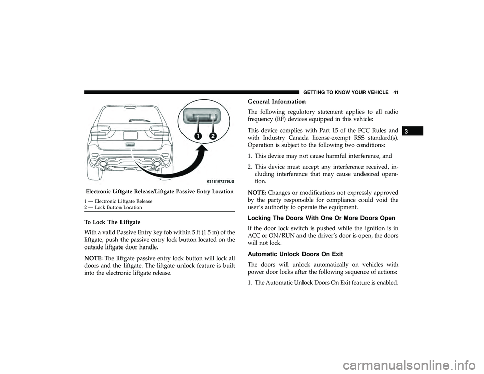
To Lock The Liftgate
With a valid Passive Entry key fob within 5 ft (1.5 m) of the
liftgate, push the passive entry lock button located on the
outside liftgate door handle.
NOTE:The liftgate passive entry lock button will lock all
doors and the liftgate. The liftgate unlock feature is built
into the electronic liftgate release.
General Information
The following regulatory statement applies to all radio
frequency (RF) devices equipped in this vehicle:
This device complies with Part 15 of the FCC Rules and
with Industry Canada license-exempt RSS standard(s).
Operation is subject to the following two conditions:
1. This device may not cause harmful interference, and
2. This device must accept any interference received, in- cluding interference that may cause undesired opera-
tion.
NOTE: Changes or modifications not expressly approved
by the party responsible for compliance could void the
user ’s authority to operate the equipment.
Locking The Doors With One Or More Doors Open
If the door lock switch is pushed while the ignition is in
ACC or ON/RUN and the driver’s door is open, the doors
will not lock.
Automatic Unlock Doors On Exit
The doors will unlock automatically on vehicles with
power door locks after the following sequence of actions:
1. The Automatic Unlock Doors On Exit feature is enabled.
Page 122 of 626
General Information
The following regulatory statement applies to all Radio
Frequency (RF) devices equipped in this vehicle:
This device complies with Part 15 of the FCC Rules and
with Innovation, Science and Economic Development
Canada license-exempt RSS standard(s). Operation is sub-
ject to the following two conditions:
1. This device may not cause harmful interference, and
2. This device must accept any interference received, in-cluding interference that may cause undesired opera-
tion.
NOTE: Changes or modifications not expressly approved
by the party responsible for compliance could void the
user ’s authority to operate the equipment.
INTERNAL EQUIPMENT
Storage
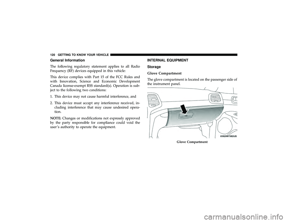
Glove Compartment
The glove compartment is located on the passenger side of
the instrument panel.
Page 134 of 626
CAUTION!(Continued)
•To avoid damage to the roof rack and vehicle, do not
exceed the maximum roof rack load capacity of 150 lb
(68 kg). Always distribute heavy loads as evenly as
possible and secure the load appropriately.
• Long loads which extend over the windshield, such
as wood panels or surfboards, or loads with large
frontal area should be secured to both the front and
rear of the vehicle.
• Place a blanket or other protection between the
surface of the roof and the load.
• Travel at reduced speeds and turn corners carefully
when carrying large or heavy loads on the roof rack.
Wind forces, due to natural causes or nearby truck
traffic, can add sudden upward lift to a load. This is
especially true on large flat loads and may result in
damage to the cargo or your vehicle.
• The use of Sport Mode is not recommended when
using the Roof Luggage Rack to carry a load.
132 GETTING TO KNOW YOUR VEHICLE
Page 159 of 626
CAUTION!
Do not continue driving with one or more flat tires as
handling may be compromised. Stop the vehicle,
avoiding sharp braking and steering. If a tire puncture
occurs, repair immediately using the dedicated tire
repair kit and contact an authorized dealer as soon as
possible.
Each tire, including the spare (if provided), should be
checked monthly when cold and inflated to the inflation
pressure recommended by the vehicle manufacturer on the
vehicle placard or tire inflation pressure label. (If your
vehicle has tires of a different size than the size indicated
on the vehicle placard or tire inflation pressure label, you
should determine the proper tire inflation pressure for
those tires.)
As an added safety feature, your vehicle has been
equipped with a Tire Pressure Monitoring System (TPMS)
that illuminates a low tire pressure telltale when one or
more of your tires is significantly under-inflated. Accord-
ingly, when the low tire pressure telltale illuminates, you
should stop and check your tires as soon as possible, and
inflate them to the proper pressure. Driving on a signifi-
cantly under-inflated tire causes the tire to overheat and can lead to tire failure. Under-inflation also reduces fuel
efficiency and tire tread life, and may affect the vehicle’s
handling and stopping ability.
Please note that the TPMS is not a substitute for proper tire
maintenance, and it is the driver ’s responsibility to main-
tain correct tire pressure, even if under-inflation has not
reached the level to trigger illumination of the TPMS low
tire pressure telltale.
Your vehicle has also been equipped with a TPMS malfunc-
tion indicator to indicate when the system is not operating
properly. The TPMS malfunction indicator is combined
with the low tire pressure telltale. When the system detects
a malfunction, the telltale will flash for approximately one
minute and then remain continuously illuminated. This
sequence will continue upon subsequent vehicle start-ups
as long as the malfunction exists. When the malfunction
indicator is illuminated, the system may not be able to
detect or signal low tire pressure as intended. TPMS
malfunctions may occur for a variety of reasons, including
the installation of replacement or alternate tires or wheels
on the vehicle that prevent the TPMS from functioning
properly. Always check the TPMS malfunction telltale after
replacing one or more tires or wheels on your vehicle to
ensure that the replacement or alternate tires and wheels
allow the TPMS to continue to function properly.
4
GETTING TO KNOW YOUR INSTRUMENT PANEL 157
Page 178 of 626
NOTE:The DST feature is only meant to help the driver
realize the correct course of action through small torques
on the steering wheel, which means the effectiveness of the
DST feature is highly dependent on the driver ’s sensitivity
and overall reaction to the applied torque. It is very
important to realize that this feature will not steer the
vehicle, meaning the driver is still responsible for steering
the vehicle.
Hill Descent Control (HDC) — If Equipped
HDC is intended for low speed off road driving while in
4WD Low Range. HDC maintains vehicle speed while
descending hills during various driving situations. HDC
controls vehicle speed by actively controlling the brakes.
HDC Has Three States:
1. Off (feature is not enabled and will not activate).
2. Enabled (feature is enabled and ready but activation conditions are not met, or driver is actively overriding
with brake or throttle application).
3. Active (feature is enabled and actively controlling ve- hicle speed). Enabling HDC
HDC is enabled by pushing the HDC switch, but the
following conditions must also be met to enable HDC:
•
Driveline is in 4WD Low Range.
• Vehicle speed is below 5 mph (8 km/h).
• Parking brake is released.
• Driver door is closed.
Activating HDC
Once HDC is enabled it will activate automatically if
driven down a grade of sufficient magnitude. The set speed
for HDC is selectable by the driver, and can be adjusted by
using the gear shift +/-. The following summarizes the
HDC set speeds:
HDC Target Set Speeds
• P = No set speed. HDC may be enabled but will not
activate.
• R = 0.6 mph (1 km/h)
• N = 1.2 mph (2 km/h)
176 SAFETY