wheel size JEEP GRAND CHEROKEE LIMITED 2019 Owners Manual
[x] Cancel search | Manufacturer: JEEP, Model Year: 2019, Model line: GRAND CHEROKEE LIMITED, Model: JEEP GRAND CHEROKEE LIMITED 2019Pages: 626, PDF Size: 3.77 MB
Page 159 of 626
CAUTION!
Do not continue driving with one or more flat tires as
handling may be compromised. Stop the vehicle,
avoiding sharp braking and steering. If a tire puncture
occurs, repair immediately using the dedicated tire
repair kit and contact an authorized dealer as soon as
possible.
Each tire, including the spare (if provided), should be
checked monthly when cold and inflated to the inflation
pressure recommended by the vehicle manufacturer on the
vehicle placard or tire inflation pressure label. (If your
vehicle has tires of a different size than the size indicated
on the vehicle placard or tire inflation pressure label, you
should determine the proper tire inflation pressure for
those tires.)
As an added safety feature, your vehicle has been
equipped with a Tire Pressure Monitoring System (TPMS)
that illuminates a low tire pressure telltale when one or
more of your tires is significantly under-inflated. Accord-
ingly, when the low tire pressure telltale illuminates, you
should stop and check your tires as soon as possible, and
inflate them to the proper pressure. Driving on a signifi-
cantly under-inflated tire causes the tire to overheat and can lead to tire failure. Under-inflation also reduces fuel
efficiency and tire tread life, and may affect the vehicle’s
handling and stopping ability.
Please note that the TPMS is not a substitute for proper tire
maintenance, and it is the driver ’s responsibility to main-
tain correct tire pressure, even if under-inflation has not
reached the level to trigger illumination of the TPMS low
tire pressure telltale.
Your vehicle has also been equipped with a TPMS malfunc-
tion indicator to indicate when the system is not operating
properly. The TPMS malfunction indicator is combined
with the low tire pressure telltale. When the system detects
a malfunction, the telltale will flash for approximately one
minute and then remain continuously illuminated. This
sequence will continue upon subsequent vehicle start-ups
as long as the malfunction exists. When the malfunction
indicator is illuminated, the system may not be able to
detect or signal low tire pressure as intended. TPMS
malfunctions may occur for a variety of reasons, including
the installation of replacement or alternate tires or wheels
on the vehicle that prevent the TPMS from functioning
properly. Always check the TPMS malfunction telltale after
replacing one or more tires or wheels on your vehicle to
ensure that the replacement or alternate tires and wheels
allow the TPMS to continue to function properly.
4
GETTING TO KNOW YOUR INSTRUMENT PANEL 157
Page 160 of 626
CAUTION!
The TPMS has been optimized for the original equip-
ment tires and wheels. TPMS pressures and warning
have been established for the tire size equipped on
your vehicle. Undesirable system operation or sensor
damage may result when using replacement equip-
ment that is not of the same size, type, and/or style.
Aftermarket wheels can cause sensor damage. Using
aftermarket tire sealants may cause the Tire Pressure
Monitoring System (TPMS) sensor to become inoper-
able. After using an aftermarket tire sealant it is
recommended that you take your vehicle to your au-
thorized dealer to have your sensor function checked.
Yellow Indicator Lights
Page 174 of 626
WARNING!
•Electronic Stability Control (ESC) cannot prevent the
natural laws of physics from acting on the vehicle,
nor can it increase the traction afforded by prevailing
road conditions. ESC cannot prevent accidents, in-
cluding those resulting from excessive speed in
turns, driving on very slippery surfaces, or hydro-
planing. ESC also cannot prevent accidents resulting
from loss of vehicle control due to inappropriate
driver input for the conditions. Only a safe, attentive,
and skillful driver can prevent accidents. The capa-
bilities of an ESC equipped vehicle must never be
exploited in a reckless or dangerous manner which
could jeopardize the user ’s safety or the safety of
others.
• Vehicle modifications, or failure to properly main-
tain your vehicle, may change the handling charac-
teristics of your vehicle, and may negatively affect
the performance of the ESC system. Changes to the
steering system, suspension, braking system, tire
type and size or wheel size may adversely affect ESC
performance. Improperly inflated and unevenly
worn tires may also degrade ESC performance. Any
(Continued)
Page 218 of 626
Front Air Bag Operation
Front Air Bags are designed to provide additional protec-
tion by supplementing the seat belts. Front air bags are not
expected to reduce the risk of injury in rear, side, or
rollover collisions. The front air bags will not deploy in all
frontal collisions, including some that may produce sub-
stantial vehicle damage — for example, some pole colli-
sions, truck underrides, and angle offset collisions.
On the other hand, depending on the type and location of
impact, front air bags may deploy in crashes with little
vehicle front-end damage but that produce a severe initial
deceleration.
Because air bag sensors measure vehicle deceleration over
time, vehicle speed and damage by themselves are not
good indicators of whether or not an air bag should have
deployed.
Seat belts are necessary for your protection in all collisions,
and also are needed to help keep you in position, away
from an inflating air bag.
When the ORC detects a collision requiring the front air
bags, it signals the inflator units. A large quantity of
non-toxic gas is generated to inflate the front air bags.The steering wheel hub trim cover and the upper passen-
ger side of the instrument panel separate and fold out of
the way as the air bags inflate to their full size. The front air
bags fully inflate in less time than it takes to blink your
eyes. The front air bags then quickly deflate while helping
to restrain the driver and front passenger.
Knee Impact Bolsters
The Knee Impact Bolsters help protect the knees of the
driver and front passenger, and position the front occu-
pants for improved interaction with the front air bags.
Page 275 of 626
FOUR WHEEL DRIVE OPERATION
Quadra-Trac I Operating Instructions/Precautions
— If Equipped
The Quadra-Trac I is a single-speed (HI range only) trans-
fer case, which provides convenient full-time four-wheel
drive. No driver interaction is required. The Brake Traction
Control (BTC) System, which combines standard ABS and
Traction Control, provides resistance to any wheel that is
slipping to allow additional torque transfer to wheels with
traction.
NOTE:The Quadra-Trac I system is not appropriate for
conditions where 4WD LOW range is recommended. Refer
to “Off-Road Driving Tips” in “Starting And Operating”
Quadra-Trac II Operating Instructions/Precautions
— If Equipped
The Quadra-Trac II transfer case is fully automatic in the
normal driving 4WD AUTO mode. The Quadra-Trac II
transfer case provides three mode positions:
• 4WD HI
• NEUTRAL
• 4WD LOW This transfer case is fully automatic in the 4WD HI mode.
When additional traction is required, the 4WD LOW
position can be used to lock the front and rear driveshafts
together and force the front and rear wheels to rotate at the
same speed. The 4WD LOW position is intended for loose,
slippery road surfaces only. Driving in the 4WD LOW
position on dry, hard-surfaced roads may cause increased
tire wear and damage to driveline components.
When operating your vehicle in 4WD LOW, the engine
speed is approximately three times that of the 4WD HI
position at a given road speed. Take care not to overspeed
the engine and do not exceed 25 mph (40 km/h).
Proper operation of four-wheel drive vehicles depends on
tires of equal size, type, and circumference on each wheel.
Any difference will adversely affect shifting and cause
damage to the transfer case.
Because four-wheel drive provides improved traction,
there is a tendency to exceed safe turning and stopping
speeds. Do not go faster than road conditions permit.
6
STARTING AND OPERATING 273
Page 297 of 626
WARNING!(Continued)
•Will bring the vehicle to a complete stop while
following a target vehicle and hold the vehicle for
2 seconds in the stop position. If the target vehicle
does not start moving within two seconds the ACC
system will display a message that the system will
release the brakes and that the brakes must be
applied manually. An audible chime will sound
when the brakes are released.
You should switch off the ACC system:
• When driving in fog, heavy rain, heavy snow, sleet,
heavy traffic, and complex driving situations (i.e., in
highway construction zones).
• When entering a turn lane or highway off ramp;
when driving on roads that are winding, icy, snow-
covered, slippery, or have steep uphill or downhill
slopes.
• When towing a trailer up or down steep slopes.
• When circumstances do not allow safe driving at a
constant speed.
Adaptive Cruise Control (ACC) Operation
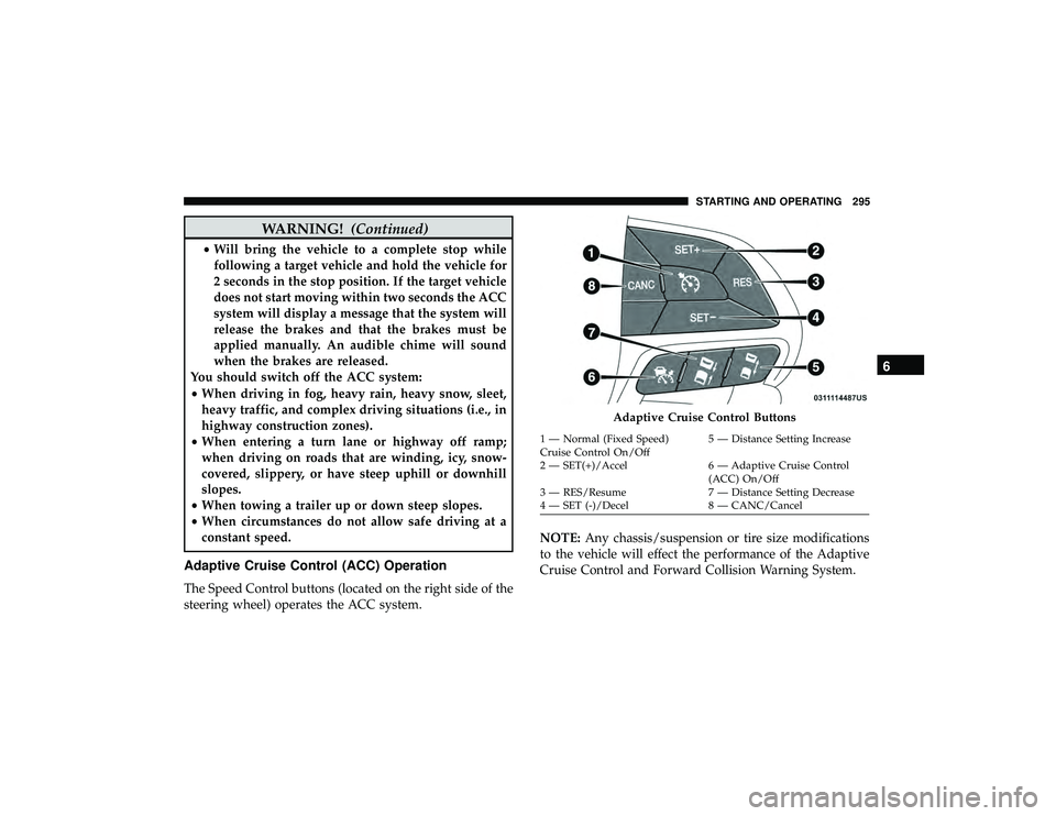
The Speed Control buttons (located on the right side of the
steering wheel) operates the ACC system. NOTE:
Any chassis/suspension or tire size modifications
to the vehicle will effect the performance of the Adaptive
Cruise Control and Forward Collision Warning System.
Page 364 of 626
NOTE:If the fuel door does not latch after the manual
release cable has been activated, the actuator latch should
be manually returned to the closed position.
VEHICLE LOADING
Certification Label
As required by National Highway Traffic Safety Adminis-
tration regulations, your vehicle has a certification label
affixed to the driver’s side door or pillar.
This label contains the month and year of manufacture,
Gross Vehicle Weight Rating (GVWR), Gross Axle Weight
Rating (GAWR) front and rear, and Vehicle Identification
Number (VIN). A Month-Day-Hour (MDH) number is
included on this label and indicates the Month, Day and
Hour of manufacture. The bar code that appears on the
bottom of the label is your VIN.
Gross Vehicle Weight Rating (GVWR)
The GVWR is the total permissible weight of your vehicle
including driver, passengers, vehicle, options and cargo.
The label also specifies maximum capacities of front and
rear axle systems (GAWR). Total load must be limited so
GVWR and front and rear GAWR are not exceeded.
Payload
The payload of a vehicle is defined as the allowable load
weight a truck can carry, including the weight of the driver,
all passengers, options and cargo.
Gross Axle Weight Rating (GAWR)
The GAWR is the maximum permissible load on the front
and rear axles. The load must be distributed in the cargo
area so that the GAWR of each axle is not exceeded.
Each axle GAWR is determined by the components in the
system with the lowest load carrying capacity (axle,
springs, tires or wheels). Heavier axles or suspension
components sometimes specified by purchasers for in-
creased durability does not necessarily increase the vehi-
cle’s GVWR.
Tire Size
The tire size on the Vehicle Certification Label represents
the actual tire size on your vehicle. Replacement tires must
be equal to the load capacity of this tire size.
362 STARTING AND OPERATING
Page 490 of 626
When cleaning extremely dirty wheels including excessive
brake dust, care must be taken in the selection of tire and
wheel cleaning chemicals and equipment to prevent dam-
age to the wheels. Mopar Wheel Treatment or Mopar
Chrome Cleaner or their equivalent is recommended or
select a non-abrasive, non-acidic cleaner for aluminum or
chrome wheels.
CAUTION!
If your vehicle is equipped with these specialty
wheels, DO NOT USE wheel cleaners, abrasives, or
polishing compounds. They will permanently damage
this finish and such damage is not covered by the New
Vehicle Limited Warranty. HAND WASH ONLY US-
ING MILD SOAP AND WATER WITH A SOFT
CLOTH. Used on a regular basis; this is all that is
required to maintain this finish.
Tire Chains (Traction Devices)
Use of traction devices require sufficient tire-to-body clear-
ance. Follow these recommendations to guard against
damage.
•Traction device must be of proper size for the tire, as
recommended by the traction device manufacturer.
• Install on Rear Tires Only
• Due to limited clearance, Thule XG-12 Pro or equivalent
is recommended on P245/70R17, 265/60R18 or 265/
50R20 tires.
488 SERVICING AND MAINTENANCE
Page 623 of 626
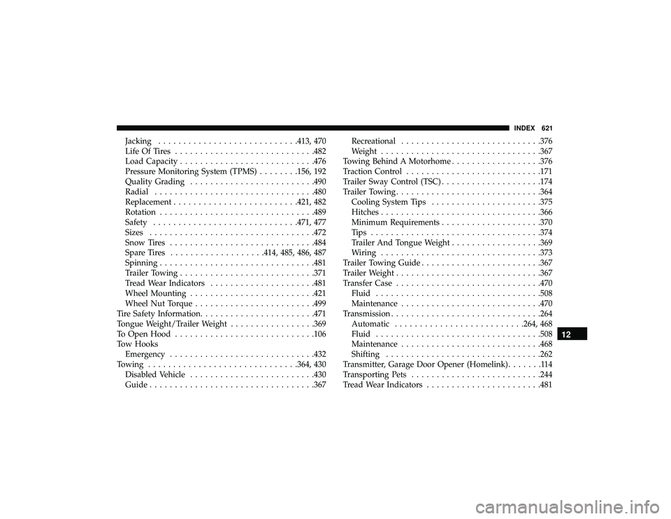
Jacking........................... .413, 470
Life Of Tires ........................... .482
Load Capacity .......................... .476
Pressure Monitoring System (TPMS) ........156, 192
Quality Grading ........................ .490
Radial ............................... .480
Replacement ........................ .421, 482
Rotation .............................. .489
Safety ............................ .471, 477
Sizes ................................ .472
Snow Tires ............................ .484
Spare Tires .................. .414, 485, 486, 487
Spinning .............................. .481
Trailer Towing .......................... .371
Tread Wear Indicators .....................481
Wheel Mounting ........................ .421
Wheel Nut Torque ....................... .499
Tire Safety Information .......................471
Tongue Weight/Trailer Weight .................369
To Open Hood ........................... .106
Tow Hooks Emergency ............................ .432
Towing ............................. .364, 430
Disabled Vehicle ........................ .430
Guide ................................ .367Recreational
........................... .376
Weight ............................... .367
Towing Behind A Motorhome ..................376
Traction Control .......................... .171
Trailer Sway Control (TSC) ....................174
Trailer Towing ............................ .364
Cooling System Tips ..................... .375
Hitches ............................... .366
Minimum Requirements ................... .370
Tips ................................. .374
T railer
And Tongue Weight ..................369
Wiring ............................... .373
Trailer Towing Guide ....................... .367
Trailer Weight ............................ .367
Transfer Case ............................ .470
Fluid ................................ .508
Maintenance ........................... .470
Transmission ............................. .264
Automatic ......................... .264, 468
Fluid ................................ .508
Maintenance ........................... .468
Shifting .............................. .262
Transmitter, Garage Door Opener (Homelink) .......114
Transporting Pets ......................... .244
Tread Wear Indicators .......................481
12
INDEX 621