warning light JEEP LIBERTY 2002 KJ / 1.G Owners Manual
[x] Cancel search | Manufacturer: JEEP, Model Year: 2002, Model line: LIBERTY, Model: JEEP LIBERTY 2002 KJ / 1.GPages: 1803, PDF Size: 62.3 MB
Page 587 of 1803
TRAILER TOW RELAY
DESCRIPTION
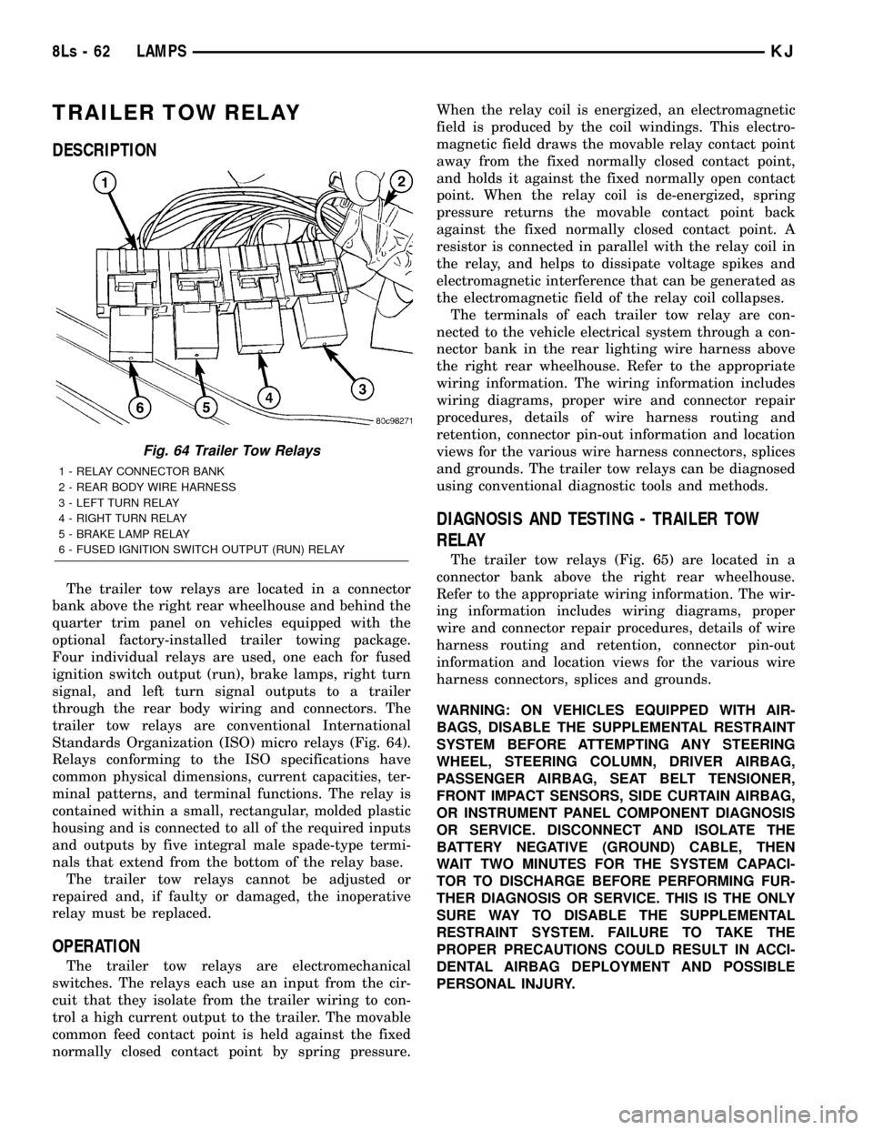
The trailer tow relays are located in a connector
bank above the right rear wheelhouse and behind the
quarter trim panel on vehicles equipped with the
optional factory-installed trailer towing package.
Four individual relays are used, one each for fused
ignition switch output (run), brake lamps, right turn
signal, and left turn signal outputs to a trailer
through the rear body wiring and connectors. The
trailer tow relays are conventional International
Standards Organization (ISO) micro relays (Fig. 64).
Relays conforming to the ISO specifications have
common physical dimensions, current capacities, ter-
minal patterns, and terminal functions. The relay is
contained within a small, rectangular, molded plastic
housing and is connected to all of the required inputs
and outputs by five integral male spade-type termi-
nals that extend from the bottom of the relay base.
The trailer tow relays cannot be adjusted or
repaired and, if faulty or damaged, the inoperative
relay must be replaced.
OPERATION
The trailer tow relays are electromechanical
switches. The relays each use an input from the cir-
cuit that they isolate from the trailer wiring to con-
trol a high current output to the trailer. The movable
common feed contact point is held against the fixed
normally closed contact point by spring pressure.When the relay coil is energized, an electromagnetic
field is produced by the coil windings. This electro-
magnetic field draws the movable relay contact point
away from the fixed normally closed contact point,
and holds it against the fixed normally open contact
point. When the relay coil is de-energized, spring
pressure returns the movable contact point back
against the fixed normally closed contact point. A
resistor is connected in parallel with the relay coil in
the relay, and helps to dissipate voltage spikes and
electromagnetic interference that can be generated as
the electromagnetic field of the relay coil collapses.
The terminals of each trailer tow relay are con-
nected to the vehicle electrical system through a con-
nector bank in the rear lighting wire harness above
the right rear wheelhouse. Refer to the appropriate
wiring information. The wiring information includes
wiring diagrams, proper wire and connector repair
procedures, details of wire harness routing and
retention, connector pin-out information and location
views for the various wire harness connectors, splices
and grounds. The trailer tow relays can be diagnosed
using conventional diagnostic tools and methods.
DIAGNOSIS AND TESTING - TRAILER TOW
RELAY
The trailer tow relays (Fig. 65) are located in a
connector bank above the right rear wheelhouse.
Refer to the appropriate wiring information. The wir-
ing information includes wiring diagrams, proper
wire and connector repair procedures, details of wire
harness routing and retention, connector pin-out
information and location views for the various wire
harness connectors, splices and grounds.
WARNING: ON VEHICLES EQUIPPED WITH AIR-
BAGS, DISABLE THE SUPPLEMENTAL RESTRAINT
SYSTEM BEFORE ATTEMPTING ANY STEERING
WHEEL, STEERING COLUMN, DRIVER AIRBAG,
PASSENGER AIRBAG, SEAT BELT TENSIONER,
FRONT IMPACT SENSORS, SIDE CURTAIN AIRBAG,
OR INSTRUMENT PANEL COMPONENT DIAGNOSIS
OR SERVICE. DISCONNECT AND ISOLATE THE
BATTERY NEGATIVE (GROUND) CABLE, THEN
WAIT TWO MINUTES FOR THE SYSTEM CAPACI-
TOR TO DISCHARGE BEFORE PERFORMING FUR-
THER DIAGNOSIS OR SERVICE. THIS IS THE ONLY
SURE WAY TO DISABLE THE SUPPLEMENTAL
RESTRAINT SYSTEM. FAILURE TO TAKE THE
PROPER PRECAUTIONS COULD RESULT IN ACCI-
DENTAL AIRBAG DEPLOYMENT AND POSSIBLE
PERSONAL INJURY.
Fig. 64 Trailer Tow Relays
1 - RELAY CONNECTOR BANK
2 - REAR BODY WIRE HARNESS
3 - LEFT TURN RELAY
4 - RIGHT TURN RELAY
5 - BRAKE LAMP RELAY
6 - FUSED IGNITION SWITCH OUTPUT (RUN) RELAY
8Ls - 62 LAMPSKJ
Page 588 of 1803
(1) Remove the trailer tow relay from the connec-
tor bank. (Refer to 8 - ELECTRICAL/LAMPS/LIGHT-
ING - EXTERIOR/TRAILER TOW RELAY -
REMOVAL).
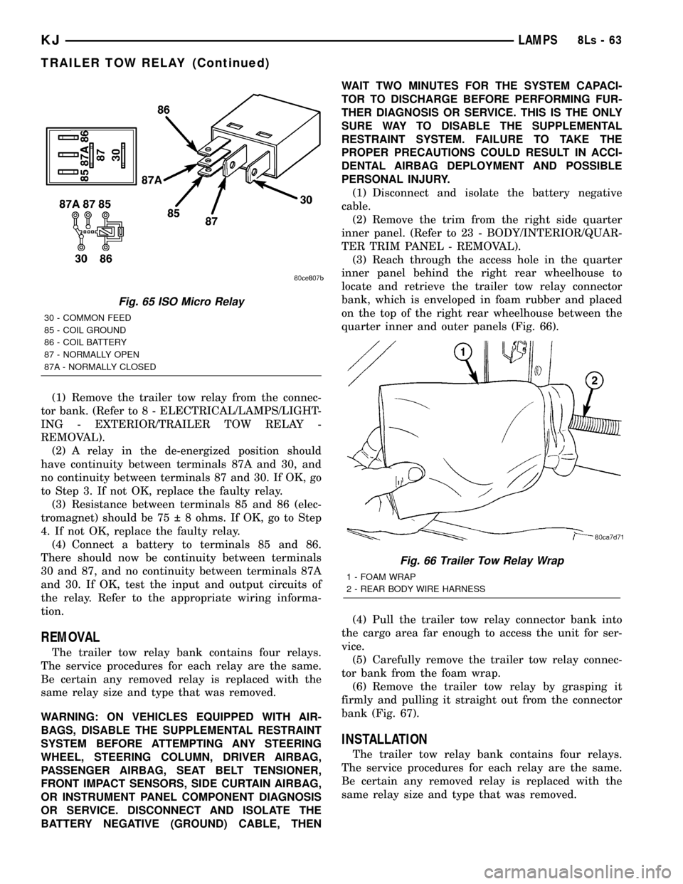
(2) A relay in the de-energized position should
have continuity between terminals 87A and 30, and
no continuity between terminals 87 and 30. If OK, go
to Step 3. If not OK, replace the faulty relay.
(3) Resistance between terminals 85 and 86 (elec-
tromagnet) should be 75 8 ohms. If OK, go to Step
4. If not OK, replace the faulty relay.
(4) Connect a battery to terminals 85 and 86.
There should now be continuity between terminals
30 and 87, and no continuity between terminals 87A
and 30. If OK, test the input and output circuits of
the relay. Refer to the appropriate wiring informa-
tion.
REMOVAL
The trailer tow relay bank contains four relays.
The service procedures for each relay are the same.
Be certain any removed relay is replaced with the
same relay size and type that was removed.
WARNING: ON VEHICLES EQUIPPED WITH AIR-
BAGS, DISABLE THE SUPPLEMENTAL RESTRAINT
SYSTEM BEFORE ATTEMPTING ANY STEERING
WHEEL, STEERING COLUMN, DRIVER AIRBAG,
PASSENGER AIRBAG, SEAT BELT TENSIONER,
FRONT IMPACT SENSORS, SIDE CURTAIN AIRBAG,
OR INSTRUMENT PANEL COMPONENT DIAGNOSIS
OR SERVICE. DISCONNECT AND ISOLATE THE
BATTERY NEGATIVE (GROUND) CABLE, THENWAIT TWO MINUTES FOR THE SYSTEM CAPACI-
TOR TO DISCHARGE BEFORE PERFORMING FUR-
THER DIAGNOSIS OR SERVICE. THIS IS THE ONLY
SURE WAY TO DISABLE THE SUPPLEMENTAL
RESTRAINT SYSTEM. FAILURE TO TAKE THE
PROPER PRECAUTIONS COULD RESULT IN ACCI-
DENTAL AIRBAG DEPLOYMENT AND POSSIBLE
PERSONAL INJURY.
(1) Disconnect and isolate the battery negative
cable.
(2) Remove the trim from the right side quarter
inner panel. (Refer to 23 - BODY/INTERIOR/QUAR-
TER TRIM PANEL - REMOVAL).
(3) Reach through the access hole in the quarter
inner panel behind the right rear wheelhouse to
locate and retrieve the trailer tow relay connector
bank, which is enveloped in foam rubber and placed
on the top of the right rear wheelhouse between the
quarter inner and outer panels (Fig. 66).
(4) Pull the trailer tow relay connector bank into
the cargo area far enough to access the unit for ser-
vice.
(5) Carefully remove the trailer tow relay connec-
tor bank from the foam wrap.
(6) Remove the trailer tow relay by grasping it
firmly and pulling it straight out from the connector
bank (Fig. 67).
INSTALLATION
The trailer tow relay bank contains four relays.
The service procedures for each relay are the same.
Be certain any removed relay is replaced with the
same relay size and type that was removed.
Fig. 65 ISO Micro Relay
30 - COMMON FEED
85 - COIL GROUND
86 - COIL BATTERY
87 - NORMALLY OPEN
87A - NORMALLY CLOSED
Fig. 66 Trailer Tow Relay Wrap
1 - FOAM WRAP
2 - REAR BODY WIRE HARNESS
KJLAMPS8Ls-63
TRAILER TOW RELAY (Continued)
Page 589 of 1803
WARNING: ON VEHICLES EQUIPPED WITH AIR-
BAGS, DISABLE THE SUPPLEMENTAL RESTRAINT
SYSTEM BEFORE ATTEMPTING ANY STEERING
WHEEL, STEERING COLUMN, DRIVER AIRBAG,
PASSENGER AIRBAG, SEAT BELT TENSIONER,
FRONT IMPACT SENSORS, SIDE CURTAIN AIRBAG,
OR INSTRUMENT PANEL COMPONENT DIAGNOSIS
OR SERVICE. DISCONNECT AND ISOLATE THE
BATTERY NEGATIVE (GROUND) CABLE, THEN
WAIT TWO MINUTES FOR THE SYSTEM CAPACI-
TOR TO DISCHARGE BEFORE PERFORMING FUR-
THER DIAGNOSIS OR SERVICE. THIS IS THE ONLY
SURE WAY TO DISABLE THE SUPPLEMENTAL
RESTRAINT SYSTEM. FAILURE TO TAKE THE
PROPER PRECAUTIONS COULD RESULT IN ACCI-
DENTAL AIRBAG DEPLOYMENT AND POSSIBLE
PERSONAL INJURY.
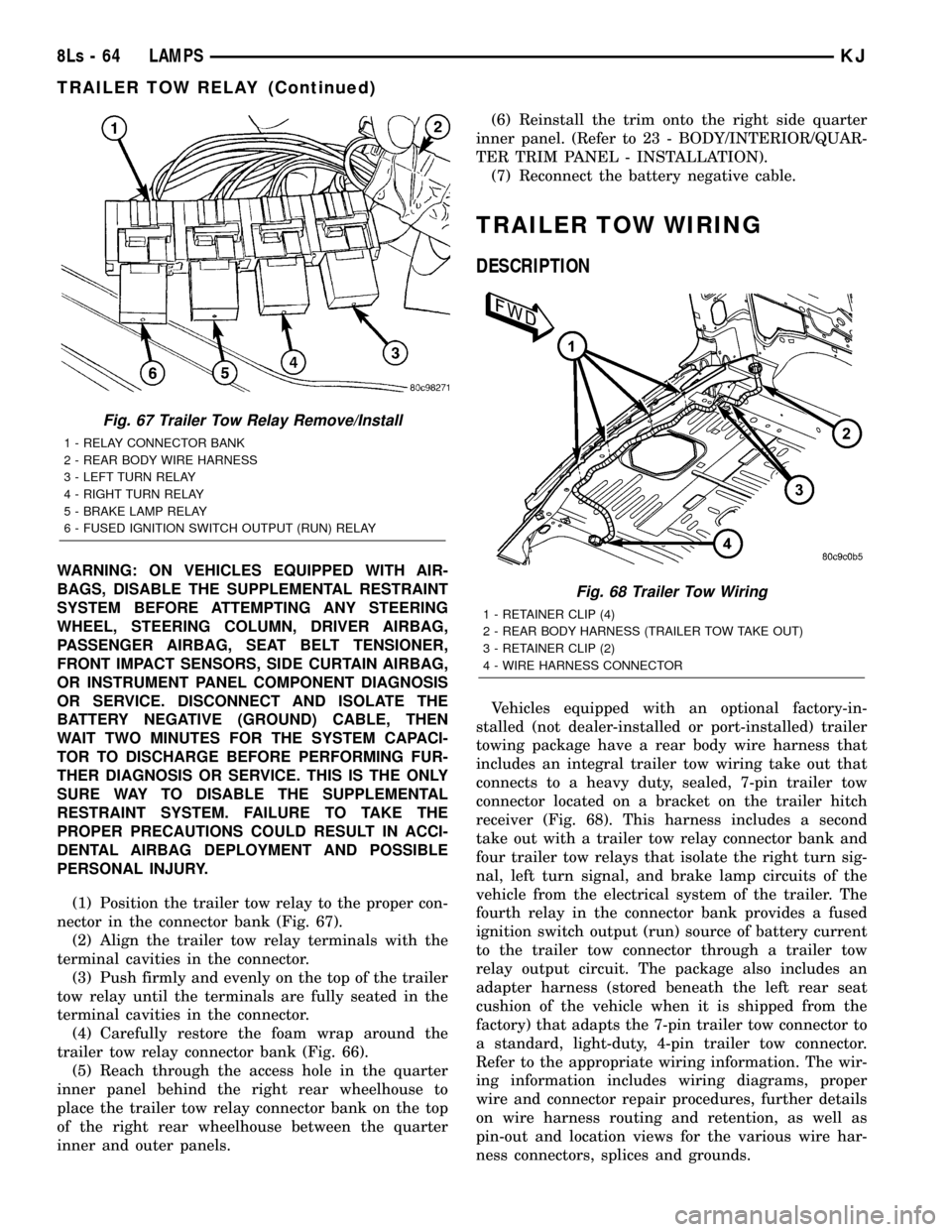
(1) Position the trailer tow relay to the proper con-
nector in the connector bank (Fig. 67).
(2) Align the trailer tow relay terminals with the
terminal cavities in the connector.
(3) Push firmly and evenly on the top of the trailer
tow relay until the terminals are fully seated in the
terminal cavities in the connector.
(4) Carefully restore the foam wrap around the
trailer tow relay connector bank (Fig. 66).
(5) Reach through the access hole in the quarter
inner panel behind the right rear wheelhouse to
place the trailer tow relay connector bank on the top
of the right rear wheelhouse between the quarter
inner and outer panels.(6) Reinstall the trim onto the right side quarter
inner panel. (Refer to 23 - BODY/INTERIOR/QUAR-
TER TRIM PANEL - INSTALLATION).
(7) Reconnect the battery negative cable.
TRAILER TOW WIRING
DESCRIPTION
Vehicles equipped with an optional factory-in-
stalled (not dealer-installed or port-installed) trailer
towing package have a rear body wire harness that
includes an integral trailer tow wiring take out that
connects to a heavy duty, sealed, 7-pin trailer tow
connector located on a bracket on the trailer hitch
receiver (Fig. 68). This harness includes a second
take out with a trailer tow relay connector bank and
four trailer tow relays that isolate the right turn sig-
nal, left turn signal, and brake lamp circuits of the
vehicle from the electrical system of the trailer. The
fourth relay in the connector bank provides a fused
ignition switch output (run) source of battery current
to the trailer tow connector through a trailer tow
relay output circuit. The package also includes an
adapter harness (stored beneath the left rear seat
cushion of the vehicle when it is shipped from the
factory) that adapts the 7-pin trailer tow connector to
a standard, light-duty, 4-pin trailer tow connector.
Refer to the appropriate wiring information. The wir-
ing information includes wiring diagrams, proper
wire and connector repair procedures, further details
on wire harness routing and retention, as well as
pin-out and location views for the various wire har-
ness connectors, splices and grounds.
Fig. 67 Trailer Tow Relay Remove/Install
1 - RELAY CONNECTOR BANK
2 - REAR BODY WIRE HARNESS
3 - LEFT TURN RELAY
4 - RIGHT TURN RELAY
5 - BRAKE LAMP RELAY
6 - FUSED IGNITION SWITCH OUTPUT (RUN) RELAY
Fig. 68 Trailer Tow Wiring
1 - RETAINER CLIP (4)
2 - REAR BODY HARNESS (TRAILER TOW TAKE OUT)
3 - RETAINER CLIP (2)
4 - WIRE HARNESS CONNECTOR
8Ls - 64 LAMPSKJ
TRAILER TOW RELAY (Continued)
Page 659 of 1803
REAR CENTER SEAT BELT &
RETRACTOR
REMOVAL
WARNING: DURING AND FOLLOWING ANY SEAT
BELT SERVICE, CAREFULLY INSPECT ALL SEAT
BELTS, BUCKLES, MOUNTING HARDWARE, AND
RETRACTORS FOR PROPER INSTALLATION,
OPERATION, OR DAMAGE. REPLACE ANY BELT
THAT IS CUT, FRAYED, OR TORN. STRAIGHTEN
ANY BELT THAT IS TWISTED. TIGHTEN ANY
LOOSE FASTENERS. REPLACE ANY BELT THAT
HAS A DAMAGED OR INOPERATIVE BUCKLE OR
RETRACTOR. REPLACE ANY BELT THAT HAS A
BENT OR DAMAGED LATCH PLATE OR ANCHOR
PLATE. NEVER ATTEMPT TO REPAIR A SEAT BELT
COMPONENT. ALWAYS REPLACE DAMAGED OR
FAULTY SEAT BELT COMPONENTS WITH THE COR-
RECT, NEW AND UNUSED REPLACEMENT PARTS
LISTED IN THE MOPAR PARTS CATALOG.
(1) Remove the right center seat belt buckle unit
from the floor panel. (Refer to 8 - ELECTRICAL/RE-
STRAINTS/REAR SEAT BELT BUCKLE - REMOV-
AL).
(2) Unlatch and fold the right rear seat back for-
ward and separate the cargo area carpet from the
base of the seat back panel.
(3) Reach between the base of the right rear seat
back and the forward edge of the rear cargo floor to
access and remove the screw that secures the rear
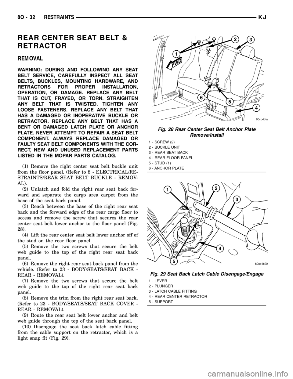
center seat belt lower anchor to the floor panel (Fig.
28).
(4) Lift the rear center seat belt lower anchor off of
the stud on the rear floor panel.
(5) Remove the two screws that secure the belt
web guide to the top of the right rear seat back
panel.
(6) Remove the right rear seat back panel from the
vehicle. (Refer to 23 - BODY/SEATS/SEAT BACK -
REAR - REMOVAL).
(7) Remove the two screws that secure the belt
web guide to the top of the right rear seat back
panel.
(8) Remove the trim from the right rear seat back.
(Refer to 23 - BODY/SEATS/SEAT BACK COVER -
REAR - REMOVAL).
(9) Route the rear seat belt lower anchor and belt
web guide through the top of the seat back panel.
(10) Disengage the seat back latch cable fitting
from the cable support on the retractor, which is a
light snap fit (Fig. 29).
Fig. 28 Rear Center Seat Belt Anchor Plate
Remove/Install
1 - SCREW (2)
2 - BUCKLE UNIT
3 - REAR SEAT BACK
4 - REAR FLOOR PANEL
5 - STUD (1)
6 - ANCHOR PLATE
Fig. 29 Seat Back Latch Cable Disengage/Engage
1 - LEVER
2 - PLUNGER
3 - LATCH CABLE FITTING
4 - REAR CENTER RETRACTOR
5 - SUPPORT
8O - 32 RESTRAINTSKJ
Page 660 of 1803
(11) Remove the screw that secures the retractor
to the rear seat back panel (Fig. 30).
(12) Remove the rear center seat belt and retractor
unit from the seat back panel.
INSTALLATION
WARNING: DURING AND FOLLOWING ANY SEAT
BELT SERVICE, CAREFULLY INSPECT ALL SEAT
BELTS, BUCKLES, MOUNTING HARDWARE, AND
RETRACTORS FOR PROPER INSTALLATION,
OPERATION, OR DAMAGE. REPLACE ANY BELT
THAT IS CUT, FRAYED, OR TORN. STRAIGHTEN
ANY BELT THAT IS TWISTED. TIGHTEN ANY
LOOSE FASTENERS. REPLACE ANY BELT THAT
HAS A DAMAGED OR INOPERATIVE BUCKLE OR
RETRACTOR. REPLACE ANY BELT THAT HAS A
BENT OR DAMAGED LATCH PLATE OR ANCHOR
PLATE. NEVER ATTEMPT TO REPAIR A SEAT BELT
COMPONENT. ALWAYS REPLACE DAMAGED OR
FAULTY SEAT BELT COMPONENTS WITH THE COR-
RECT, NEW AND UNUSED REPLACEMENT PARTS
LISTED IN THE MOPAR PARTS CATALOG.
(1) Position the rear center seat belt and retractor
unit onto the seat back panel.
(2) Install and tighten the screw that secures the
retractor to the rear seat back panel (Fig. 30).
Tighten the screw to 27 N´m (20 ft. lbs.).
(3) Position the seat back latch cable plunger
against the retractor latch lever, then engage the
cable fitting into the cable support on the retractor,
which is a light snap fit (Fig. 29).
(4) Route the rear seat belt lower anchor and belt
web guide through the top of the seat back panel.(5) Reinstall the trim onto the right rear seat
back. (Refer to 23 - BODY/SEATS/SEAT BACK
COVER - REAR - INSTALLATION).
(6) Install and tighten the two screws that secure
the belt web guide to the top of the right rear seat
back panel. Tighten the screws to 2 N´m (20 in. lbs.).
(7) Reinstall the right rear seat back panel into
the vehicle. (Refer to 23 - BODY/SEATS/SEAT BACK
- REAR - INSTALLATION).
(8) Position the rear center seat belt lower anchor
off of the stud on the rear floor panel (Fig. 28).
(9) Reach between the base of the right rear seat
back and the forward edge of the rear cargo floor to
install and tighten the screw that secures the rear
center seat belt lower anchor to the floor panel.
Tighten the screw to 43 N´m (32 ft. lbs.).
(10) Restore the cargo area carpet to the base of
the seat back panel and unfold the right rear seat
back to its upright position.
(11) Reinstall the right center seat belt buckle unit
onto the floor panel. (Refer to 8 - ELECTRICAL/RE-
STRAINTS/SEAT BELT BUCKLE - INSTALLA-
TION).
REAR OUTBOARD SEAT BELT
& RETRACTOR
REMOVAL
WARNING: DURING AND FOLLOWING ANY SEAT
BELT SERVICE, CAREFULLY INSPECT ALL SEAT
BELTS, BUCKLES, MOUNTING HARDWARE, AND
RETRACTORS FOR PROPER INSTALLATION,
OPERATION, OR DAMAGE. REPLACE ANY BELT
THAT IS CUT, FRAYED, OR TORN. STRAIGHTEN
ANY BELT THAT IS TWISTED. TIGHTEN ANY
LOOSE FASTENERS. REPLACE ANY BELT THAT
HAS A DAMAGED OR INOPERATIVE BUCKLE OR
RETRACTOR. REPLACE ANY BELT THAT HAS A
BENT OR DAMAGED LATCH PLATE OR ANCHOR
PLATE. NEVER ATTEMPT TO REPAIR A SEAT BELT
COMPONENT. ALWAYS REPLACE DAMAGED OR
FAULTY SEAT BELT COMPONENTS WITH THE COR-
RECT, NEW AND UNUSED REPLACEMENT PARTS
LISTED IN THE MOPAR PARTS CATALOG.
(1) Unsnap and lift the trim cover to access the
screw that secures the rear outboard seat belt turn-
ing loop to the upper C-pillar (Fig. 31).
(2) Remove the screw that secures the seat belt
turning loop to the upper C-pillar.
(3) Remove the screw that secures the lower seat
belt anchor to the bracket on the outboard side of the
rear seat cushion frame.
Fig. 30 Rear Center Retractor Remove/Install
1 - REAR SEAT BACK PANEL
2 - SCREW (1)
KJRESTRAINTS 8O - 33
REAR CENTER SEAT BELT & RETRACTOR (Continued)
Page 707 of 1803
cycles that occur after the front Wash switch state
changes to open, and to determine the proper inter-
val at which to de-energize the wiper on/off relay to
complete the wipe-after-wash mode cycle.
DIAGNOSIS AND TESTING - FRONT WIPER &
WASHER SYSTEM
FRONT WIPER SYSTEM
If the front wiper motor operates, but the wipers
do not move on the windshield, replace the faulty
front wiper module. If the wipers operate, but chat-
ter, lift, or do not clear the glass, clean and inspect
the front wiper system components as required.
(Refer to 8 - ELECTRICAL/FRONT WIPERS/WASH-
ERS - INSPECTION) and (Refer to 8 - ELECTRI-
CAL/FRONT WIPERS/WASHERS - CLEANING). For
diagnosis and testing of the multi-function switch
(Refer to 8 - ELECTRICAL/LAMPS/LIGHTING -
EXTERIOR/MULTI-FUNCTION SWITCH - DIAG-
NOSIS AND TESTING). Refer to the appropriate
wiring information. The wiring information includes
wiring diagrams, proper wire and connector repair
procedures, details of wire harness routing and
retention, connector pin-out information and location
views for the various wire harness connectors, splices
and grounds.
The hard wired circuits and components of the
front wiper and washer system may be diagnosed
and tested using conventional diagnostic tools and
procedures. However, conventional diagnostic meth-
ods may not prove conclusive in the diagnosis of the
Body Control Module (BCM), or the inputs to or out-
puts from the BCM that control the various front
wiper and washer system operating modes. The most
reliable, efficient, and accurate means to diagnose
the BCM, or the BCM inputs and outputs related to
the various front wiper and washer system operating
modes requires the use of a DRBIIItscan tool. Refer
to the appropriate diagnostic information.
WARNING: ON VEHICLES EQUIPPED WITH AIR-
BAGS, DISABLE THE SUPPLEMENTAL RESTRAINT
SYSTEM BEFORE ATTEMPTING ANY STEERING
WHEEL, STEERING COLUMN, DRIVER AIRBAG,
PASSENGER AIRBAG, SEAT BELT TENSIONER,
SIDE CURTAIN AIRBAG, OR INSTRUMENT PANEL
COMPONENT DIAGNOSIS OR SERVICE. DISCON-
NECT AND ISOLATE THE BATTERY NEGATIVE
(GROUND) CABLE, THEN WAIT TWO MINUTES FOR
THE SYSTEM CAPACITOR TO DISCHARGE BEFORE
PERFORMING FURTHER DIAGNOSIS OR SERVICE.
THIS IS THE ONLY SURE WAY TO DISABLE THE
SUPPLEMENTAL RESTRAINT SYSTEM. FAILURE TO
TAKE THE PROPER PRECAUTIONS COULDRESULT IN ACCIDENTAL AIRBAG DEPLOYMENT
AND POSSIBLE PERSONAL INJURY.
FRONT WASHER SYSTEM
The diagnosis found here addresses an electrically
inoperative front washer system. If the washer
pump/motor operates, but no washer fluid is emitted
from the front washer nozzles, be certain to check
the fluid level in the reservoir. Also inspect the front
washer system components as required. (Refer to 8 -
ELECTRICAL/FRONT WIPERS/WASHERS -
INSPECTION). Refer to the appropriate wiring infor-
mation. The wiring information includes wiring dia-
grams, proper wire and connector repair procedures,
details of wire harness routing and retention, connec-
tor pin-out information and location views for the
various wire harness connectors, splices and grounds.
WARNING: ON VEHICLES EQUIPPED WITH AIR-
BAGS, DISABLE THE SUPPLEMENTAL RESTRAINT
SYSTEM BEFORE ATTEMPTING ANY STEERING
WHEEL, STEERING COLUMN, DRIVER AIRBAG,
PASSENGER AIRBAG, SEAT BELT TENSIONER,
SIDE CURTAIN AIRBAG, OR INSTRUMENT PANEL
COMPONENT DIAGNOSIS OR SERVICE. DISCON-
NECT AND ISOLATE THE BATTERY NEGATIVE
(GROUND) CABLE, THEN WAIT TWO MINUTES FOR
THE SYSTEM CAPACITOR TO DISCHARGE BEFORE
PERFORMING FURTHER DIAGNOSIS OR SERVICE.
THIS IS THE ONLY SURE WAY TO DISABLE THE
SUPPLEMENTAL RESTRAINT SYSTEM. FAILURE TO
TAKE THE PROPER PRECAUTIONS COULD
RESULT IN ACCIDENTAL AIRBAG DEPLOYMENT
AND POSSIBLE PERSONAL INJURY.
(1) Turn the ignition switch to the On position.
Turn the control knob on the right (wiper) control
stalk of the multi-function switch to the On position.
Check whether the front wiper system is operating.
If OK, go to Step 2. If not OK, test and repair the
front wiper system before continuing with these
tests. Refer to FRONT WIPER SYSTEM .
(2) Turn the control ring on the right (wiper) con-
trol stalk of the multi-function switch to the rear
Wash position. Check whether the rear washer sys-
tem is operating. If OK, test the multi-function
switch. (Refer to 8 - ELECTRICAL/LAMPS/LIGHT-
ING - EXTERIOR/MULTI-FUNCTION SWITCH -
DIAGNOSIS AND TESTING). If the multi-function
switch tests OK, go to Step 3. If the multi-function
switch does not test OK, replace the faulty switch.
(3) Turn the ignition switch to the Off position.
Disconnect and isolate the battery negative cable.
Disconnect the headlamp and dash wire harness con-
nector for the washer pump/motor unit from the
pump/motor unit connector receptacle. Check for con-
tinuity between the washer pump driver circuit cav-
8R - 6 FRONT WIPERS/WASHERSKJ
FRONT WIPERS/WASHERS (Continued)
Page 732 of 1803
mation includes wiring diagrams, proper wire and
connector repair procedures, details of wire harness
routing and retention, connector pin-out information
and location views for the various wire harness con-
nectors, splices and grounds.
WARNING: ON VEHICLES EQUIPPED WITH AIR-
BAGS, DISABLE THE SUPPLEMENTAL RESTRAINT
SYSTEM BEFORE ATTEMPTING ANY STEERING
WHEEL, STEERING COLUMN, DRIVER AIRBAG,
PASSENGER AIRBAG, SEAT BELT TENSIONER,
SIDE CURTAIN AIRBAG, OR INSTRUMENT PANEL
COMPONENT DIAGNOSIS OR SERVICE. DISCON-
NECT AND ISOLATE THE BATTERY NEGATIVE
(GROUND) CABLE, THEN WAIT TWO MINUTES FOR
THE SYSTEM CAPACITOR TO DISCHARGE BEFORE
PERFORMING FURTHER DIAGNOSIS OR SERVICE.
THIS IS THE ONLY SURE WAY TO DISABLE THE
SUPPLEMENTAL RESTRAINT SYSTEM. FAILURE TO
TAKE THE PROPER PRECAUTIONS COULD
RESULT IN ACCIDENTAL AIRBAG DEPLOYMENT
AND POSSIBLE PERSONAL INJURY.
(1) Check that the interior lighting switch on the
left (lighting) control stalk of the multi-function
switch is not in the dome lamp disable position. With
all four doors and the tailgate closed, open the rear
flip-up glass. The interior lamps should light. Close
the rear flip-up glass. Note whether the interior
lamps remain lighted. They should turn off after
about thirty seconds. If OK, go to Step 2. If not OK,
go to Step 9.
(2) Check the fused B(+) fuse (Fuse 17 - 15
ampere) in the Junction Block (JB). If OK, go to Step
3. If not OK, repair the shorted circuit or component
as required and replace the faulty fuse.
(3) Check for battery voltage at the fused B(+) fuse
(Fuse 17 - 15 ampere) in the JB. If OK, go to Step 4.
If not OK, repair the open fused B(+) circuit between
the JB and the Power Distribution Center (PDC) as
required.
(4) Check the fused ignition switch output (run-
acc) fuse (Fuse 22 - 10 ampere) in the JB. If OK, go
to Step 5. If not OK, repair the shorted circuit or
component as required and replace the faulty fuse.
(5) Turn the ignition switch to the On position.
Check for battery voltage at the fused ignition switch
output (run-acc) fuse (Fuse 22 - 10 ampere) in the
JB. If OK, turn the ignition switch to the Off position
and go to Step 6. If not OK, repair the open fused
ignition switch output (run-acc) circuit between the
JB and the ignition switch as required.
(6) Disconnect and isolate the battery negative
cable. Disconnect the instrument panel wire harness
connector for the multi-function switch (Connector
C-2) from the switch connector receptacle. Reconnect
the battery negative cable. Turn the ignition switchto the On position. Check for battery voltage at the
fused ignition switch output (run-acc) circuit cavity of
the instrument panel wire harness connector for the
multi-function switch (Connector C-2). If OK, go to
Step 7. If not OK, repair the open fused ignition
switch output (run-acc) circuit between the multi-
function switch and the JB as required.
(7) Turn the ignition switch to the Off position.
Disconnect and isolate the battery negative cable.
Test the multi-function switch. (Refer to 8 - ELEC-
TRICAL/LAMPS/LIGHTING - EXTERIOR/MULTI-
FUNCTION SWITCH - DIAGNOSIS AND
TESTING). If the multi-function switch tests OK,
reconnect the instrument panel wire harness connec-
tors for the multi-function switch to the switch con-
nector receptacles and go to Step 8. If the multi-
function switch does not test OK, replace the faulty
switch.
(8) Remove the tailgate inner trim panel. Discon-
nect the tailgate wire harness connector for the rear
wiper module from the module connector receptacle.
Check for continuity between the ground circuit cav-
ity of the tailgate wire harness connector for the rear
wiper module and a good ground. There should be
continuity. If OK, go to Step 9. If not OK, repair the
open ground circuit to ground (G312) as required.
(9) Check for continuity between the flip-up glass
ajar switch sense circuit cavity of the tailgate wire
harness connector for the rear wiper module and a
good ground. There should be continuity with the
rear flip-up glass open, and no continuity with the
rear flip-up glass closed. If OK, go to Step 10. If not
OK, repair the open flip-up glass ajar circuit between
the rear wiper module and the flip-up glass ajar
switch as required.
(10) Reconnect the battery negative cable. Check
for battery voltage at the fused B(+) circuit cavity of
the tailgate wire harness connector for the rear wiper
module. If OK, go to Step 11. If not OK, repair the
open fused B(+) circuit between the rear wiper mod-
ule and the JB as required.
(11) Turn the ignition switch to the On position.
Turn the control ring on the right (wiper) control
stalk of the multi-function switch to the Delay posi-
tion. Check for battery voltage at the rear wiper
intermittent driver circuit cavity of the tailgate wire
harness connector for the rear wiper module. If OK,
go to Step 12. If not OK, repair the open rear wiper
intermittent driver circuit between the rear wiper
module and the multi-function switch as required.
(12) Turn the control ring on the right (wiper) con-
trol stalk of the multi-function switch to the On posi-
tion. Check for battery voltage at the rear wiper on
driver circuit cavity of the tailgate wire harness con-
nector for the rear wiper module. If OK, replace the
faulty rear wiper module. If not OK, repair the open
KJREAR WIPERS/WASHERS 8R - 31
REAR WIPERS/WASHERS (Continued)
Page 733 of 1803
rear wiper on driver circuit between the rear wiper
module and the multi-function switch as required.
REAR WASHER SYSTEM
The diagnosis found here addresses an electrically
inoperative rear washer system. If the washer pump/
motor operates, but no washer fluid is emitted from
the rear washer nozzle, be certain to check the fluid
level in the reservoir. Also inspect the rear washer
system components as required. (Refer to 8 - ELEC-
TRICAL/REAR WIPERS/WASHERS - INSPECTION).
Refer to the appropriate wiring information. The wir-
ing information includes wiring diagrams, proper
wire and connector repair procedures, details of wire
harness routing and retention, connector pin-out
information and location views for the various wire
harness connectors, splices and grounds.
WARNING: ON VEHICLES EQUIPPED WITH AIR-
BAGS, DISABLE THE SUPPLEMENTAL RESTRAINT
SYSTEM BEFORE ATTEMPTING ANY STEERING
WHEEL, STEERING COLUMN, DRIVER AIRBAG,
PASSENGER AIRBAG, SEAT BELT TENSIONER,
SIDE CURTAIN AIRBAG, OR INSTRUMENT PANEL
COMPONENT DIAGNOSIS OR SERVICE. DISCON-
NECT AND ISOLATE THE BATTERY NEGATIVE
(GROUND) CABLE, THEN WAIT TWO MINUTES FOR
THE SYSTEM CAPACITOR TO DISCHARGE BEFORE
PERFORMING FURTHER DIAGNOSIS OR SERVICE.
THIS IS THE ONLY SURE WAY TO DISABLE THE
SUPPLEMENTAL RESTRAINT SYSTEM. FAILURE TO
TAKE THE PROPER PRECAUTIONS COULD
RESULT IN ACCIDENTAL AIRBAG DEPLOYMENT
AND POSSIBLE PERSONAL INJURY.
(1) Turn the ignition switch to the On position.
Turn the control ring on the right (wiper) control
stalk of the multi-function switch to the On position.
Check whether the rear wiper system is operating. If
OK, go to Step 2. If not OK, test and repair the rear
wiper system before continuing with these tests.
Refer to REAR WIPER SYSTEM .
(2) Pull the right (wiper) control stalk of the multi-
function switch toward the steering wheel. Check
whether the front washer system is operating. If OK,
test the multi-function switch. (Refer to 8 - ELEC-
TRICAL/LAMPS/LIGHTING - EXTERIOR/MULTI-
FUNCTION SWITCH - DIAGNOSIS AND
TESTING). If the multi-function switch tests OK, go
to Step 3. If the multi-function switch does not test
OK, replace the faulty switch.
(3) Turn the ignition switch to the Off position.
Disconnect and isolate the battery negative cable.
Disconnect the headlamp and dash wire harness con-
nector for the washer pump/motor unit from the
pump/motor unit connector receptacle. Check for con-
tinuity between the washer pump driver circuit cav-ity of the headlamp and dash wire harness connector
for the washer pump/motor unit and a good ground.
There should be no continuity. If OK, go to Step 4. If
not OK, repair the shorted washer pump driver cir-
cuit between the washer pump/motor unit and the
multi-function switch as required.
(4) Check for continuity between the washer pump
driver circuit cavities of the headlamp and dash wire
harness connector for the washer pump/motor unit
and the instrument panel wire harness connector for
the multi-function switch (Connector C-2). There
should be continuity. If OK, go to Step 5. If not OK,
repair the open washer pump driver circuit between
the washer pump/motor unit and the multi-function
switch as required.
(5) Check for continuity between the washer pump
sense circuit cavity of the headlamp and dash wire
harness connector for the washer pump/motor unit
and a good ground. There should be no continuity. If
OK, go to Step 6. If not OK, repair the shorted
washer pump sense circuit between the washer
pump/motor unit and the multi-function switch as
required.
(6) Check for continuity between the washer pump
sense circuit cavities of the headlamp and dash wire
harness connector for the washer pump/motor unit
and the instrument panel wire harness connector for
the multi-function switch (Connector C-2). There
should be continuity. If OK, replace the faulty washer
pump/motor unit. If not OK, repair the open washer
pump sense circuit between the washer pump/motor
unit and the multi-function switch as required.
CLEANING - REAR WIPER & WASHER SYSTEM
REAR WIPER SYSTEM
The squeegee of a wiper blade exposed to the ele-
ments for a long time tends to lose its wiping effec-
tiveness. Periodic cleaning of the squeegee is
suggested to remove any deposits of salt or road film.
The wiper blade, arm, and rear flip-up glass should
only be cleaned using a sponge or soft cloth and
windshield washer fluid, a mild detergent, or a non-
abrasive cleaner. If the wiper blade continues to
leave streaks, smears, hazing, or beading on the
glass after thorough cleaning of the squeegees and
the glass, the entire wiper blade assembly must be
replaced.
CAUTION: Protect the rubber squeegee of the wiper
blade from any petroleum-based cleaners, solvents,
or contaminants. These products can rapidly deteri-
orate the rubber squeegee.
8R - 32 REAR WIPERS/WASHERSKJ
REAR WIPERS/WASHERS (Continued)
Page 735 of 1803
REAR WASHER SYSTEM
The washer system components should be
inspected periodically, not just when washer perfor-
mance problems are experienced. This inspection
should include the following points:
(1) Check for ice or other foreign material in the
washer reservoir. If contaminated, clean and flush
the washer system. (Refer to 8 - ELECTRICAL/
REAR WIPERS/WASHERS - CLEANING).
(2) Inspect the washer plumbing for pinched, leak-
ing, deteriorated, or incorrectly routed hoses and
damaged or disconnected hose fittings. Replace dam-
aged or deteriorated hoses and hose fittings. Leaking
washer hoses can sometimes be repaired by cutting
the hose at the leak and splicing it back together
using an in-line connector fitting. Similarly, sections
of deteriorated hose can be cut out and replaced by
splicing in new sections of hose using in-line connec-
tor fittings. Whenever routing a washer hose or a
wire harness containing a washer hose, it must be
routed away from hot, sharp, or moving parts. Also,
sharp bends that might pinch the washer hose must
be avoided.
REAR CHECK VALVE
DESCRIPTION
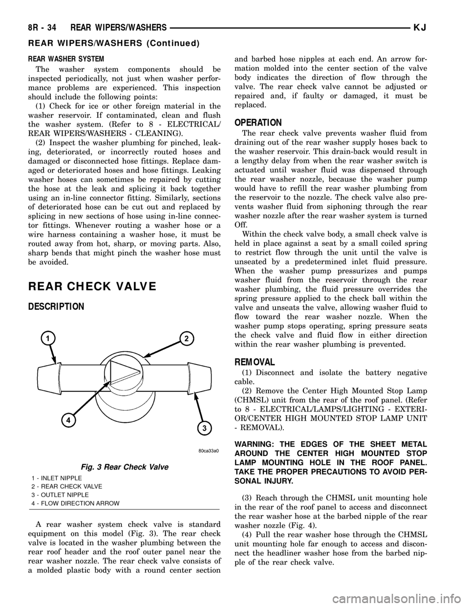
A rear washer system check valve is standard
equipment on this model (Fig. 3). The rear check
valve is located in the washer plumbing between the
rear roof header and the roof outer panel near the
rear washer nozzle. The rear check valve consists of
a molded plastic body with a round center sectionand barbed hose nipples at each end. An arrow for-
mation molded into the center section of the valve
body indicates the direction of flow through the
valve. The rear check valve cannot be adjusted or
repaired and, if faulty or damaged, it must be
replaced.
OPERATION
The rear check valve prevents washer fluid from
draining out of the rear washer supply hoses back to
the washer reservoir. This drain-back would result in
a lengthy delay from when the rear washer switch is
actuated until washer fluid was dispensed through
the rear washer nozzle, because the washer pump
would have to refill the rear washer plumbing from
the reservoir to the nozzle. The check valve also pre-
vents washer fluid from siphoning through the rear
washer nozzle after the rear washer system is turned
Off.
Within the check valve body, a small check valve is
held in place against a seat by a small coiled spring
to restrict flow through the unit until the valve is
unseated by a predetermined inlet fluid pressure.
When the washer pump pressurizes and pumps
washer fluid from the reservoir through the rear
washer plumbing, the fluid pressure overrides the
spring pressure applied to the check ball within the
valve and unseats the valve, allowing washer fluid to
flow toward the rear washer nozzle. When the
washer pump stops operating, spring pressure seats
the check valve and fluid flow in either direction
within the rear washer plumbing is prevented.
REMOVAL
(1) Disconnect and isolate the battery negative
cable.
(2) Remove the Center High Mounted Stop Lamp
(CHMSL) unit from the rear of the roof panel. (Refer
to 8 - ELECTRICAL/LAMPS/LIGHTING - EXTERI-
OR/CENTER HIGH MOUNTED STOP LAMP UNIT
- REMOVAL).
WARNING: THE EDGES OF THE SHEET METAL
AROUND THE CENTER HIGH MOUNTED STOP
LAMP MOUNTING HOLE IN THE ROOF PANEL.
TAKE THE PROPER PRECAUTIONS TO AVOID PER-
SONAL INJURY.
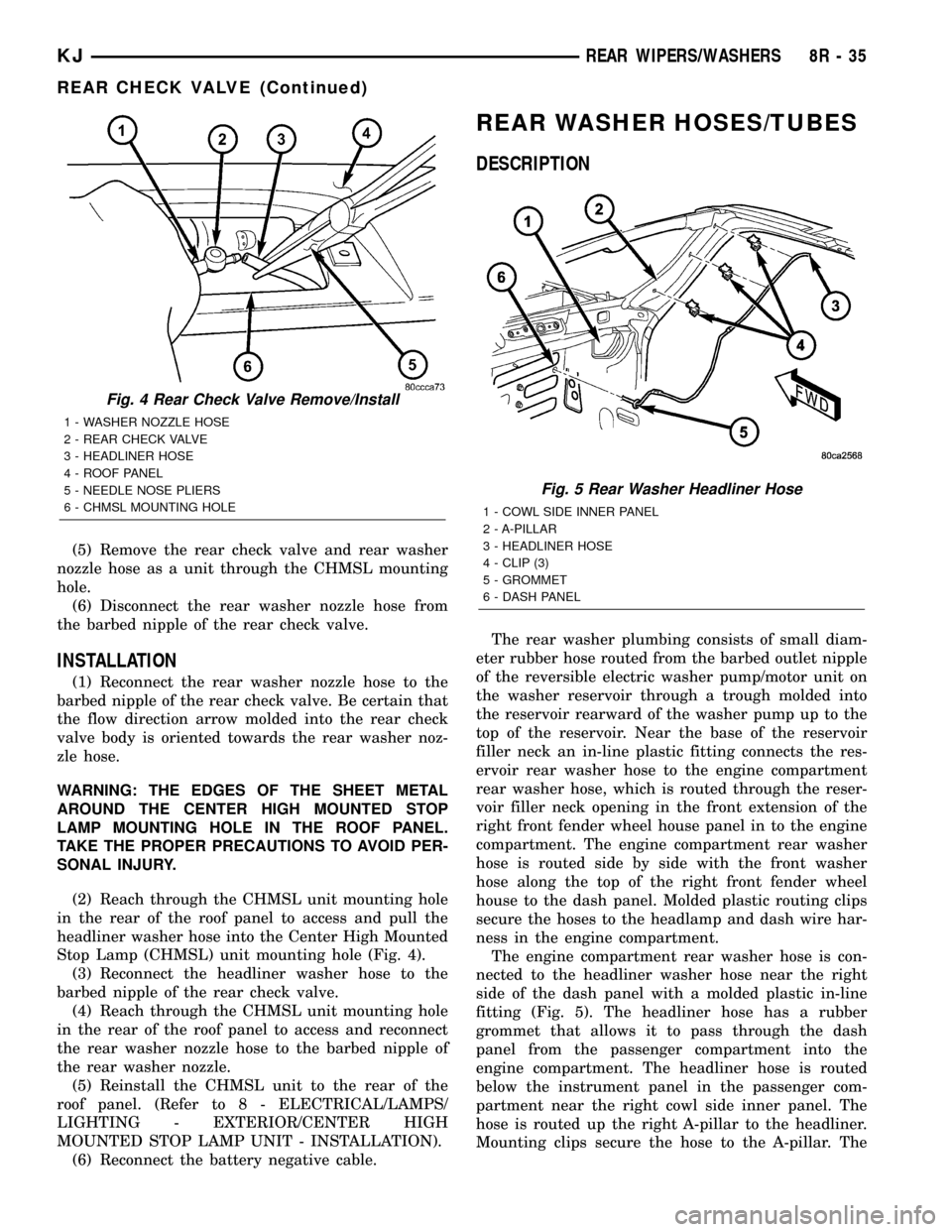
(3) Reach through the CHMSL unit mounting hole
in the rear of the roof panel to access and disconnect
the rear washer hose at the barbed nipple of the rear
washer nozzle (Fig. 4).
(4) Pull the rear washer hose through the CHMSL
unit mounting hole far enough to access and discon-
nect the headliner washer hose from the barbed nip-
ple of the rear check valve.
Fig. 3 Rear Check Valve
1 - INLET NIPPLE
2 - REAR CHECK VALVE
3 - OUTLET NIPPLE
4 - FLOW DIRECTION ARROW
8R - 34 REAR WIPERS/WASHERSKJ
REAR WIPERS/WASHERS (Continued)
Page 736 of 1803
(5) Remove the rear check valve and rear washer
nozzle hose as a unit through the CHMSL mounting
hole.
(6) Disconnect the rear washer nozzle hose from
the barbed nipple of the rear check valve.
INSTALLATION
(1) Reconnect the rear washer nozzle hose to the
barbed nipple of the rear check valve. Be certain that
the flow direction arrow molded into the rear check
valve body is oriented towards the rear washer noz-
zle hose.
WARNING: THE EDGES OF THE SHEET METAL
AROUND THE CENTER HIGH MOUNTED STOP
LAMP MOUNTING HOLE IN THE ROOF PANEL.
TAKE THE PROPER PRECAUTIONS TO AVOID PER-
SONAL INJURY.
(2) Reach through the CHMSL unit mounting hole
in the rear of the roof panel to access and pull the
headliner washer hose into the Center High Mounted
Stop Lamp (CHMSL) unit mounting hole (Fig. 4).
(3) Reconnect the headliner washer hose to the
barbed nipple of the rear check valve.
(4) Reach through the CHMSL unit mounting hole
in the rear of the roof panel to access and reconnect
the rear washer nozzle hose to the barbed nipple of
the rear washer nozzle.
(5) Reinstall the CHMSL unit to the rear of the
roof panel. (Refer to 8 - ELECTRICAL/LAMPS/
LIGHTING - EXTERIOR/CENTER HIGH
MOUNTED STOP LAMP UNIT - INSTALLATION).
(6) Reconnect the battery negative cable.
REAR WASHER HOSES/TUBES
DESCRIPTION
The rear washer plumbing consists of small diam-
eter rubber hose routed from the barbed outlet nipple
of the reversible electric washer pump/motor unit on
the washer reservoir through a trough molded into
the reservoir rearward of the washer pump up to the
top of the reservoir. Near the base of the reservoir
filler neck an in-line plastic fitting connects the res-
ervoir rear washer hose to the engine compartment
rear washer hose, which is routed through the reser-
voir filler neck opening in the front extension of the
right front fender wheel house panel in to the engine
compartment. The engine compartment rear washer
hose is routed side by side with the front washer
hose along the top of the right front fender wheel
house to the dash panel. Molded plastic routing clips
secure the hoses to the headlamp and dash wire har-
ness in the engine compartment.
The engine compartment rear washer hose is con-
nected to the headliner washer hose near the right
side of the dash panel with a molded plastic in-line
fitting (Fig. 5). The headliner hose has a rubber
grommet that allows it to pass through the dash
panel from the passenger compartment into the
engine compartment. The headliner hose is routed
below the instrument panel in the passenger com-
partment near the right cowl side inner panel. The
hose is routed up the right A-pillar to the headliner.
Mounting clips secure the hose to the A-pillar. The
Fig. 4 Rear Check Valve Remove/Install
1 - WASHER NOZZLE HOSE
2 - REAR CHECK VALVE
3 - HEADLINER HOSE
4 - ROOF PANEL
5 - NEEDLE NOSE PLIERS
6 - CHMSL MOUNTING HOLE
Fig. 5 Rear Washer Headliner Hose
1 - COWL SIDE INNER PANEL
2 - A-PILLAR
3 - HEADLINER HOSE
4 - CLIP (3)
5 - GROMMET
6 - DASH PANEL
KJREAR WIPERS/WASHERS 8R - 35
REAR CHECK VALVE (Continued)