cluster JEEP LIBERTY 2002 KJ / 1.G Workshop Manual
[x] Cancel search | Manufacturer: JEEP, Model Year: 2002, Model line: LIBERTY, Model: JEEP LIBERTY 2002 KJ / 1.GPages: 1803, PDF Size: 62.3 MB
Page 1119 of 1803
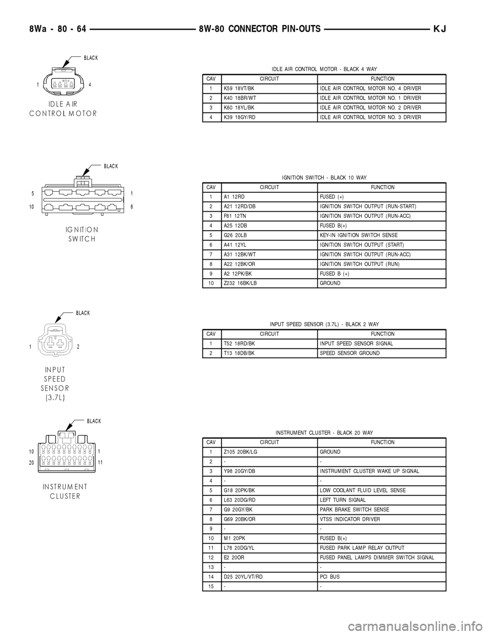
IDLE AIR CONTROL MOTOR - BLACK 4 WAY
CAV CIRCUIT FUNCTION
1 K59 18VT/BK IDLE AIR CONTROL MOTOR NO. 4 DRIVER
2 K40 18BR/WT IDLE AIR CONTROL MOTOR NO. 1 DRIVER
3 K60 18YL/BK IDLE AIR CONTROL MOTOR NO. 2 DRIVER
4 K39 18GY/RD IDLE AIR CONTROL MOTOR NO. 3 DRIVER
IGNITION SWITCH - BLACK 10 WAY
CAV CIRCUIT FUNCTION
1 A1 12RD FUSED (+)
2 A21 12RD/DB IGNITION SWITCH OUTPUT (RUN-START)
3 F81 12TN IGNITION SWITCH OUTPUT (RUN-ACC)
4 A25 12DB FUSED B(+)
5 G26 20LB KEY-IN IGNITION SWITCH SENSE
6 A41 12YL IGNITION SWITCH OUTPUT (START)
7 A31 12BK/WT IGNITION SWITCH OUTPUT (RUN-ACC)
8 A22 12BK/OR IGNITION SWITCH OUTPUT (RUN)
9 A2 12PK/BK FUSED B (+)
10 Z232 16BK/LB GROUND
INPUT SPEED SENSOR (3.7L) - BLACK 2 WAY
CAV CIRCUIT FUNCTION
1 T52 18RD/BK INPUT SPEED SENSOR SIGNAL
2 T13 18DB/BK SPEED SENSOR GROUND
INSTRUMENT CLUSTER - BLACK 20 WAY
CAV CIRCUIT FUNCTION
1 Z105 20BK/LG GROUND
2- -
3 Y98 20GY/DB INSTRUMENT CLUSTER WAKE UP SIGNAL
4- -
5 G18 20PK/BK LOW COOLANT FLUID LEVEL SENSE
6 L63 20DG/RD LEFT TURN SIGNAL
7 G9 20GY/BK PARK BRAKE SWITCH SENSE
8 G69 20BK/OR VTSS INDICATOR DRIVER
9- -
10 M1 20PK FUSED B(+)
11 L78 20DG/YL FUSED PARK LAMP RELAY OUTPUT
12 E2 20OR FUSED PANEL LAMPS DIMMER SWITCH SIGNAL
13 - -
14 D25 20YL/VT/RD PCI BUS
15 - -
8Wa - 80 - 64 8W-80 CONNECTOR PIN-OUTSKJ
Page 1120 of 1803
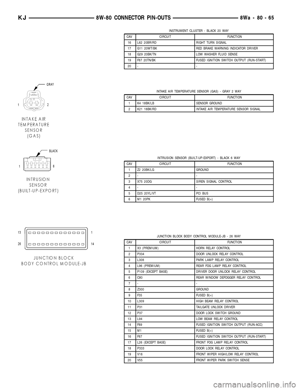
INSTRUMENT CLUSTER - BLACK 20 WAY
CAV CIRCUIT FUNCTION
16 L62 20BR/RD RIGHT TURN SIGNAL
17 G11 20WT/BK RED BRAKE WARNING INDICATOR DRIVER
18 G29 20BK/TN LOW WASHER FLUID SENSE
19 F87 20TN/BK FUSED IGNITION SWITCH OUTPUT (RUN-START)
20 - -
INTAKE AIR TEMPERATURE SENSOR (GAS) - GRAY 2 WAY
CAV CIRCUIT FUNCTION
1 K4 18BK/LB SENSOR GROUND
2 K21 18BK/RD INTAKE AIR TEMPERATURE SENSOR SIGNAL
INTRUSION SENSOR (BUILT-UP-EXPORT) - BLACK 6 WAY
CAV CIRCUIT FUNCTION
1 Z2 20BK/LG GROUND
2- -
3 X75 20DG SIREN SIGNAL CONTROL
4- -
5 D25 20YL/VT PCI BUS
6 M1 20PK FUSED B(+)
JUNCTION BLOCK BODY CONTROL MODULE-JB - 26 WAY
CAV CIRCUIT FUNCTION
1 X3 (PREMIUM) HORN RELAY CONTROL
2 P334 DOOR UNLOCK RELAY CONTROL
3 L308 PARK LAMP RELAY CONTROL
4 L96 (PREMIUM) REAR FOG LAMP RELAY CONTROL
5 P109 (EXCEPT BASE) DRIVER DOOR UNLOCK RELAY CONTROL
6 C80 REAR WINDOW DEFOGGER RELAY CONTROL
7- -
8 Z300 GROUND
9 F35 FUSED B(+)
10 L309 HIGH BEAM RELAY CONTROL
11 P31 TAILGATE UNLOCK DRIVER
12 P37 DOOR LOCK SWITCH GROUND
13 L94 LOW BEAM RELAY CONTROL
14 F89 FUSED IGNITION SWITCH OUTPUT (RUN-ACC)
15 M1 FUSED B(+)
16 F87 FUSED IGNITION SWITCH OUTPUT (RUN-START)
17 L26 (EXCEPT BASE) FRONT FOG LAMP RELAY CONTROL
18 P333 DOOR LOCK RELAY CONTROL
19 V16 FRONT WIPER HIGH/LOW RELAY CONTROL
20 V55 FRONT WIPER PARK SWITCH SENSE
KJ8W-80 CONNECTOR PIN-OUTS8Wa-80-65
Page 1160 of 1803
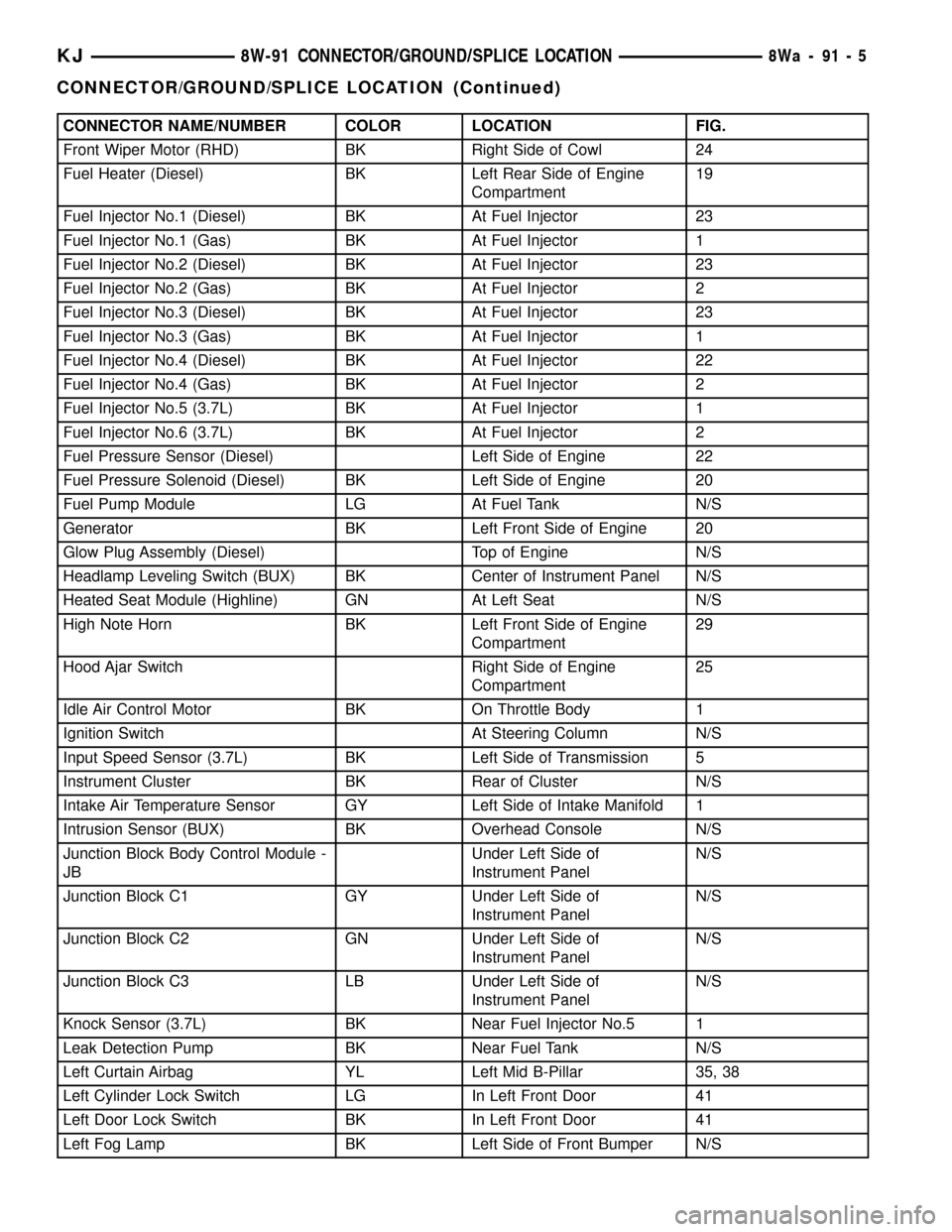
CONNECTOR NAME/NUMBER COLOR LOCATION FIG.
Front Wiper Motor (RHD) BK Right Side of Cowl 24
Fuel Heater (Diesel) BK Left Rear Side of Engine
Compartment19
Fuel Injector No.1 (Diesel) BK At Fuel Injector 23
Fuel Injector No.1 (Gas) BK At Fuel Injector 1
Fuel Injector No.2 (Diesel) BK At Fuel Injector 23
Fuel Injector No.2 (Gas) BK At Fuel Injector 2
Fuel Injector No.3 (Diesel) BK At Fuel Injector 23
Fuel Injector No.3 (Gas) BK At Fuel Injector 1
Fuel Injector No.4 (Diesel) BK At Fuel Injector 22
Fuel Injector No.4 (Gas) BK At Fuel Injector 2
Fuel Injector No.5 (3.7L) BK At Fuel Injector 1
Fuel Injector No.6 (3.7L) BK At Fuel Injector 2
Fuel Pressure Sensor (Diesel) Left Side of Engine 22
Fuel Pressure Solenoid (Diesel) BK Left Side of Engine 20
Fuel Pump Module LG At Fuel Tank N/S
Generator BK Left Front Side of Engine 20
Glow Plug Assembly (Diesel) Top of Engine N/S
Headlamp Leveling Switch (BUX) BK Center of Instrument Panel N/S
Heated Seat Module (Highline) GN At Left Seat N/S
High Note Horn BK Left Front Side of Engine
Compartment29
Hood Ajar Switch Right Side of Engine
Compartment25
Idle Air Control Motor BK On Throttle Body 1
Ignition Switch At Steering Column N/S
Input Speed Sensor (3.7L) BK Left Side of Transmission 5
Instrument Cluster BK Rear of Cluster N/S
Intake Air Temperature Sensor GY Left Side of Intake Manifold 1
Intrusion Sensor (BUX) BK Overhead Console N/S
Junction Block Body Control Module -
JBUnder Left Side of
Instrument PanelN/S
Junction Block C1 GY Under Left Side of
Instrument PanelN/S
Junction Block C2 GN Under Left Side of
Instrument PanelN/S
Junction Block C3 LB Under Left Side of
Instrument PanelN/S
Knock Sensor (3.7L) BK Near Fuel Injector No.5 1
Leak Detection Pump BK Near Fuel Tank N/S
Left Curtain Airbag YL Left Mid B-Pillar 35, 38
Left Cylinder Lock Switch LG In Left Front Door 41
Left Door Lock Switch BK In Left Front Door 41
Left Fog Lamp BK Left Side of Front Bumper N/S
KJ8W-91 CONNECTOR/GROUND/SPLICE LOCATION8Wa-91-5
CONNECTOR/GROUND/SPLICE LOCATION (Continued)
Page 1167 of 1803
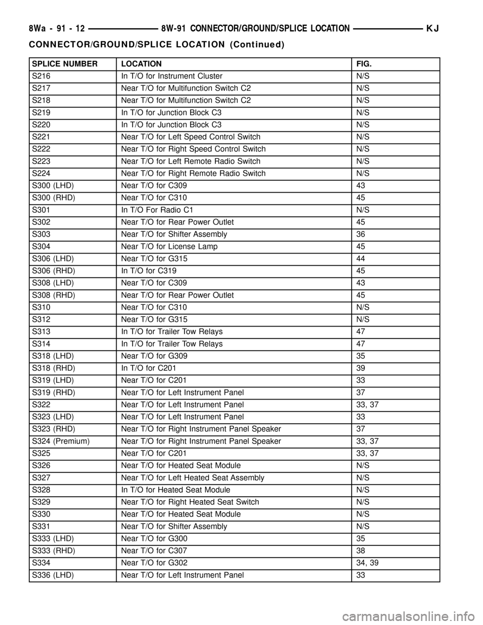
SPLICE NUMBER LOCATION FIG.
S216 In T/O for Instrument Cluster N/S
S217 Near T/O for Multifunction Switch C2 N/S
S218 Near T/O for Multifunction Switch C2 N/S
S219 In T/O for Junction Block C3 N/S
S220 In T/O for Junction Block C3 N/S
S221 Near T/O for Left Speed Control Switch N/S
S222 Near T/O for Right Speed Control Switch N/S
S223 Near T/O for Left Remote Radio Switch N/S
S224 Near T/O for Right Remote Radio Switch N/S
S300 (LHD) Near T/O for C309 43
S300 (RHD) Near T/O for C310 45
S301 In T/O For Radio C1 N/S
S302 Near T/O for Rear Power Outlet 45
S303 Near T/O for Shifter Assembly 36
S304 Near T/O for License Lamp 45
S306 (LHD) Near T/O for G315 44
S306 (RHD) In T/O for C319 45
S308 (LHD) Near T/O for C309 43
S308 (RHD) Near T/O for Rear Power Outlet 45
S310 Near T/O for C310 N/S
S312 Near T/O for G315 N/S
S313 In T/O for Trailer Tow Relays 47
S314 In T/O for Trailer Tow Relays 47
S318 (LHD) Near T/O for G309 35
S318 (RHD) In T/O for C201 39
S319 (LHD) Near T/O for C201 33
S319 (RHD) Near T/O for Left Instrument Panel 37
S322 Near T/O for Left Instrument Panel 33, 37
S323 (LHD) Near T/O for Left Instrument Panel 33
S323 (RHD) Near T/O for Right Instrument Panel Speaker 37
S324 (Premium) Near T/O for Right Instrument Panel Speaker 33, 37
S325 Near T/O for C201 33, 37
S326 Near T/O for Heated Seat Module N/S
S327 Near T/O for Left Heated Seat Assembly N/S
S328 In T/O for Heated Seat Module N/S
S329 Near T/O for Right Heated Seat Switch N/S
S330 Near T/O for Heated Seat Module N/S
S331 Near T/O for Shifter Assembly N/S
S333 (LHD) Near T/O for G300 35
S333 (RHD) Near T/O for C307 38
S334 Near T/O for G302 34, 39
S336 (LHD) Near T/O for Left Instrument Panel 33
8Wa - 91 - 12 8W-91 CONNECTOR/GROUND/SPLICE LOCATIONKJ
CONNECTOR/GROUND/SPLICE LOCATION (Continued)
Page 1391 of 1803

FUEL LEVEL SENDING UNIT /
SENSOR
DESCRIPTION
The fuel gauge sending unit (fuel level sensor) is
attached to the side of the fuel pump module. The
sending unit consists of a float, an arm, and a vari-
able resistor track (card).
OPERATION
The fuel pump module has 4 different circuits
(wires). Two of these circuits are used for the fuel
gauge sending unit for fuel gauge operation, and for
certain OBD II emission requirements. The other 2
wires are used for electric fuel pump operation.
For Fuel Gauge Operation:A constant current
source of approximately 32 milliamps is supplied to
the resistor track on the fuel gauge sending unit.
This is fed directly from the Powertrain Control Mod-
ule (PCM).NOTE: For diagnostic purposes, this
12V power source can only be verified with the
circuit opened (fuel pump module electrical
connector unplugged). With the connectors
plugged, output voltages will vary from about
0.6 volts at FULL, to about 8.6 volts at EMPTY
(about 8.6 volts at EMPTY for Jeep models, and
about 7.0 volts at EMPTY for Dodge Truck mod-
els).The resistor track is used to vary the voltage
(resistance) depending on fuel tank float level. As
fuel level increases, the float and arm move up,
which decreases voltage. As fuel level decreases, the
float and arm move down, which increases voltage.
The varied voltage signal is returned back to the
PCM through the sensor return circuit.
Both of the electrical circuits between the fuel
gauge sending unit and the PCM are hard-wired (not
multi-plexed). After the voltage signal is sent from
the resistor track, and back to the PCM, the PCM
will interpret the resistance (voltage) data and send
a message across the multi-plex bus circuits to the
instrument panel cluster. Here it is translated into
the appropriate fuel gauge level reading. Refer to
Instrument Panel for additional information.
For OBD II Emission Monitor Requirements:
The PCM will monitor the voltage output sent from
the resistor track on the sending unit to indicate fuel
level. The purpose of this feature is to prevent the
OBD II system from recording/setting false misfire
and fuel system monitor diagnostic trouble codes.
The feature is activated if the fuel level in the tank
is less than approximately 15 percent of its rated
capacity. If equipped with a Leak Detection Pump
(EVAP system monitor), this feature will also be acti-
vated if the fuel level in the tank is more than
approximately 85 percent of its rated capacity.
DIAGNOSIS AND TESTING - FUEL LEVEL
SENDING UNIT
The fuel level sending unit contains a variable
resistor (track). As the float moves up or down, elec-
trical resistance will change. Refer to Instrument
Panel and Gauges for Fuel Gauge testing. To test the
gauge sending unit only, it must be removed from
vehicle. The unit is a separate part of the lower fuel
pump module section. Refer to Fuel Pump Module
Removal/Installation for procedures (remove only the
upper section of the fuel pump module). Measure the
resistance across the sending unit terminals. With
float in up position, resistance should be 20 ohms (+/-
5%). With float in down position, resistance should be
270 ohms (+/- 5%).
REMOVAL
The fuel level sending unit (fuel level sensor) and
float assembly is located on the side of the lower sec-
tion of the fuel pump module. The lower section of
the fuel pump module is located within the fuel tank.
(1) Remove lower section of fuel pump module
from fuel tank. Refer to Fuel Pump Module Removal/
Installation.
(2) To remove sending unit from pump module, lift
on plastic locking tab (Fig. 8) while sliding sending
unit upwards.
(3) Disconnect 4±wire electrical connector (Fig. 9)
from bottom of upper section of fuel pump module.
Separate necessary sending unit wiring.
Fig. 8 FUEL LEVEL SENDING UNIT
1 - LIFT TAB HERE FOR REMOVAL
2 - FUEL LEVEL SENDING UNIT
3 - LOWER SECTION OF PUMP MODULE
KJFUEL DELIVERY 14 - 9
Page 1440 of 1803

KEY-IN IGNITION SWITCH
DESCRIPTION
The key-in ignition switch is integral to the igni-
tion switch, which is mounted on the left side of the
steering column, opposite the ignition lock cylinder.
It closes a path to ground for the instrument cluster
chime warning circuitry when the ignition key is
inserted in the ignition lock cylinder and the driver
door jamb switch is closed (driver door is open). The
key-in ignition switch opens the ground path when
the key is removed from the ignition lock cylinder.
The key-in ignition switch cannot be repaired and,
if faulty or damaged, the entire ignition switch must
be replaced. (Refer to 19 - STEERING/COLUMN/IG-
NITION SWITCH - REMOVAL).
DIAGNOSIS AND TESTING - KEY-IN IGNITION
SWITCH
For circuit descriptions and diagrams, Refer to the
appropriate sections on the individual components.
WARNING: ON VEHICLES EQUIPPED WITH AIR-
BAGS, REFER TO ELECTRICAL - PASSIVE
RESTRAINT SYSTEMS BEFORE ATTEMPTING ANY
STEERING WHEEL, STEERING COLUMN, OR
INSTRUMENT PANEL COMPONENT DIAGNOSIS OR
SERVICE. FAILURE TO TAKE THE PROPER PRE-
CAUTIONS COULD RESULT IN ACCIDENTAL AIR-
BAG DEPLOYMENT AND POSSIBLE PERSONAL
INJURY.
(1) Disconnect and isolate the battery negative
cable. Remove the steering column shrouds. Unplug
the key-in ignition switch wire harness connector
from the ignition switch.
(2) Check for continuity between the key-in switch
sense circuit and the left front door jamb switch
sense circuit terminals of the key-in ignition switch.
There should be continuity with the key in the igni-
tion lock cylinder, and no continuity with the key
removed from the ignition lock cylinder. If OK, go to
Step 3. If not OK, replace the faulty ignition switch
assembly.
(3) Check for continuity between the left front door
jamb switch sense circuit cavity of the key-in ignition
switch wire harness connector and a good ground.
There should be continuity with the driver door open,
and no continuity with the driver door closed. If OK,
see the diagnosis for Instrument Cluster in this
group. If not OK, repair the circuit to the driver door
jamb switch as required.
LOCK CYLINDER
REMOVAL
The ignition key must be in the key cylinder for
cylinder removal. The key cylinder must be removed
first before removing ignition switch.
(1) If equipped with an automatic transmission,
place shifter in PARK position.
(2) Remove the lower shroud cover.
(3) Remove the remote keyless entry (R.K.E.) mod-
ule.
(4) Remove the halo ring around the lock cylinder.
(5) Rotate key to ON position.
(6) A release tang is located on bottom of key cyl-
inder (Fig. 10).
(7) Position a small screwdriver or pin punch into
tang access hole on bottom of steering column (Fig.
11).
(8) Push the pin punch up while pulling key cylin-
der from steering column.
Fig. 10 LOCK CYLINDER RELEASE TANG
1 - Lock Cylinder
2 - Release Tang
19 - 10 COLUMNKJ
Page 1612 of 1803

INSTRUMENT PANEL
TABLE OF CONTENTS
page page
CLUSTER BEZEL
REMOVAL............................147
INSTALLATION........................147
GLOVE BOX
REMOVAL............................148
INSTALLATION........................148
GLOVE BOX LATCH
REMOVAL............................148
INSTALLATION........................148
GLOVE BOX LATCH STRIKER
REMOVAL............................148
INSTALLATION........................149
INSTRUMENT PANEL ASSEMBLY
REMOVAL............................149
INSTALLATION........................151
INSTRUMENT PANEL TOP COVER
REMOVAL............................152INSTALLATION........................153
INSTRUMENT PANEL END CAP
REMOVAL............................153
INSTALLATION........................153
INSTRUMENT PANEL DRIVER SIDE BEZELS
REMOVAL............................153
INSTALLATION........................154
INSTRUMENT PANEL CENTER BEZEL
REMOVAL............................154
INSTALLATION........................154
INSTRUMENT PANEL PASSENGER SIDE
BEZEL
REMOVAL............................154
INSTALLATION........................154
KNEE BLOCKER
REMOVAL............................155
INSTALLATION........................155
CLUSTER BEZEL
REMOVAL
WARNING: ON VEHICLES EQUIPPED WITH AIR-
BAGS, DISABLE THE AIRBAG SYSTEM BEFORE
ATTEMPTING ANY STEERING WHEEL, STEERING
COLUMN, SEAT BELT TENSIONER, OR INSTRU-
MENT PANEL COMPONENT DIAGNOSIS OR SER-
VICE. DISCONNECT AND ISOLATE THE BATTERY
NEGATIVE (GROUND) CABLE, THEN WAIT TWO
MINUTES FOR THE AIRBAG SYSTEM CAPACITOR
TO DISCHARGE BEFORE PERFORMING FURTHER
DIAGNOSIS OR SERVICE. THIS IS THE ONLY SURE
WAY TO DISABLE THE AIRBAG SYSTEM. FAILURE
TO TAKE THE PROPER PRECAUTIONS COULD
RESULT IN ACCIDENTAL AIRBAG DEPLOYMENT
AND POSSIBLE PERSONAL INJURY.
(1) Remove the drives side trim bezels. (Refer to
23 - BODY/INSTRUMENT PANEL/INSTRUMENT
PANEL DRIVER SIDE BEZEL - REMOVAL)
(2) Remove the instrument panel top cover. (Refer
to 23 - BODY/INSTRUMENT PANEL/INSTRUMENT
PANEL TOP COVER - REMOVAL)
(3) Remove the seven screws and remove the clus-
ter bezel.
INSTALLATION
WARNING: ON VEHICLES EQUIPPED WITH AIR-
BAGS, DISABLE THE AIRBAG SYSTEM BEFORE
ATTEMPTING ANY STEERING WHEEL, STEERING
COLUMN, SEAT BELT TENSIONER, OR INSTRU-
MENT PANEL COMPONENT DIAGNOSIS OR SER-
VICE. DISCONNECT AND ISOLATE THE BATTERY
NEGATIVE (GROUND) CABLE, THEN WAIT TWO
MINUTES FOR THE AIRBAG SYSTEM CAPACITOR
TO DISCHARGE BEFORE PERFORMING FURTHER
DIAGNOSIS OR SERVICE. THIS IS THE ONLY SURE
WAY TO DISABLE THE AIRBAG SYSTEM. FAILURE
TO TAKE THE PROPER PRECAUTIONS COULD
RESULT IN ACCIDENTAL AIRBAG DEPLOYMENT
AND POSSIBLE PERSONAL INJURY.
(1) Install the cluster bezel and the seven screws.
(2) Install the instrument panel top cover. (Refer
to 23 - BODY/INSTRUMENT PANEL/INSTRUMENT
PANEL TOP COVER - INSTALLATION)
(3) Install the drives side trim bezels. (Refer to 23
- BODY/INSTRUMENT PANEL/INSTRUMENT
PANEL DRIVER SIDE BEZEL - INSTALLATION)
KJINSTRUMENT PANEL 23 - 147
Page 1668 of 1803

(2) Resistance between terminals 85 and 86 (elec-
tromagnet) should be 67.5 to 82.5 ohms. If OK, go to
Step 3. If not OK, replace the faulty relay.
(3) Connect a battery to terminals 85 and 86.
There should now be continuity between terminals
30 and 87, and no continuity between terminals 87A
and 30. If OK, see Relay Circuit Test. If not OK,
replace the faulty relay.
RELAY CIRCUIT TEST
For circuit descriptions and diagrams, (Refer to
Appropriate Wiring Information).
(1) The relay common feed terminal cavity (30) is
connected to fused battery feed. There should be bat-
tery voltage at the cavity for relay terminal 30 at all
times. If OK, go to Step 2. If not OK, repair the open
circuit to the fuse in the PDC as required.
(2) The relay normally closed terminal (87A) is not
used in this application. Go to Step 3.
(3) The relay normally open terminal cavity (87) is
connected to the compressor clutch coil. There should
be continuity between this cavity and the A/C com-
pressor clutch relay output circuit cavity of the com-
pressor clutch coil wire harness connector. If OK, go
to Step 4. If not OK, repair the open circuit as
required.
(4) The relay coil battery terminal (86) is con-
nected to the fused ignition switch output (run/start)circuit. There should be battery voltage at the cavity
for relay terminal 86 with the ignition switch in the
On position. If OK, go to Step 5. If not OK, repair the
open circuit to the fuse in the junction block as
required.
(5) The coil ground terminal cavity (85) is switched
to ground through the Powertrain Control Module
(PCM). There should be continuity between this cav-
ity and the A/C compressor clutch relay control cir-
cuit cavity of the PCM wire harness connector C
(gray) at all times. If not OK, repair the open circuit
as required.
REMOVAL
(1) Disconnect and isolate the battery negative
cable.
(2) Remove the cover from the Power Distribution
Center (PDC).
(3) Refer to the label on the PDC for compressor
clutch relay identification and location.
(4) Unplug the compressor clutch relay from the
PDC.
INSTALLATION
(1) Install the compressor clutch relay by aligning
the relay terminals with the cavities in the PDC and
pushing the relay firmly into place.
(2) Install the PDC cover.
(3) Connect the battery negative cable.
(4) Test the relay operation.
A/C HEATER CONTROL
DESCRIPTION
Both the heater-only and A/C heater systems use a
combination of mechanical, electrical, and vacuum
controls. These controls provide the vehicle operator
with a number of setting options to help control the
climate and comfort within the vehicle. Refer to the
owner's manual in the vehicle glove box for more
information on the features, use, and suggested oper-
ation of these controls.
The heater-only or A/C heater control panel is
located to the right of the instrument cluster on the
instrument panel. The control panel contains a rota-
ry-type temperature control knob, a rotary-type mode
control switch knob, and a rotary-type blower motor
speed switch knob. The control also has a push but-
ton to activate the rear window defogger.
The heater-only or A/C heater control panel cannot
be repaired. If faulty or damaged, the entire unit
must be replaced. The illumination lamps are avail-
able for service replacement.
Fig. 10 COMPRESSOR CLUTCH RELAY
30 - COMMON FEED
85 - COIL GROUND
86 - COIL BATTERY
87 - NORMALLY OPEN
87A - NORMALLY CLOSED
24 - 16 CONTROLSKJ
A/C COMPRESSOR CLUTCH RELAY (Continued)
Page 1720 of 1803
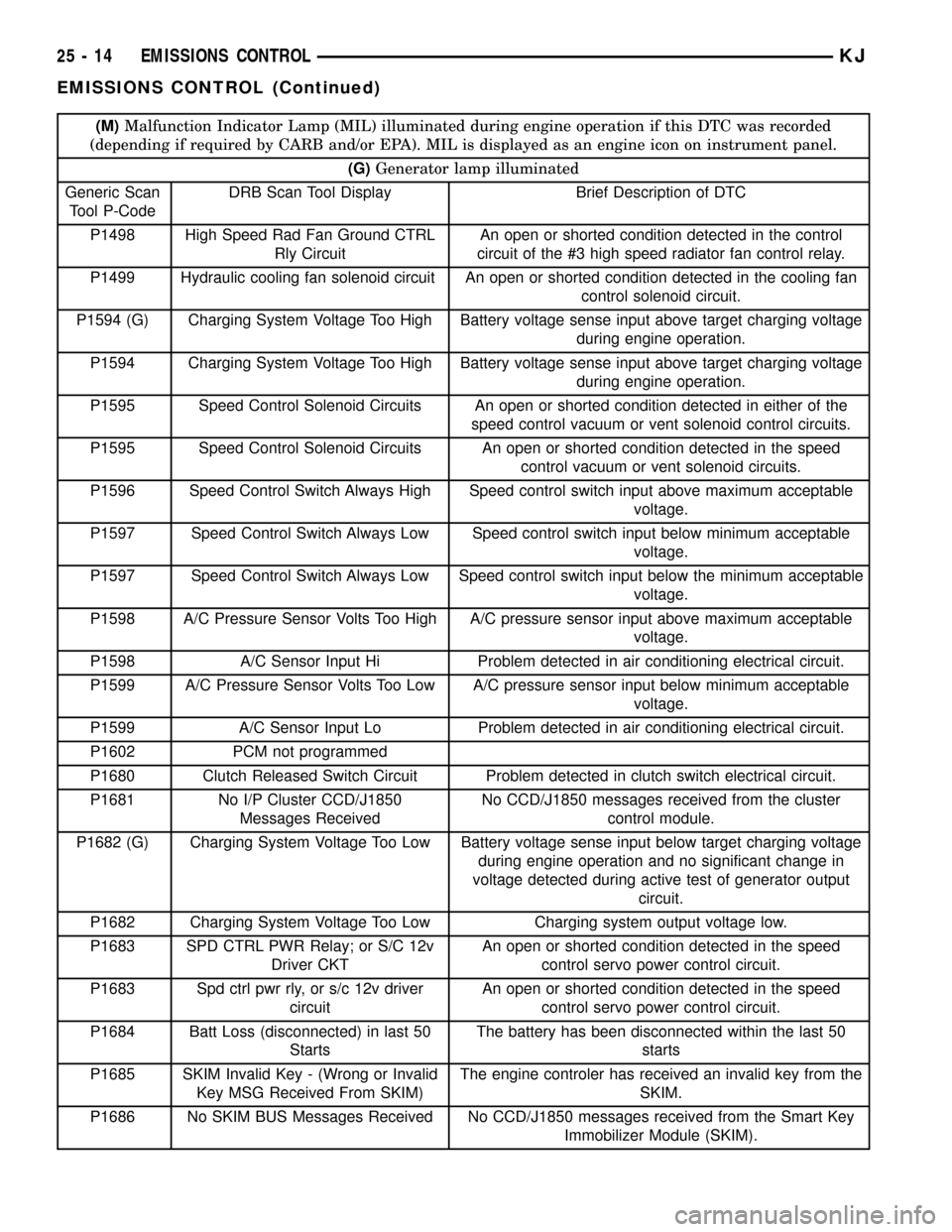
(M)Malfunction Indicator Lamp (MIL) illuminated during engine operation if this DTC was recorded
(depending if required by CARB and/or EPA). MIL is displayed as an engine icon on instrument panel.
(G)Generator lamp illuminated
Generic Scan
Tool P-CodeDRB Scan Tool Display Brief Description of DTC
P1498 High Speed Rad Fan Ground CTRL
Rly CircuitAn open or shorted condition detected in the control
circuit of the #3 high speed radiator fan control relay.
P1499 Hydraulic cooling fan solenoid circuit An open or shorted condition detected in the cooling fan
control solenoid circuit.
P1594 (G) Charging System Voltage Too High Battery voltage sense input above target charging voltage
during engine operation.
P1594 Charging System Voltage Too High Battery voltage sense input above target charging voltage
during engine operation.
P1595 Speed Control Solenoid Circuits An open or shorted condition detected in either of the
speed control vacuum or vent solenoid control circuits.
P1595 Speed Control Solenoid Circuits An open or shorted condition detected in the speed
control vacuum or vent solenoid circuits.
P1596 Speed Control Switch Always High Speed control switch input above maximum acceptable
voltage.
P1597 Speed Control Switch Always Low Speed control switch input below minimum acceptable
voltage.
P1597 Speed Control Switch Always Low Speed control switch input below the minimum acceptable
voltage.
P1598 A/C Pressure Sensor Volts Too High A/C pressure sensor input above maximum acceptable
voltage.
P1598 A/C Sensor Input Hi Problem detected in air conditioning electrical circuit.
P1599 A/C Pressure Sensor Volts Too Low A/C pressure sensor input below minimum acceptable
voltage.
P1599 A/C Sensor Input Lo Problem detected in air conditioning electrical circuit.
P1602 PCM not programmed
P1680 Clutch Released Switch Circuit Problem detected in clutch switch electrical circuit.
P1681 No I/P Cluster CCD/J1850
Messages ReceivedNo CCD/J1850 messages received from the cluster
control module.
P1682 (G) Charging System Voltage Too Low Battery voltage sense input below target charging voltage
during engine operation and no significant change in
voltage detected during active test of generator output
circuit.
P1682 Charging System Voltage Too Low Charging system output voltage low.
P1683 SPD CTRL PWR Relay; or S/C 12v
Driver CKTAn open or shorted condition detected in the speed
control servo power control circuit.
P1683 Spd ctrl pwr rly, or s/c 12v driver
circuitAn open or shorted condition detected in the speed
control servo power control circuit.
P1684 Batt Loss (disconnected) in last 50
StartsThe battery has been disconnected within the last 50
starts
P1685 SKIM Invalid Key - (Wrong or Invalid
Key MSG Received From SKIM)The engine controler has received an invalid key from the
SKIM.
P1686 No SKIM BUS Messages Received No CCD/J1850 messages received from the Smart Key
Immobilizer Module (SKIM).
25 - 14 EMISSIONS CONTROLKJ
EMISSIONS CONTROL (Continued)
Page 1721 of 1803
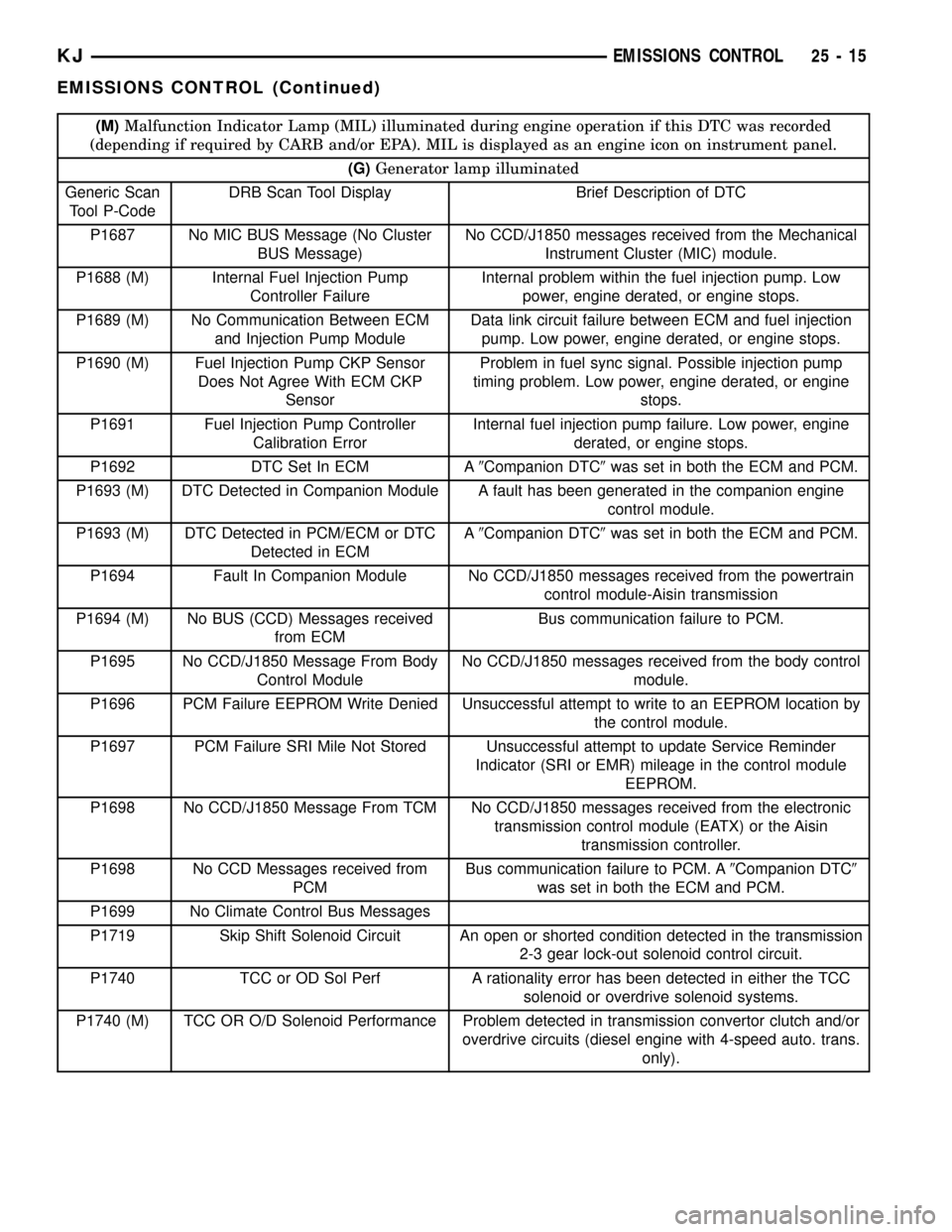
(M)Malfunction Indicator Lamp (MIL) illuminated during engine operation if this DTC was recorded
(depending if required by CARB and/or EPA). MIL is displayed as an engine icon on instrument panel.
(G)Generator lamp illuminated
Generic Scan
Tool P-CodeDRB Scan Tool Display Brief Description of DTC
P1687 No MIC BUS Message (No Cluster
BUS Message)No CCD/J1850 messages received from the Mechanical
Instrument Cluster (MIC) module.
P1688 (M) Internal Fuel Injection Pump
Controller FailureInternal problem within the fuel injection pump. Low
power, engine derated, or engine stops.
P1689 (M) No Communication Between ECM
and Injection Pump ModuleData link circuit failure between ECM and fuel injection
pump. Low power, engine derated, or engine stops.
P1690 (M) Fuel Injection Pump CKP Sensor
Does Not Agree With ECM CKP
SensorProblem in fuel sync signal. Possible injection pump
timing problem. Low power, engine derated, or engine
stops.
P1691 Fuel Injection Pump Controller
Calibration ErrorInternal fuel injection pump failure. Low power, engine
derated, or engine stops.
P1692 DTC Set In ECM A9Companion DTC9was set in both the ECM and PCM.
P1693 (M) DTC Detected in Companion Module A fault has been generated in the companion engine
control module.
P1693 (M) DTC Detected in PCM/ECM or DTC
Detected in ECMA9Companion DTC9was set in both the ECM and PCM.
P1694 Fault In Companion Module No CCD/J1850 messages received from the powertrain
control module-Aisin transmission
P1694 (M) No BUS (CCD) Messages received
from ECMBus communication failure to PCM.
P1695 No CCD/J1850 Message From Body
Control ModuleNo CCD/J1850 messages received from the body control
module.
P1696 PCM Failure EEPROM Write Denied Unsuccessful attempt to write to an EEPROM location by
the control module.
P1697 PCM Failure SRI Mile Not Stored Unsuccessful attempt to update Service Reminder
Indicator (SRI or EMR) mileage in the control module
EEPROM.
P1698 No CCD/J1850 Message From TCM No CCD/J1850 messages received from the electronic
transmission control module (EATX) or the Aisin
transmission controller.
P1698 No CCD Messages received from
PCMBus communication failure to PCM. A9Companion DTC9
was set in both the ECM and PCM.
P1699 No Climate Control Bus Messages
P1719 Skip Shift Solenoid Circuit An open or shorted condition detected in the transmission
2-3 gear lock-out solenoid control circuit.
P1740 TCC or OD Sol Perf A rationality error has been detected in either the TCC
solenoid or overdrive solenoid systems.
P1740 (M) TCC OR O/D Solenoid Performance Problem detected in transmission convertor clutch and/or
overdrive circuits (diesel engine with 4-speed auto. trans.
only).
KJEMISSIONS CONTROL 25 - 15
EMISSIONS CONTROL (Continued)