ECU JEEP LIBERTY 2002 KJ / 1.G User Guide
[x] Cancel search | Manufacturer: JEEP, Model Year: 2002, Model line: LIBERTY, Model: JEEP LIBERTY 2002 KJ / 1.GPages: 1803, PDF Size: 62.3 MB
Page 46 of 1803
LOWER BALL JOINT
REMOVAL
(1) Remove the tire and wheel assembly.
(2) Remove the brake caliper and rotor (Refer to 5
- BRAKES/HYDRAULIC/MECHANICAL/ROTORS -
REMOVAL).
(3) Disconnect the tie rod from the steering
knuckle (Refer to 19 - STEERING/LINKAGE/TIE
ROD END - REMOVAL).
(4) Remove the steering knuckle (Refer to 2 - SUS-
PENSION/FRONT/KNUCKLE - REMOVAL).
(5) Move the halfshaft to the side and support the
halfshaft out of the way (If Equipped).
NOTE: Extreme pressure lubrication must be used
on the threaded portions of the tool. This will
increase the longevity of the tool and insure proper
operation during the removal and installation pro-
cess.
(6) Secure the steering knuckle in a vise.
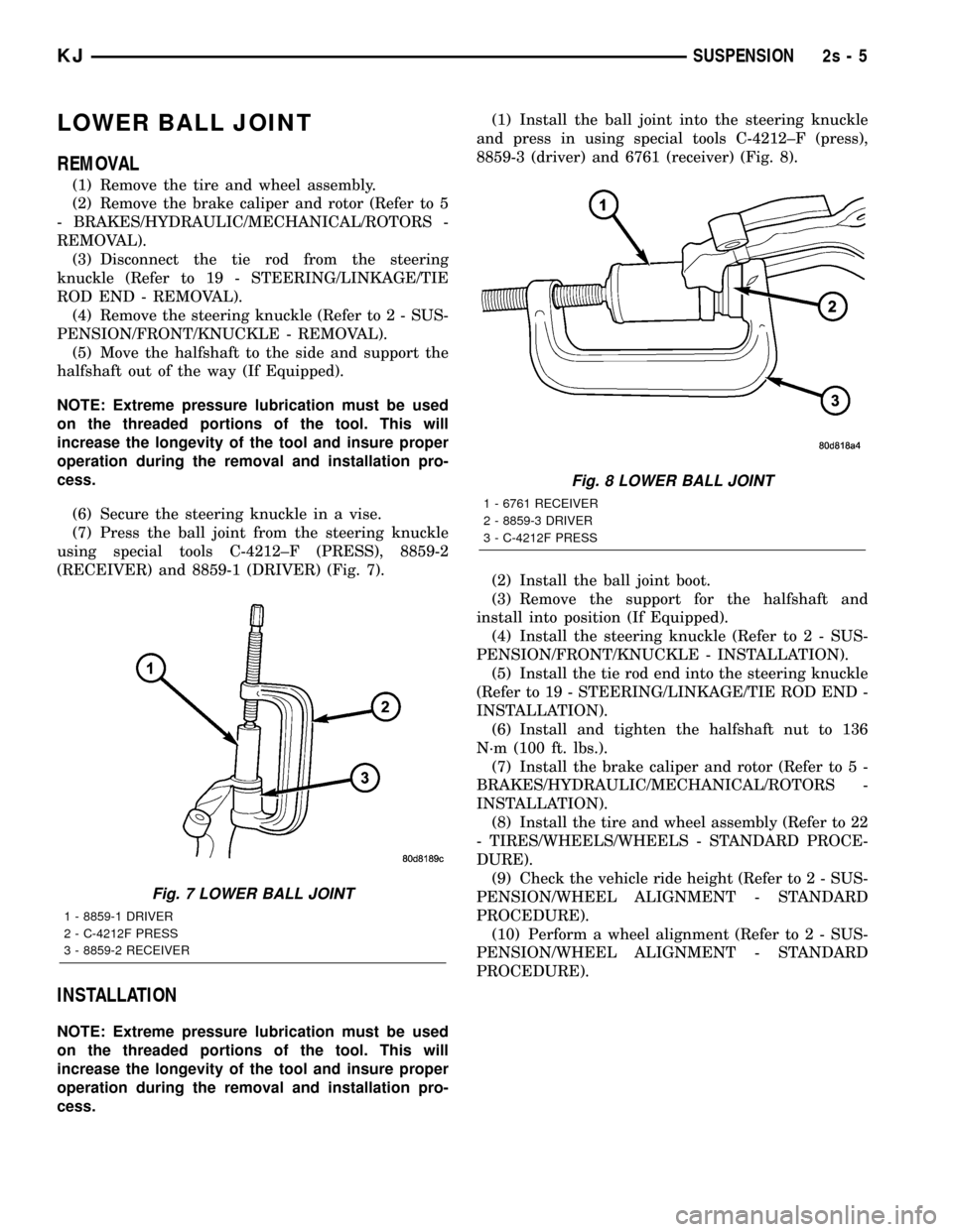
(7) Press the ball joint from the steering knuckle
using special tools C-4212±F (PRESS), 8859-2
(RECEIVER) and 8859-1 (DRIVER) (Fig. 7).
INSTALLATION
NOTE: Extreme pressure lubrication must be used
on the threaded portions of the tool. This will
increase the longevity of the tool and insure proper
operation during the removal and installation pro-
cess.(1) Install the ball joint into the steering knuckle
and press in using special tools C-4212±F (press),
8859-3 (driver) and 6761 (receiver) (Fig. 8).
(2) Install the ball joint boot.
(3) Remove the support for the halfshaft and
install into position (If Equipped).
(4) Install the steering knuckle (Refer to 2 - SUS-
PENSION/FRONT/KNUCKLE - INSTALLATION).
(5) Install the tie rod end into the steering knuckle
(Refer to 19 - STEERING/LINKAGE/TIE ROD END -
INSTALLATION).
(6) Install and tighten the halfshaft nut to 136
N´m (100 ft. lbs.).
(7) Install the brake caliper and rotor (Refer to 5 -
BRAKES/HYDRAULIC/MECHANICAL/ROTORS -
INSTALLATION).
(8) Install the tire and wheel assembly (Refer to 22
- TIRES/WHEELS/WHEELS - STANDARD PROCE-
DURE).
(9) Check the vehicle ride height (Refer to 2 - SUS-
PENSION/WHEEL ALIGNMENT - STANDARD
PROCEDURE).
(10) Perform a wheel alignment (Refer to 2 - SUS-
PENSION/WHEEL ALIGNMENT - STANDARD
PROCEDURE).
Fig. 7 LOWER BALL JOINT
1 - 8859-1 DRIVER
2 - C-4212F PRESS
3 - 8859-2 RECEIVER
Fig. 8 LOWER BALL JOINT
1 - 6761 RECEIVER
2 - 8859-3 DRIVER
3 - C-4212F PRESS
KJSUSPENSION 2s - 5
Page 47 of 1803
REAR
SPECIAL TOOLS
REAR SUSPENSION
UPPER BALL JOINT
REMOVAL
(1) Raise and support the vehicle.
(2) Support the rear axle with a hydraulic jack.
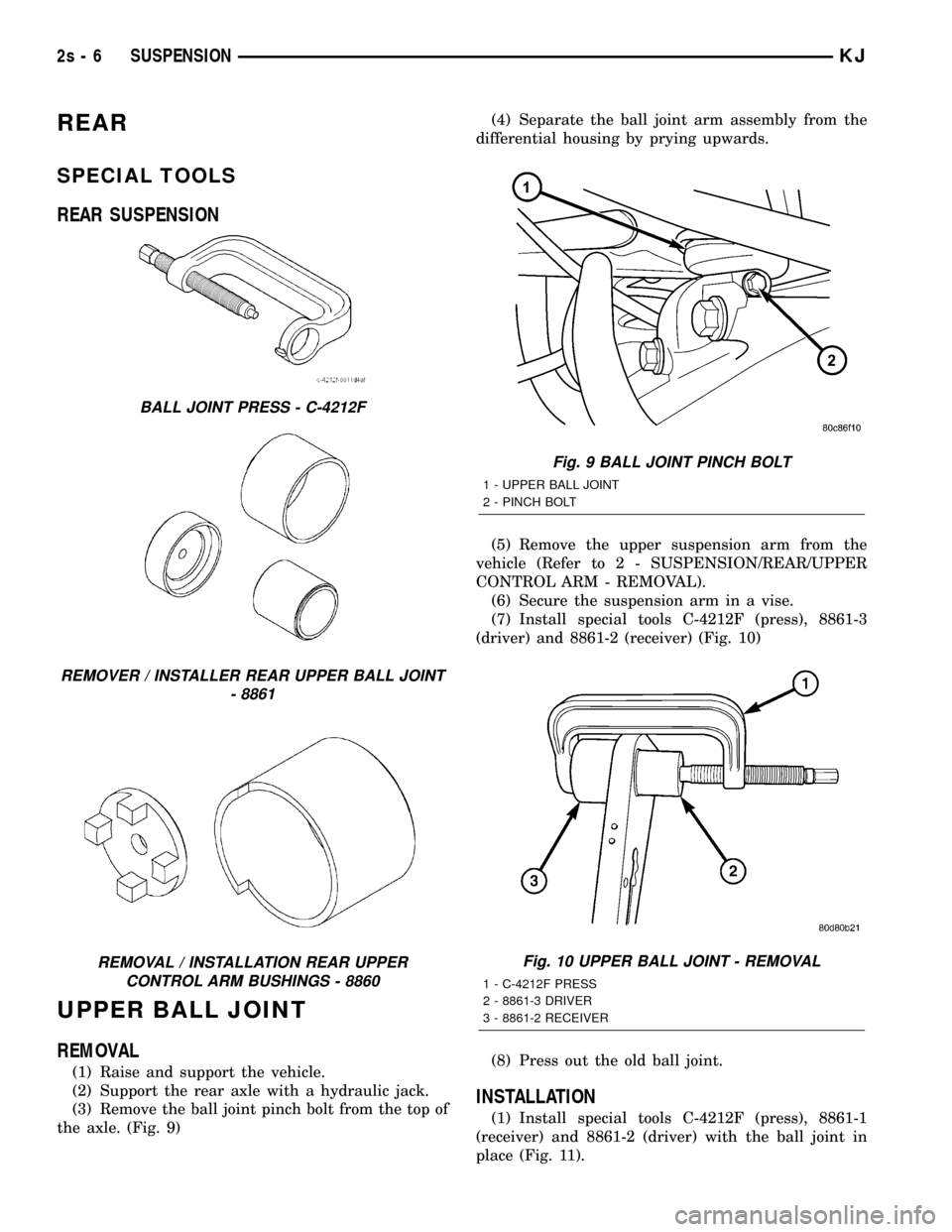
(3) Remove the ball joint pinch bolt from the top of
the axle. (Fig. 9)(4) Separate the ball joint arm assembly from the
differential housing by prying upwards.
(5) Remove the upper suspension arm from the
vehicle (Refer to 2 - SUSPENSION/REAR/UPPER
CONTROL ARM - REMOVAL).
(6) Secure the suspension arm in a vise.
(7) Install special tools C-4212F (press), 8861-3
(driver) and 8861-2 (receiver) (Fig. 10)
(8) Press out the old ball joint.
INSTALLATION
(1) Install special tools C-4212F (press), 8861-1
(receiver) and 8861-2 (driver) with the ball joint in
place (Fig. 11).
BALL JOINT PRESS - C-4212F
REMOVER / INSTALLER REAR UPPER BALL JOINT
- 8861
REMOVAL / INSTALLATION REAR UPPER
CONTROL ARM BUSHINGS - 8860
Fig. 9 BALL JOINT PINCH BOLT
1 - UPPER BALL JOINT
2 - PINCH BOLT
Fig. 10 UPPER BALL JOINT - REMOVAL
1 - C-4212F PRESS
2 - 8861-3 DRIVER
3 - 8861-2 RECEIVER
2s - 6 SUSPENSIONKJ
Page 48 of 1803
(2) Press the ball joint in the upper suspension
arm.
(3) Remove the upper suspension arm from the
vise.
(4) Reinstall the upper suspension arm (Refer to 2
- SUSPENSION/REAR/UPPER CONTROL ARM -
INSTALLATION).
(5) Raise the rear axle with a hydraulic jack to
align the ball joint with the differential housing
bracket.
(6) Insert the ball joint into the differential hous-
ing bracket.
(7) Install the ball joint pinch bolt and tighten to
95 N´m (70 ft. lbs.). (Fig. 9).
(8) Remove the supports and lower the vehicle.
BUSHINGS
REMOVAL
REMOVAL - LOWER SUSPENSION ARM
BUSHING
(1) Remove the lower suspension arm (Refer to 2 -
SUSPENSION/REAR/LOWER CONTROL ARM -
REMOVAL).
(2) Secure the suspension arm in a vise.
NOTE: Extreme pressure lubrication must be used
on the threaded portions of the tool. This will
increase the longevity of the tool and insure proper
operation during the removal and installation pro-
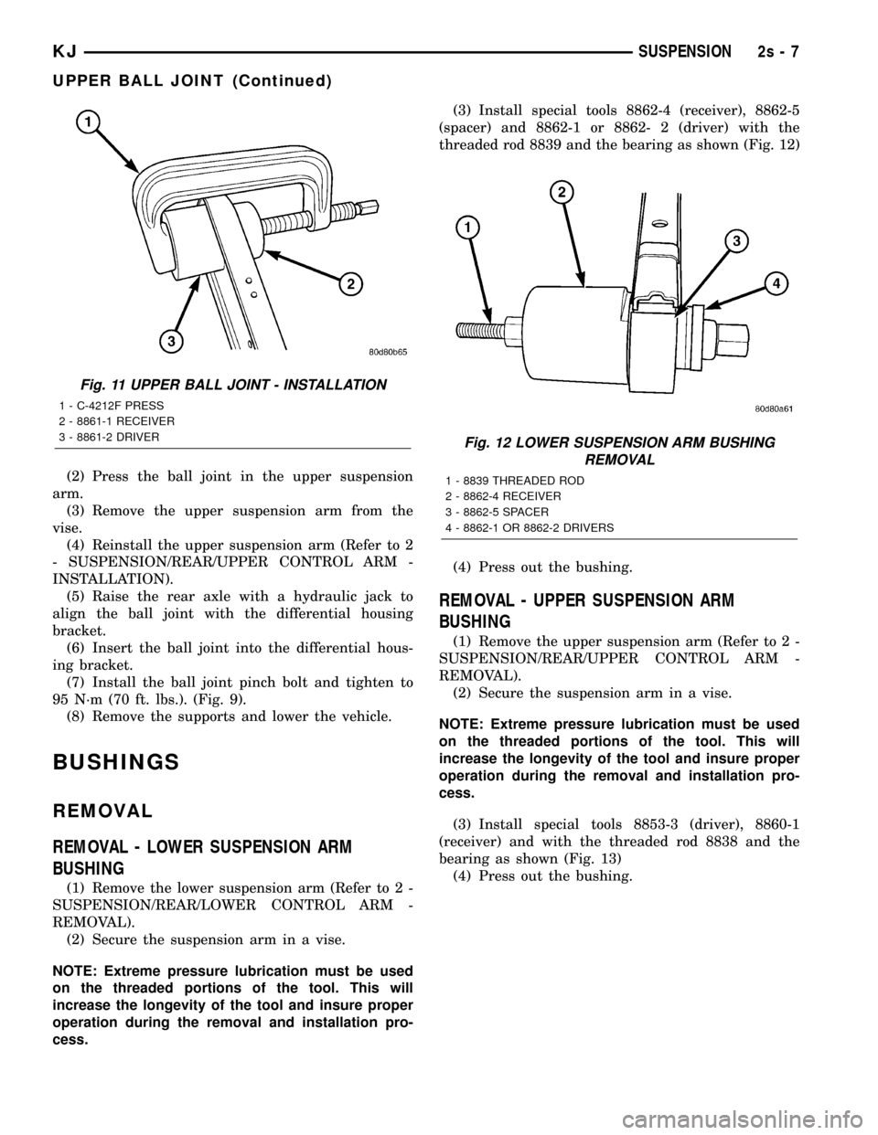
cess.(3) Install special tools 8862-4 (receiver), 8862-5
(spacer) and 8862-1 or 8862- 2 (driver) with the
threaded rod 8839 and the bearing as shown (Fig. 12)
(4) Press out the bushing.
REMOVAL - UPPER SUSPENSION ARM
BUSHING
(1) Remove the upper suspension arm (Refer to 2 -
SUSPENSION/REAR/UPPER CONTROL ARM -
REMOVAL).
(2) Secure the suspension arm in a vise.
NOTE: Extreme pressure lubrication must be used
on the threaded portions of the tool. This will
increase the longevity of the tool and insure proper
operation during the removal and installation pro-
cess.
(3) Install special tools 8853-3 (driver), 8860-1
(receiver) and with the threaded rod 8838 and the
bearing as shown (Fig. 13)
(4) Press out the bushing.
Fig. 11 UPPER BALL JOINT - INSTALLATION
1 - C-4212F PRESS
2 - 8861-1 RECEIVER
3 - 8861-2 DRIVER
Fig. 12 LOWER SUSPENSION ARM BUSHING
REMOVAL
1 - 8839 THREADED ROD
2 - 8862-4 RECEIVER
3 - 8862-5 SPACER
4 - 8862-1 OR 8862-2 DRIVERS
KJSUSPENSION 2s - 7
UPPER BALL JOINT (Continued)
Page 64 of 1803
(8) Place new clamps onto new boot and slide boot
onto the shaft to it's original position.
(9) Apply the rest of lubricant to the C/V joint and
boot.
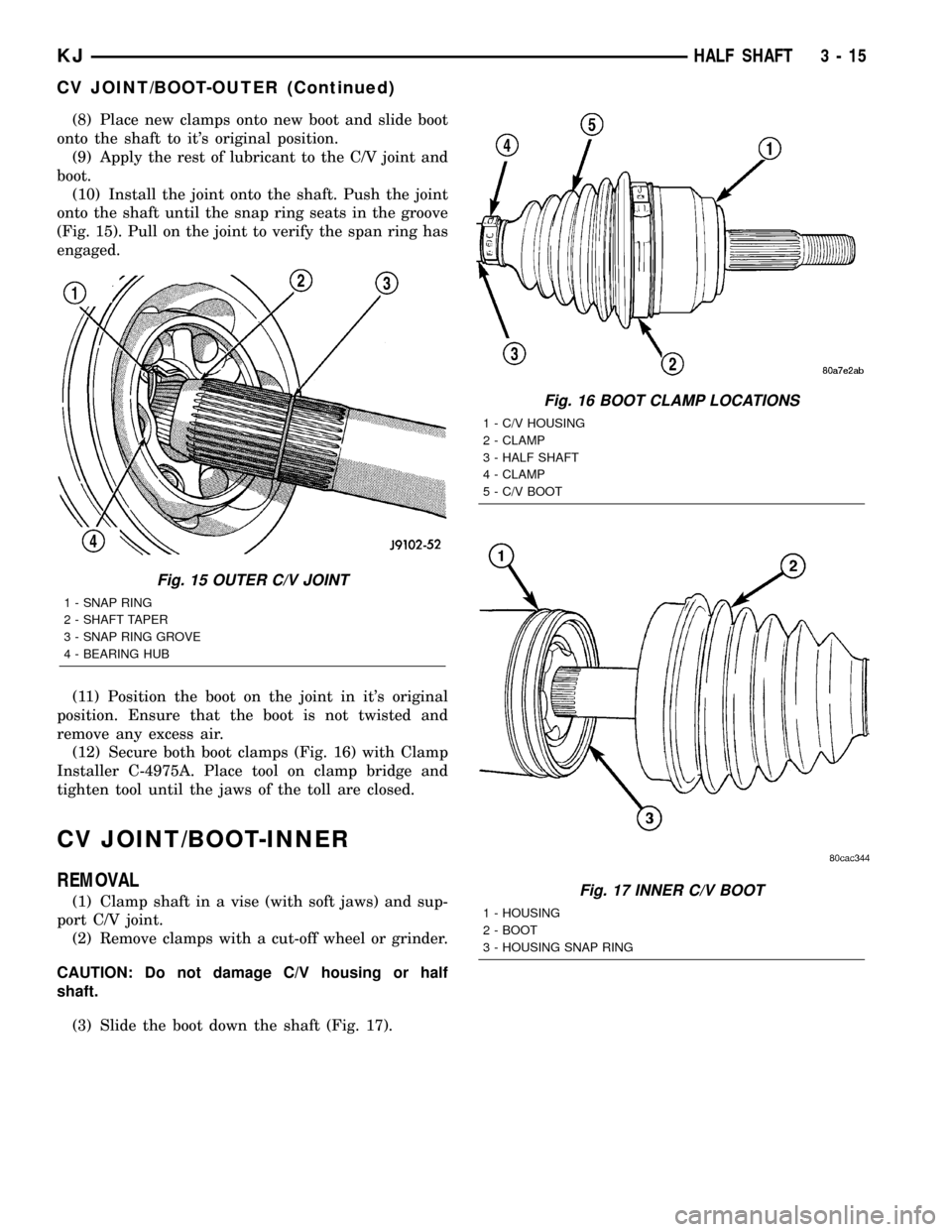
(10) Install the joint onto the shaft. Push the joint
onto the shaft until the snap ring seats in the groove
(Fig. 15). Pull on the joint to verify the span ring has
engaged.
(11) Position the boot on the joint in it's original
position. Ensure that the boot is not twisted and
remove any excess air.
(12) Secure both boot clamps (Fig. 16) with Clamp
Installer C-4975A. Place tool on clamp bridge and
tighten tool until the jaws of the toll are closed.
CV JOINT/BOOT-INNER
REMOVAL
(1) Clamp shaft in a vise (with soft jaws) and sup-
port C/V joint.
(2) Remove clamps with a cut-off wheel or grinder.
CAUTION: Do not damage C/V housing or half
shaft.
(3) Slide the boot down the shaft (Fig. 17).
Fig. 15 OUTER C/V JOINT
1 - SNAP RING
2 - SHAFT TAPER
3 - SNAP RING GROVE
4 - BEARING HUB
Fig. 16 BOOT CLAMP LOCATIONS
1 - C/V HOUSING
2 - CLAMP
3 - HALF SHAFT
4 - CLAMP
5 - C/V BOOT
Fig. 17 INNER C/V BOOT
1 - HOUSING
2 - BOOT
3 - HOUSING SNAP RING
KJHALF SHAFT 3 - 15
CV JOINT/BOOT-OUTER (Continued)
Page 67 of 1803
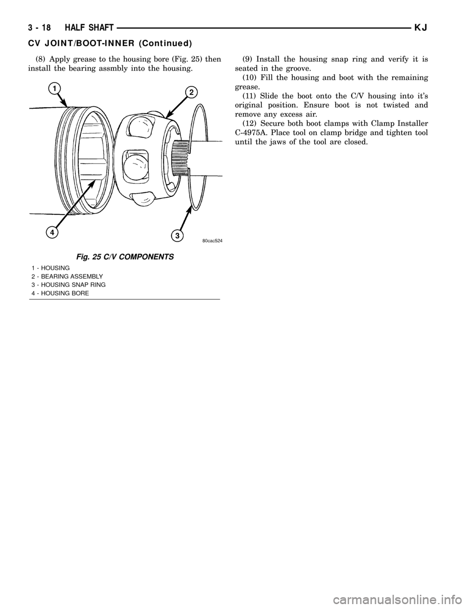
(8) Apply grease to the housing bore (Fig. 25) then
install the bearing assmbly into the housing.(9) Install the housing snap ring and verify it is
seated in the groove.
(10) Fill the housing and boot with the remaining
grease.
(11) Slide the boot onto the C/V housing into it's
original position. Ensure boot is not twisted and
remove any excess air.
(12) Secure both boot clamps with Clamp Installer
C-4975A. Place tool on clamp bridge and tighten tool
until the jaws of the tool are closed.
Fig. 25 C/V COMPONENTS
1 - HOUSING
2 - BEARING ASSEMBLY
3 - HOUSING SNAP RING
4 - HOUSING BORE
3 - 18 HALF SHAFTKJ
CV JOINT/BOOT-INNER (Continued)
Page 76 of 1803
PINION DEPTH MEASUREMENT
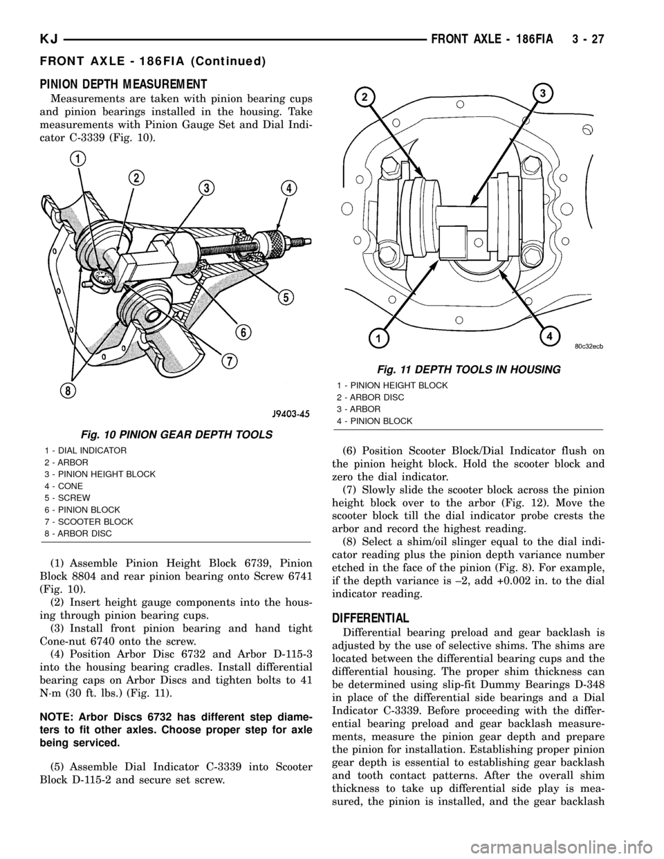
Measurements are taken with pinion bearing cups
and pinion bearings installed in the housing. Take
measurements with Pinion Gauge Set and Dial Indi-
cator C-3339 (Fig. 10).
(1) Assemble Pinion Height Block 6739, Pinion
Block 8804 and rear pinion bearing onto Screw 6741
(Fig. 10).
(2) Insert height gauge components into the hous-
ing through pinion bearing cups.
(3) Install front pinion bearing and hand tight
Cone-nut 6740 onto the screw.
(4) Position Arbor Disc 6732 and Arbor D-115-3
into the housing bearing cradles. Install differential
bearing caps on Arbor Discs and tighten bolts to 41
N´m (30 ft. lbs.) (Fig. 11).
NOTE: Arbor Discs 6732 has different step diame-
ters to fit other axles. Choose proper step for axle
being serviced.
(5) Assemble Dial Indicator C-3339 into Scooter
Block D-115-2 and secure set screw.(6) Position Scooter Block/Dial Indicator flush on
the pinion height block. Hold the scooter block and
zero the dial indicator.
(7) Slowly slide the scooter block across the pinion
height block over to the arbor (Fig. 12). Move the
scooter block till the dial indicator probe crests the
arbor and record the highest reading.
(8) Select a shim/oil slinger equal to the dial indi-
cator reading plus the pinion depth variance number
etched in the face of the pinion (Fig. 8). For example,
if the depth variance is ±2, add +0.002 in. to the dial
indicator reading.
DIFFERENTIAL
Differential bearing preload and gear backlash is
adjusted by the use of selective shims. The shims are
located between the differential bearing cups and the
differential housing. The proper shim thickness can
be determined using slip-fit Dummy Bearings D-348
in place of the differential side bearings and a Dial
Indicator C-3339. Before proceeding with the differ-
ential bearing preload and gear backlash measure-
ments, measure the pinion gear depth and prepare
the pinion for installation. Establishing proper pinion
gear depth is essential to establishing gear backlash
and tooth contact patterns. After the overall shim
thickness to take up differential side play is mea-
sured, the pinion is installed, and the gear backlash
Fig. 10 PINION GEAR DEPTH TOOLS
1 - DIAL INDICATOR
2 - ARBOR
3 - PINION HEIGHT BLOCK
4 - CONE
5 - SCREW
6 - PINION BLOCK
7 - SCOOTER BLOCK
8 - ARBOR DISC
Fig. 11 DEPTH TOOLS IN HOUSING
1 - PINION HEIGHT BLOCK
2 - ARBOR DISC
3 - ARBOR
4 - PINION BLOCK
KJFRONT AXLE - 186FIA 3 - 27
FRONT AXLE - 186FIA (Continued)
Page 103 of 1803
REMOVAL
(1) Raise and support the vehicle.
(2) Position a lift/jack under the axle and secure
axle to device.
(3) Remove wheels and tires.
(4) Mark propeller shaft and pinion yoke for
installation reference.
(5) Remove propeller shaft and suspend under the
vehicle.
(6) Remove brake drums, parking brake cables and
speed sensor from the axle.
(7) Disconnect the brake hose at the body junction
block.
(8) Remove brakes and backing plates.
(9) Remove vent hose from the axle shaft tube.
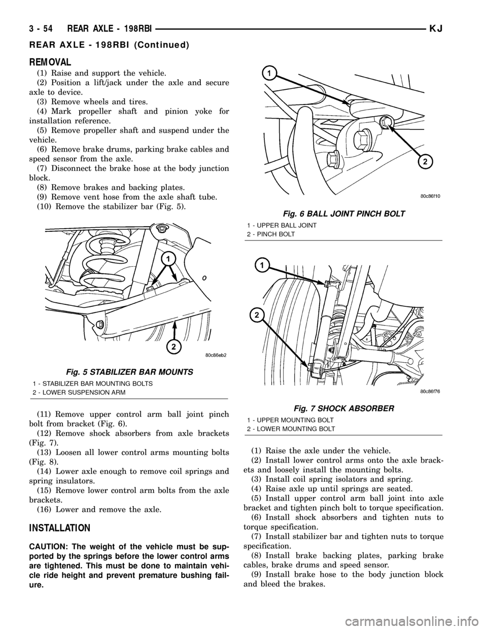
(10) Remove the stabilizer bar (Fig. 5).
(11) Remove upper control arm ball joint pinch
bolt from bracket (Fig. 6).
(12) Remove shock absorbers from axle brackets
(Fig. 7).
(13) Loosen all lower control arms mounting bolts
(Fig. 8).
(14) Lower axle enough to remove coil springs and
spring insulators.
(15) Remove lower control arm bolts from the axle
brackets.
(16) Lower and remove the axle.
INSTALLATION
CAUTION: The weight of the vehicle must be sup-
ported by the springs before the lower control arms
are tightened. This must be done to maintain vehi-
cle ride height and prevent premature bushing fail-
ure.(1) Raise the axle under the vehicle.
(2) Install lower control arms onto the axle brack-
ets and loosely install the mounting bolts.
(3) Install coil spring isolators and spring.
(4) Raise axle up until springs are seated.
(5) Install upper control arm ball joint into axle
bracket and tighten pinch bolt to torque specification.
(6) Install shock absorbers and tighten nuts to
torque specification.
(7) Install stabilizer bar and tighten nuts to torque
specification.
(8) Install brake backing plates, parking brake
cables, brake drums and speed sensor.
(9) Install brake hose to the body junction block
and bleed the brakes.
Fig. 5 STABILIZER BAR MOUNTS
1 - STABILIZER BAR MOUNTING BOLTS
2 - LOWER SUSPENSION ARM
Fig. 6 BALL JOINT PINCH BOLT
1 - UPPER BALL JOINT
2 - PINCH BOLT
Fig. 7 SHOCK ABSORBER
1 - UPPER MOUNTING BOLT
2 - LOWER MOUNTING BOLT
3 - 54 REAR AXLE - 198RBIKJ
REAR AXLE - 198RBI (Continued)
Page 106 of 1803
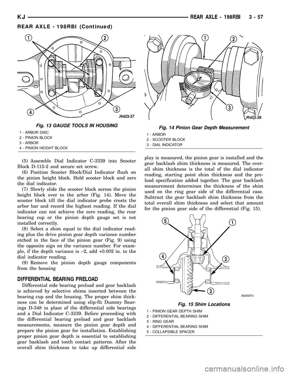
(5) Assemble Dial Indicator C-3339 into Scooter
Block D-115-2 and secure set screw.
(6) Position Scooter Block/Dial Indicator flush on
the pinion height block. Hold scooter block and zero
the dial indicator.
(7) Slowly slide the scooter block across the pinion
height block over to the arbor (Fig. 14). Move the
scooter block till the dial indicator probe crests the
arbor bar and record the highest reading. If the dial
indicator can not achieve the zero reading, the rear
bearing cup or the pinion depth gauge set is not
installed correctly.
(8) Select a shim equal to the dial indicator read-
ing plus the drive pinion gear depth variance number
etched in the face of the pinion gear (Fig. 9) using
the opposite sign on the variance number. For exam-
ple, if the depth variance is ±2, add +0.002 in. to the
dial indicator reading.
(9) Remove the pinion depth gauge components
from the housing
DIFFERENTIAL BEARING PRELOAD
Differential side bearing preload and gear backlash
is achieved by selective shims inserted between the
bearing cup and the housing. The proper shim thick-
ness can be determined using slip-fit Dummy Bear-
ings D-348 in place of the differential side bearings
and a Dial Indicator C-3339. Before proceeding with
the differential bearing preload and gear backlash
measurements, measure the pinion gear depth and
prepare the pinion gear for installation. Establishing
proper pinion gear depth is essential to establishing
gear backlash and tooth contact patterns. After the
overall shim thickness to take up differential sideplay is measured, the pinion gear is installed and the
gear backlash shim thickness is measured. The over-
all shim thickness is the total of the dial indicator
reading, starting point shim thickness and the pre-
load specification added together. The gear backlash
measurement determines the thickness of the shim
used on the ring gear side of the differential case.
Subtract the gear backlash shim thickness from the
total overall shim thickness and select that amount
for the pinion gear side of the differential (Fig. 15).
Fig. 13 GAUGE TOOLS IN HOUSING
1 - ARBOR DISC
2 - PINION BLOCK
3 - ARBOR
4 - PINION HEIGHT BLOCKFig. 14 Pinion Gear Depth Measurement
1 - ARBOR
2 - SCOOTER BLOCK
3 - DIAL INDICATOR
Fig. 15 Shim Locations
1 - PINION GEAR DEPTH SHIM
2 - DIFFERENTIAL BEARING SHIM
3 - RING GEAR
4 - DIFFERENTIAL BEARING SHIM
5 - COLLAPSIBLE SPACER
KJREAR AXLE - 198RBI 3 - 57
REAR AXLE - 198RBI (Continued)
Page 126 of 1803
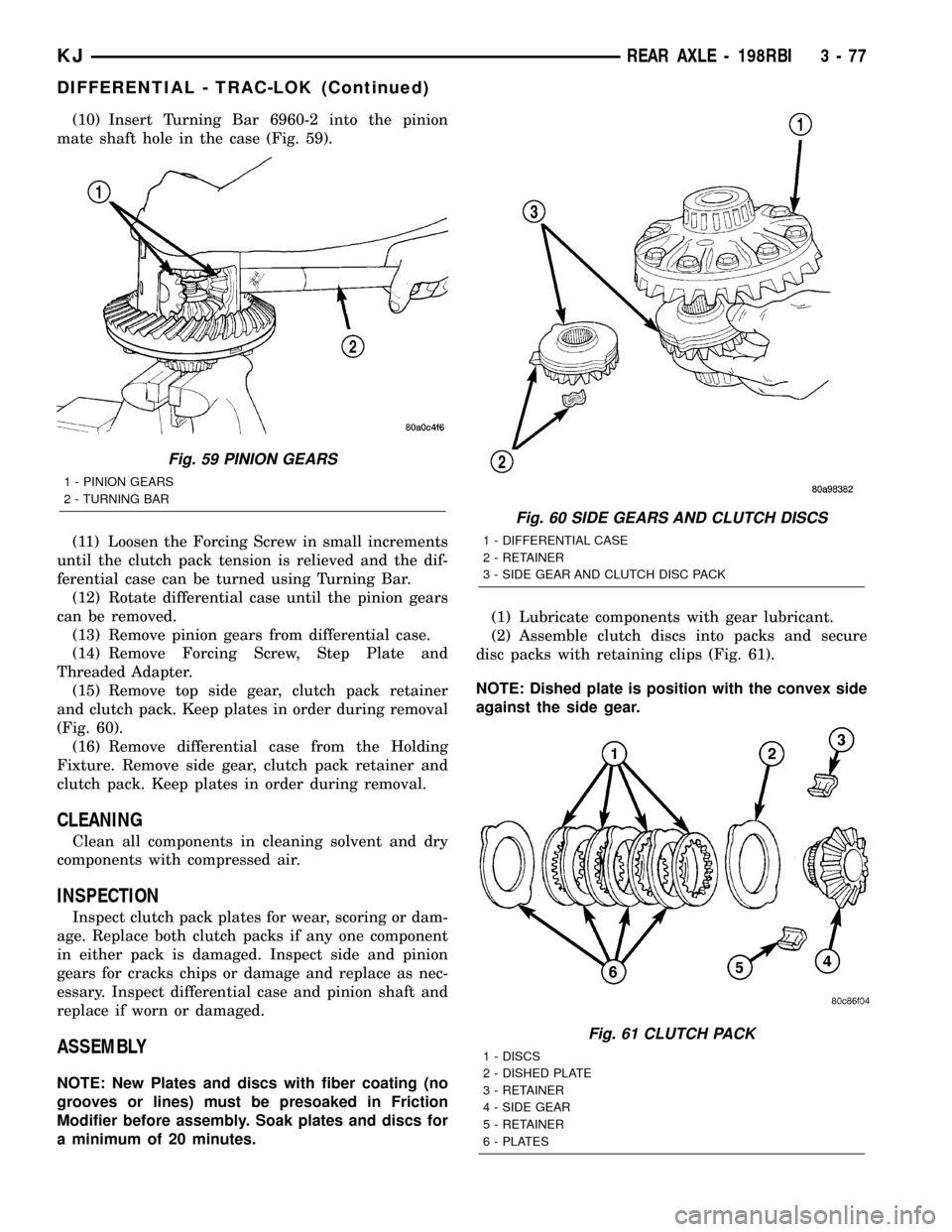
(10) Insert Turning Bar 6960-2 into the pinion
mate shaft hole in the case (Fig. 59).
(11) Loosen the Forcing Screw in small increments
until the clutch pack tension is relieved and the dif-
ferential case can be turned using Turning Bar.
(12) Rotate differential case until the pinion gears
can be removed.
(13) Remove pinion gears from differential case.
(14) Remove Forcing Screw, Step Plate and
Threaded Adapter.
(15) Remove top side gear, clutch pack retainer
and clutch pack. Keep plates in order during removal
(Fig. 60).
(16) Remove differential case from the Holding
Fixture. Remove side gear, clutch pack retainer and
clutch pack. Keep plates in order during removal.
CLEANING
Clean all components in cleaning solvent and dry
components with compressed air.
INSPECTION
Inspect clutch pack plates for wear, scoring or dam-
age. Replace both clutch packs if any one component
in either pack is damaged. Inspect side and pinion
gears for cracks chips or damage and replace as nec-
essary. Inspect differential case and pinion shaft and
replace if worn or damaged.
ASSEMBLY
NOTE: New Plates and discs with fiber coating (no
grooves or lines) must be presoaked in Friction
Modifier before assembly. Soak plates and discs for
a minimum of 20 minutes.(1) Lubricate components with gear lubricant.
(2) Assemble clutch discs into packs and secure
disc packs with retaining clips (Fig. 61).
NOTE: Dished plate is position with the convex side
against the side gear.
Fig. 59 PINION GEARS
1 - PINION GEARS
2 - TURNING BAR
Fig. 60 SIDE GEARS AND CLUTCH DISCS
1 - DIFFERENTIAL CASE
2 - RETAINER
3 - SIDE GEAR AND CLUTCH DISC PACK
Fig. 61 CLUTCH PACK
1 - DISCS
2 - DISHED PLATE
3 - RETAINER
4 - SIDE GEAR
5 - RETAINER
6 - PLATES
KJREAR AXLE - 198RBI 3 - 77
DIFFERENTIAL - TRAC-LOK (Continued)
Page 140 of 1803
REMOVAL
(1) Raise and support the vehicle.
(2) Position a lift/jack under the axle and secure
axle to device.
(3) Remove wheels and tires.
(4) Mark propeller shaft and pinion yoke for
installation reference.
(5) Remove propeller shaft and suspend under the
vehicle.
(6) Remove brake drums, parking brake cables and
speed sensor from the axle.
(7) Disconnect the brake hose at the body junction
block.
(8) Remove brakes and backing plates.
(9) Remove vent hose from the axle shaft tube.
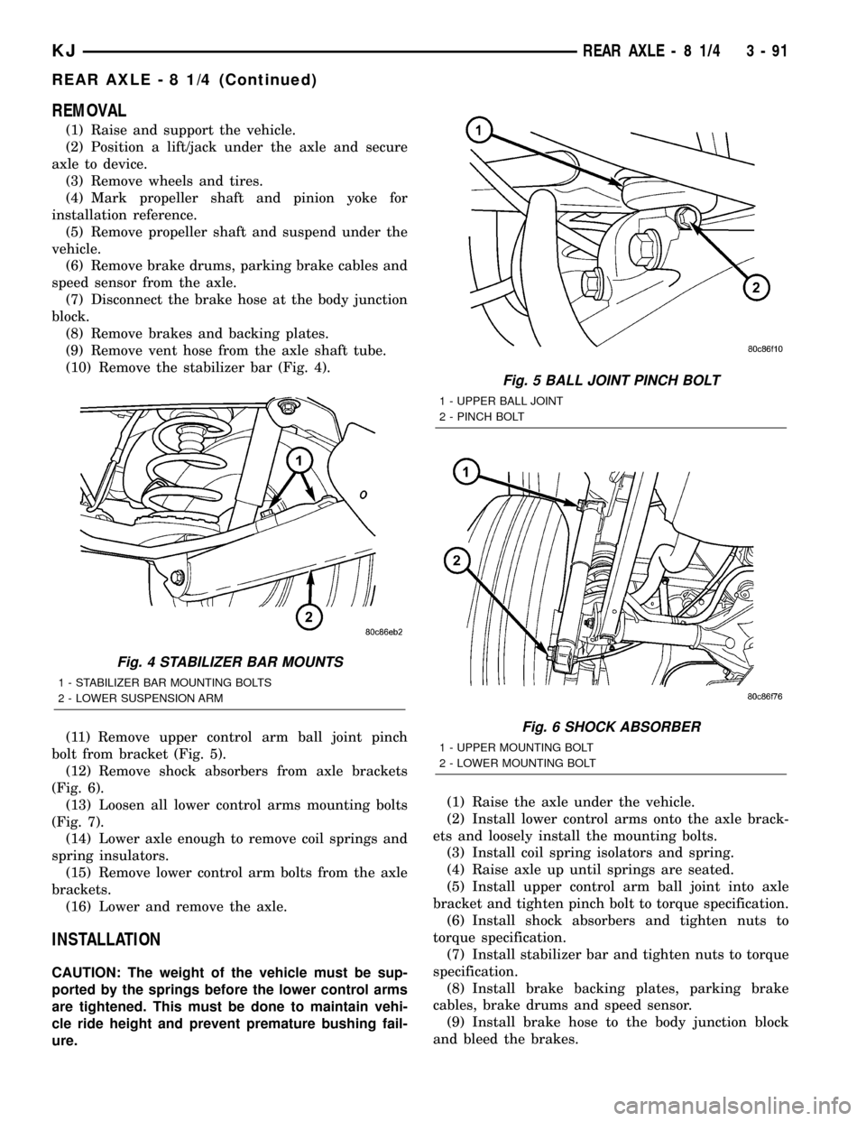
(10) Remove the stabilizer bar (Fig. 4).
(11) Remove upper control arm ball joint pinch
bolt from bracket (Fig. 5).
(12) Remove shock absorbers from axle brackets
(Fig. 6).
(13) Loosen all lower control arms mounting bolts
(Fig. 7).
(14) Lower axle enough to remove coil springs and
spring insulators.
(15) Remove lower control arm bolts from the axle
brackets.
(16) Lower and remove the axle.
INSTALLATION
CAUTION: The weight of the vehicle must be sup-
ported by the springs before the lower control arms
are tightened. This must be done to maintain vehi-
cle ride height and prevent premature bushing fail-
ure.(1) Raise the axle under the vehicle.
(2) Install lower control arms onto the axle brack-
ets and loosely install the mounting bolts.
(3) Install coil spring isolators and spring.
(4) Raise axle up until springs are seated.
(5) Install upper control arm ball joint into axle
bracket and tighten pinch bolt to torque specification.
(6) Install shock absorbers and tighten nuts to
torque specification.
(7) Install stabilizer bar and tighten nuts to torque
specification.
(8) Install brake backing plates, parking brake
cables, brake drums and speed sensor.
(9) Install brake hose to the body junction block
and bleed the brakes.
Fig. 4 STABILIZER BAR MOUNTS
1 - STABILIZER BAR MOUNTING BOLTS
2 - LOWER SUSPENSION ARM
Fig. 5 BALL JOINT PINCH BOLT
1 - UPPER BALL JOINT
2 - PINCH BOLT
Fig. 6 SHOCK ABSORBER
1 - UPPER MOUNTING BOLT
2 - LOWER MOUNTING BOLT
KJREAR AXLE - 8 1/4 3 - 91
REAR AXLE - 8 1/4 (Continued)