check oil JEEP LIBERTY 2002 KJ / 1.G User Guide
[x] Cancel search | Manufacturer: JEEP, Model Year: 2002, Model line: LIBERTY, Model: JEEP LIBERTY 2002 KJ / 1.GPages: 1803, PDF Size: 62.3 MB
Page 216 of 1803
COOLING
TABLE OF CONTENTS
page page
COOLING
DESCRIPTION
DESCRIPTION - COOLING SYSTEM 3.7L
ENGINE..............................1
DESCRIPTION - COOLING SYSTEM
ROUTING 3.7L ENGINE..................2
DESCRIPTION - HOSE CLAMPS...........2
OPERATION
OPERATION - COOLING SYSTEM.........2
OPERATION - HOSE CLAMPS............3
DIAGNOSIS AND TESTING
DIAGNOSIS AND TESTING - ON-BOARD
DIAGNOSTICS (OBD)...................3
DIAGNOSIS AND TESTING - PRELIMINARY
CHECKS.............................3
DIAGNOSIS AND TESTING - COOLING
SYSTEM LEAKS.......................4DIAGNOSIS AND TESTING - COOLING
SYSTEM DIAGNOSIS CHART.............6
STANDARD PROCEDURE
STANDARD PROCEDURE - DRAINING
COOLING SYSTEM 3.7L ENGINE.........12
STANDARD PROCEDURE - REFILLING
COOLING SYSTEM 3.7L ENGINE.........12
STANDARD PROCEDURE - COOLING
SYSTEM - REVERSE FLUSHING..........12
SPECIFICATIONS
TORQUE............................13
SPECIAL TOOLS
COOLING...........................14
ACCESSORY DRIVE......................15
ENGINE...............................19
TRANSMISSION.........................32
COOLING
DESCRIPTION
DESCRIPTION - COOLING SYSTEM 3.7L
ENGINE
The cooling system consists of the following items:
²Electric cooling fan - Standard.
²Electric cooling fan and mechanical thermal vis-
cous fan with low disengaged - Heavy duty cooling
only²Radiator
²Hot bottle pressure cap
²Thermostat
²Coolant reserve/overflow system
²Radiator in-tank transmission oil cooler (if
equipped with an automatic transmission)
²Coolant
²Water pump
²Hoses and hose clamps
KJCOOLING 7 - 1
Page 219 of 1803
DIAGNOSIS AND TESTING - COOLING SYSTEM
LEAKS
ULTRAVIOLET LIGHT METHOD
A leak detection additive is available through the
parts department that can be added to cooling sys-
tem. The additive is highly visible under ultraviolet
light (black light). Pour one ounce of additive into
cooling system. Place heater control unit in HEAT
position. Start and operate engine until radiator
upper hose is warm to touch. Aim the commercially
available black light tool at components to be
checked. If leaks are present, black light will cause
additive to glow a bright green color.
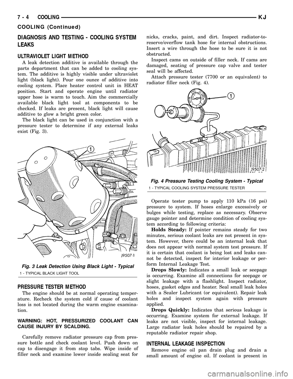
The black light can be used in conjunction with a
pressure tester to determine if any external leaks
exist (Fig. 3).
PRESSURE TESTER METHOD
The engine should be at normal operating temper-
ature. Recheck the system cold if cause of coolant
loss is not located during the warm engine examina-
tion.
WARNING: HOT, PRESSURIZED COOLANT CAN
CAUSE INJURY BY SCALDING.
Carefully remove radiator pressure cap from pres-
sure bottle and check coolant level. Push down on
cap to disengage it from stop tabs. Wipe inside of
filler neck and examine lower inside sealing seat fornicks, cracks, paint, and dirt. Inspect radiator-to-
reserve/overflow tank hose for internal obstructions.
Insert a wire through the hose to be sure it is not
obstructed.
Inspect cams on outside of filler neck. If cams are
damaged, seating of pressure cap valve and tester
seal will be affected.
Attach pressure tester (7700 or an equivalent) to
radiator filler neck (Fig. 4).
Operate tester pump to apply 110 kPa (16 psi)
pressure to system. If hoses enlarge excessively or
bulges while testing, replace as necessary. Observe
gauge pointer and determine condition of cooling sys-
tem according to following criteria:
Holds Steady:If pointer remains steady for two
minutes, serious coolant leaks are not present in sys-
tem. However, there could be an internal leak that
does not appear with normal system test pressure. If
it is certain that coolant is being lost and leaks can-
not be detected, inspect for interior leakage or per-
form Internal Leakage Test.
Drops Slowly:Indicates a small leak or seepage
is occurring. Examine all connections for seepage or
slight leakage with a flashlight. Inspect radiator,
hoses, gasket edges and heater. Seal small leak holes
with a Sealer Lubricant (or equivalent). Repair leak
holes and inspect system again with pressure
applied.
Drops Quickly:Indicates that serious leakage is
occurring. Examine system for external leakage. If
leaks are not visible, inspect for internal leakage.
Large radiator leak holes should be repaired by a
reputable radiator repair shop.
INTERNAL LEAKAGE INSPECTION
Remove engine oil pan drain plug and drain a
small amount of engine oil. If coolant is present in
Fig. 3 Leak Detection Using Black Light - Typical
1 - TYPICAL BLACK LIGHT TOOL
Fig. 4 Pressure Testing Cooling System - Typical
1 - TYPICAL COOLING SYSTEM PRESSURE TESTER
7 - 4 COOLINGKJ
COOLING (Continued)
Page 220 of 1803
the pan, it will drain first because it is heavier than
oil. An alternative method is to operate engine for a
short period to churn the oil. After this is done,
remove engine dipstick and inspect for water glob-
ules. Also inspect transmission dipstick for water
globules and transmission fluid cooler for leakage.
WARNING: WITH RADIATOR PRESSURE TESTER
TOOL INSTALLED ON RADIATOR, DO NOT ALLOW
PRESSURE TO EXCEED 124 KPA (18 PSI). PRES-
SURE WILL BUILD UP QUICKLY IF A COMBUSTION
LEAK IS PRESENT. TO RELEASE PRESSURE,
ROCK TESTER FROM SIDE TO SIDE. WHEN
REMOVING TESTER, DO NOT TURN TESTER MORE
THAN 1/2 TURN IF SYSTEM IS UNDER PRESSURE.
Operate engine without pressure cap on radiator
until thermostat opens. Attach a Pressure Tester to
filler neck. If pressure builds up quickly it indicates a
combustion leak exists. This is usually the result of a
cylinder head gasket leak or crack in engine. Repair
as necessary.
If there is not an immediate pressure increase,
pump the Pressure Tester. Do this until indicated
pressure is within system range of 110 kPa (16 psi).
Fluctuation of gauge pointer indicates compression or
combustion leakage into cooling system.
Because the vehicle is equipped with a catalytic
converter,do notremove spark plug cables or short
out cylinders to isolate compression leak.
If the needle on dial of pressure tester does not
fluctuate, race engine a few times to check for an
abnormal amount of coolant or steam. This would be
emitting from exhaust pipe. Coolant or steam from
exhaust pipe may indicate a faulty cylinder head gas-
ket, cracked engine cylinder block or cylinder head.A convenient check for exhaust gas leakage into
cooling system is provided by a commercially avail-
able Block Leak Check tool. Follow manufacturers
instructions when using this product.
COMBUSTION LEAKAGE TEST - WITHOUT
PRESSURE TESTER
DO NOT WASTE reusable coolant. If solution is
clean, drain coolant into a clean container for reuse.
WARNING: DO NOT REMOVE CYLINDER BLOCK
DRAIN PLUGS OR LOOSEN RADIATOR DRAIN-
COCK WITH SYSTEM HOT AND UNDER PRESSURE.
SERIOUS BURNS FROM COOLANT CAN OCCUR.
Drain sufficient coolant to allow thermostat
removal. (Refer to 7 - COOLING/ENGINE/ENGINE
COOLANT THERMOSTAT - REMOVAL). Remove
accessory drive belt (Refer to 7 - COOLING/ACCES-
SORY DRIVE/DRIVE BELTS - REMOVAL).
Add coolant to radiator to bring level to within 6.3
mm (1/4 in) of top of thermostat housing.
CAUTION: Avoid overheating. Do not operate
engine for an excessive period of time. Open drain-
cock immediately after test to eliminate boil over.
Start engine and accelerate rapidly three times, to
approximately 3000 rpm while observing coolant. If
internal engine combustion gases are leaking into
cooling system, bubbles will appear in coolant. If bub-
bles do not appear, internal combustion gas leakage
is not present.
KJCOOLING 7 - 5
COOLING (Continued)
Page 222 of 1803
CONDITION POSSIBLE CAUSES CORRECTION
5. Pressure cap not installed tightly.
If cap is loose, boiling point of
coolant will be lowered. Also refer
to the following Step 6.5. Tighten cap
6. Poor seals at the radiator cap. 6. (a) Check condition of cap and
cap seals. (Refer to 7 - COOLING/
ENGINE/RADIATOR PRESSURE
CAP - DIAGNOSIS AND TESTING).
(b) Check condition of radiator filler
neck. If neck is bent or damaged,
replace radiator.
7. Coolant not flowing through
system.7. (a) Check condition of pressure
bottle cap and cap seals. (Refer to
7 - COOLING/ENGINE/RADIATOR
PRESSURE CAP - DIAGNOSIS
AND TESTING).
(b) Check condition of radiator vent
nipple. If neck is damaged, replace
radiator.
(c) Check condition of the hose from
the radiator to the coolant tank. It
should fit tight at both ends without
any kinks or tears. Replace hose if
necessary.
(d) Check pressure bottle/overflow
tank and tanks hoses for blockage.
Repair as necessary.
8. Incorrect coolant concentration 8. Check coolant. (Refer to 7 -
COOLING/ENGINE/COOLANT -
DESCRIPTION) for correct
coolant/water mixture ratio.
9. Fan installed backwards on
viscous drive.9. Mount fan on drive correctly.
10. Radiator or A/C condenser fins
are dirty or clogged.10. Remove insects and debris.
(Refer to 7 - COOLING/ENGINE/
RADIATOR - CLEANING).
11. Radiator core is corroded or
plugged.11. Have radiator re-cored or
replaced.
12. Fuel or ignition system
problems.12. Refer to FUEL and /or
IGNITION CONTROL for diagnosis.
13. Dragging brakes. 13. Check and correct as
necessary. (Refer to 5 - BRAKES -
DIAGNOSIS AND TESTING) for
correct procedures.
14. Bug screen or cardboard is
being used, reducing airflow.14. Remove bug screen or
cardboard.
KJCOOLING 7 - 7
COOLING (Continued)
Page 224 of 1803
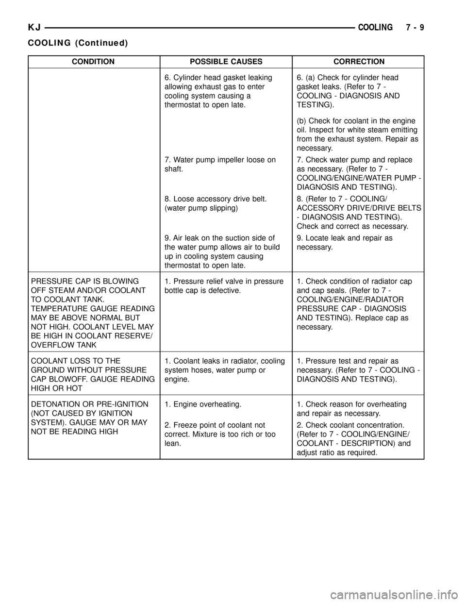
CONDITION POSSIBLE CAUSES CORRECTION
6. Cylinder head gasket leaking
allowing exhaust gas to enter
cooling system causing a
thermostat to open late.6. (a) Check for cylinder head
gasket leaks. (Refer to 7 -
COOLING - DIAGNOSIS AND
TESTING).
(b) Check for coolant in the engine
oil. Inspect for white steam emitting
from the exhaust system. Repair as
necessary.
7. Water pump impeller loose on
shaft.7. Check water pump and replace
as necessary. (Refer to 7 -
COOLING/ENGINE/WATER PUMP -
DIAGNOSIS AND TESTING).
8. Loose accessory drive belt.
(water pump slipping)8. (Refer to 7 - COOLING/
ACCESSORY DRIVE/DRIVE BELTS
- DIAGNOSIS AND TESTING).
Check and correct as necessary.
9. Air leak on the suction side of
the water pump allows air to build
up in cooling system causing
thermostat to open late.9. Locate leak and repair as
necessary.
PRESSURE CAP IS BLOWING
OFF STEAM AND/OR COOLANT
TO COOLANT TANK.
TEMPERATURE GAUGE READING
MAY BE ABOVE NORMAL BUT
NOT HIGH. COOLANT LEVEL MAY
BE HIGH IN COOLANT RESERVE/
OVERFLOW TANK1. Pressure relief valve in pressure
bottle cap is defective.1. Check condition of radiator cap
and cap seals. (Refer to 7 -
COOLING/ENGINE/RADIATOR
PRESSURE CAP - DIAGNOSIS
AND TESTING). Replace cap as
necessary.
COOLANT LOSS TO THE
GROUND WITHOUT PRESSURE
CAP BLOWOFF. GAUGE READING
HIGH OR HOT1. Coolant leaks in radiator, cooling
system hoses, water pump or
engine.1. Pressure test and repair as
necessary. (Refer to 7 - COOLING -
DIAGNOSIS AND TESTING).
DETONATION OR PRE-IGNITION
(NOT CAUSED BY IGNITION
SYSTEM). GAUGE MAY OR MAY
NOT BE READING HIGH1. Engine overheating. 1. Check reason for overheating
and repair as necessary.
2. Freeze point of coolant not
correct. Mixture is too rich or too
lean.2. Check coolant concentration.
(Refer to 7 - COOLING/ENGINE/
COOLANT - DESCRIPTION) and
adjust ratio as required.
KJCOOLING 7 - 9
COOLING (Continued)
Page 231 of 1803
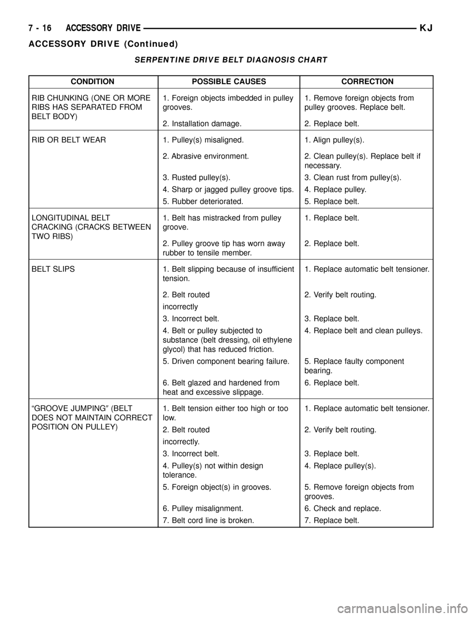
SERPENTINE DRIVE BELT DIAGNOSIS CHART
CONDITION POSSIBLE CAUSES CORRECTION
RIB CHUNKING (ONE OR MORE
RIBS HAS SEPARATED FROM
BELT BODY)1. Foreign objects imbedded in pulley
grooves.1. Remove foreign objects from
pulley grooves. Replace belt.
2. Installation damage. 2. Replace belt.
RIB OR BELT WEAR 1. Pulley(s) misaligned. 1. Align pulley(s).
2. Abrasive environment. 2. Clean pulley(s). Replace belt if
necessary.
3. Rusted pulley(s). 3. Clean rust from pulley(s).
4. Sharp or jagged pulley groove tips. 4. Replace pulley.
5. Rubber deteriorated. 5. Replace belt.
LONGITUDINAL BELT
CRACKING (CRACKS BETWEEN
TWO RIBS)1. Belt has mistracked from pulley
groove.1. Replace belt.
2. Pulley groove tip has worn away
rubber to tensile member.2. Replace belt.
BELT SLIPS 1. Belt slipping because of insufficient
tension.1. Replace automatic belt tensioner.
2. Belt routed 2. Verify belt routing.
incorrectly
3. Incorrect belt. 3. Replace belt.
4. Belt or pulley subjected to
substance (belt dressing, oil ethylene
glycol) that has reduced friction.4. Replace belt and clean pulleys.
5. Driven component bearing failure. 5. Replace faulty component
bearing.
6. Belt glazed and hardened from
heat and excessive slippage.6. Replace belt.
ªGROOVE JUMPING9(BELT
DOES NOT MAINTAIN CORRECT
POSITION ON PULLEY)1. Belt tension either too high or too
low.1. Replace automatic belt tensioner.
2. Belt routed 2. Verify belt routing.
incorrectly.
3. Incorrect belt. 3. Replace belt.
4. Pulley(s) not within design
tolerance.4. Replace pulley(s).
5. Foreign object(s) in grooves. 5. Remove foreign objects from
grooves.
6. Pulley misalignment. 6. Check and replace.
7. Belt cord line is broken. 7. Replace belt.
7 - 16 ACCESSORY DRIVEKJ
ACCESSORY DRIVE (Continued)
Page 234 of 1803
ENGINE
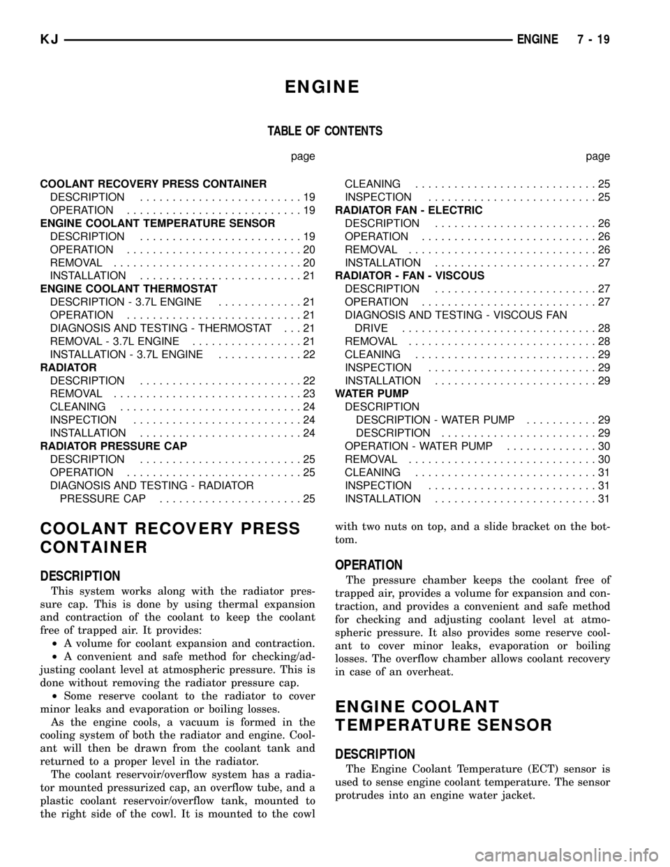
TABLE OF CONTENTS
page page
COOLANT RECOVERY PRESS CONTAINER
DESCRIPTION.........................19
OPERATION...........................19
ENGINE COOLANT TEMPERATURE SENSOR
DESCRIPTION.........................19
OPERATION...........................20
REMOVAL.............................20
INSTALLATION.........................21
ENGINE COOLANT THERMOSTAT
DESCRIPTION - 3.7L ENGINE.............21
OPERATION...........................21
DIAGNOSIS AND TESTING - THERMOSTAT . . . 21
REMOVAL - 3.7L ENGINE.................21
INSTALLATION - 3.7L ENGINE.............22
RADIATOR
DESCRIPTION.........................22
REMOVAL.............................23
CLEANING............................24
INSPECTION..........................24
INSTALLATION.........................24
RADIATOR PRESSURE CAP
DESCRIPTION.........................25
OPERATION...........................25
DIAGNOSIS AND TESTING - RADIATOR
PRESSURE CAP......................25CLEANING............................25
INSPECTION..........................25
RADIATOR FAN - ELECTRIC
DESCRIPTION.........................26
OPERATION...........................26
REMOVAL.............................26
INSTALLATION.........................27
RADIATOR - FAN - VISCOUS
DESCRIPTION.........................27
OPERATION...........................27
DIAGNOSIS AND TESTING - VISCOUS FAN
DRIVE..............................28
REMOVAL.............................28
CLEANING............................29
INSPECTION..........................29
INSTALLATION.........................29
WATER PUMP
DESCRIPTION
DESCRIPTION - WATER PUMP...........29
DESCRIPTION........................29
OPERATION - WATER PUMP..............30
REMOVAL.............................30
CLEANING............................31
INSPECTION..........................31
INSTALLATION.........................31
COOLANT RECOVERY PRESS
CONTAINER
DESCRIPTION
This system works along with the radiator pres-
sure cap. This is done by using thermal expansion
and contraction of the coolant to keep the coolant
free of trapped air. It provides:
²A volume for coolant expansion and contraction.
²A convenient and safe method for checking/ad-
justing coolant level at atmospheric pressure. This is
done without removing the radiator pressure cap.
²Some reserve coolant to the radiator to cover
minor leaks and evaporation or boiling losses.
As the engine cools, a vacuum is formed in the
cooling system of both the radiator and engine. Cool-
ant will then be drawn from the coolant tank and
returned to a proper level in the radiator.
The coolant reservoir/overflow system has a radia-
tor mounted pressurized cap, an overflow tube, and a
plastic coolant reservoir/overflow tank, mounted to
the right side of the cowl. It is mounted to the cowlwith two nuts on top, and a slide bracket on the bot-
tom.
OPERATION
The pressure chamber keeps the coolant free of
trapped air, provides a volume for expansion and con-
traction, and provides a convenient and safe method
for checking and adjusting coolant level at atmo-
spheric pressure. It also provides some reserve cool-
ant to cover minor leaks, evaporation or boiling
losses. The overflow chamber allows coolant recovery
in case of an overheat.
ENGINE COOLANT
TEMPERATURE SENSOR
DESCRIPTION
The Engine Coolant Temperature (ECT) sensor is
used to sense engine coolant temperature. The sensor
protrudes into an engine water jacket.
KJENGINE 7 - 19
Page 240 of 1803
RADIATOR PRESSURE CAP
DESCRIPTION
The cooling system cap is located on the coolant
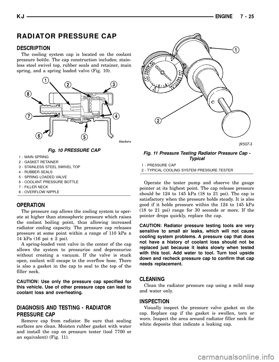
pressure bottle. The cap construction includes; stain-
less steel swivel top, rubber seals and retainer, main
spring, and a spring loaded valve (Fig. 10).
OPERATION
The pressure cap allows the cooling system to oper-
ate at higher than atmospheric pressure which raises
the coolant boiling point, thus allowing increased
radiator cooling capacity. The pressure cap releases
pressure at some point within a range of 110 kPa
14 kPa (16 psi 2 psi).
A spring-loaded vent valve in the center of the cap
allows the system to pressurize and depressurize
without creating a vacuum. If the valve is stuck
open, coolant will escape to the overflow hose. There
is also a gasket in the cap to seal to the top of the
filler neck.
CAUTION: Use only the pressure cap specified for
this vehicle. Use of other pressure caps can lead to
coolant loss and overheating.
DIAGNOSIS AND TESTING - RADIATOR
PRESSURE CAP
Remove cap from radiator. Be sure that sealing
surfaces are clean. Moisten rubber gasket with water
and install the cap on pressure tester (tool 7700 or
an equivalent) (Fig. 11).Operate the tester pump and observe the gauge
pointer at its highest point. The cap release pressure
should be 124 to 145 kPa (18 to 21 psi). The cap is
satisfactory when the pressure holds steady. It is also
good if it holds pressure within the 124 to 145 kPa
(18 to 21 psi) range for 30 seconds or more. If the
pointer drops quickly, replace the cap.
CAUTION: Radiator pressure testing tools are very
sensitive to small air leaks, which will not cause
cooling system problems. A pressure cap that does
not have a history of coolant loss should not be
replaced just because it leaks slowly when tested
with this tool. Add water to tool. Turn tool upside
down and recheck pressure cap to confirm that cap
needs replacement.
CLEANING
Clean the radiator pressure cap using a mild soap
and water only.
INSPECTION
Visually inspect the pressure valve gasket on the
cap. Replace cap if the gasket is swollen, torn or
worn. Inspect the area around radiator filler neck for
white deposits that indicate a leaking cap.
Fig. 10 PRESSURE CAP
1 - MAIN SPRING
2 - GASKET RETAINER
3 - STAINLESS STEEL SWIVEL TOP
4 - RUBBER SEALS
5 - SPRING LOADED VALVE
6 - COOLANT PRESSURE BOTTLE
7 - FILLER NECK
8 - OVERFLOW NIPPLEFig. 11 Pressure Testing Radiator Pressure Cap -
Typical
1 - PRESSURE CAP
2 - TYPICAL COOLING SYSTEM PRESSURE TESTER
KJENGINE 7 - 25
Page 242 of 1803
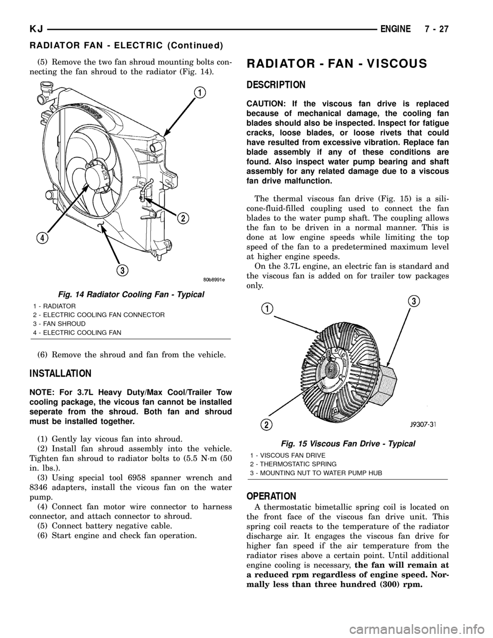
(5) Remove the two fan shroud mounting bolts con-
necting the fan shroud to the radiator (Fig. 14).
(6) Remove the shroud and fan from the vehicle.
INSTALLATION
NOTE: For 3.7L Heavy Duty/Max Cool/Trailer Tow
cooling package, the vicous fan cannot be installed
seperate from the shroud. Both fan and shroud
must be installed together.
(1) Gently lay vicous fan into shroud.
(2) Install fan shroud assembly into the vehicle.
Tighten fan shroud to radiator bolts to (5.5 N´m (50
in. lbs.).
(3) Using special tool 6958 spanner wrench and
8346 adapters, install the vicous fan on the water
pump.
(4) Connect fan motor wire connector to harness
connector, and attach connector to shroud.
(5) Connect battery negative cable.
(6) Start engine and check fan operation.
RADIATOR - FAN - VISCOUS
DESCRIPTION
CAUTION: If the viscous fan drive is replaced
because of mechanical damage, the cooling fan
blades should also be inspected. Inspect for fatigue
cracks, loose blades, or loose rivets that could
have resulted from excessive vibration. Replace fan
blade assembly if any of these conditions are
found. Also inspect water pump bearing and shaft
assembly for any related damage due to a viscous
fan drive malfunction.
The thermal viscous fan drive (Fig. 15) is a sili-
cone-fluid-filled coupling used to connect the fan
blades to the water pump shaft. The coupling allows
the fan to be driven in a normal manner. This is
done at low engine speeds while limiting the top
speed of the fan to a predetermined maximum level
at higher engine speeds.
On the 3.7L engine, an electric fan is standard and
the viscous fan is added on for trailer tow packages
only.
OPERATION
A thermostatic bimetallic spring coil is located on
the front face of the viscous fan drive unit. This
spring coil reacts to the temperature of the radiator
discharge air. It engages the viscous fan drive for
higher fan speed if the air temperature from the
radiator rises above a certain point. Until additional
engine cooling is necessary,the fan will remain at
a reduced rpm regardless of engine speed. Nor-
mally less than three hundred (300) rpm.
Fig. 14 Radiator Cooling Fan - Typical
1 - RADIATOR
2 - ELECTRIC COOLING FAN CONNECTOR
3 - FAN SHROUD
4 - ELECTRIC COOLING FAN
Fig. 15 Viscous Fan Drive - Typical
1 - VISCOUS FAN DRIVE
2 - THERMOSTATIC SPRING
3 - MOUNTING NUT TO WATER PUMP HUB
KJENGINE 7 - 27
RADIATOR FAN - ELECTRIC (Continued)
Page 248 of 1803
COOLING - 2.4L
TABLE OF CONTENTS
page page
COOLING - 2.4L
DESCRIPTION
DESCRIPTION - COOLING SYSTEM 2.4L
ENGINE..............................1
DESCRIPTION - HOSE CLAMPS...........1
OPERATION
OPERATION - COOLING SYSTEM.........2
OPERATION - HOSE CLAMPS............2
DIAGNOSIS AND TESTING
DIAGNOSIS AND TESTING - ON-BOARD
DIAGNOSTICS (OBD)...................2
DIAGNOSIS AND TESTING - PRELIMINARY
CHECKS.............................2
DIAGNOSIS AND TESTING - COOLING
SYSTEM LEAKS.......................2
DIAGNOSIS AND TESTING - COOLING
SYSTEM DIAGNOSIS CHART.............5STANDARD PROCEDURE
STANDARD PROCEDURE - DRAINING
COOLING SYSTEM....................11
STANDARD PROCEDURE - REFILLING
COOLING SYSTEM....................11
STANDARD PROCEDURE - COOLING
SYSTEM - REVERSE FLUSHING..........12
SPECIFICATIONS
TORQUE............................13
SPECIAL TOOLS
COOLING...........................13
ACCESSORY DRIVE......................14
ENGINE...............................18
TRANSMISSION.........................30
COOLING - 2.4L
DESCRIPTION
DESCRIPTION - COOLING SYSTEM 2.4L
ENGINE
The cooling system consists of the following items:
²Electric cooling fan - Standard.
²Radiator
²Hot bottle pressure cap
²Thermostat
²Coolant reserve/overflow system
²Radiator in-tank transmission oil cooler (if
equipped with an automatic transmission)
²Coolant
²Water pump
²Hoses and hose clamps
DESCRIPTION - HOSE CLAMPS
The cooling system utilizes spring type hose
clamps. If a spring type clamp replacement is neces-
sary, replace with the original Mopartequipment
spring type clamp.
WARNING: CONSTANT TENSION HOSE CLAMPS
ARE USED ON MOST COOLING SYSTEM HOSES.
WHEN REMOVING OR INSTALLING, USE ONLY
TOOLS DESIGNED FOR SERVICING THIS TYPE OF
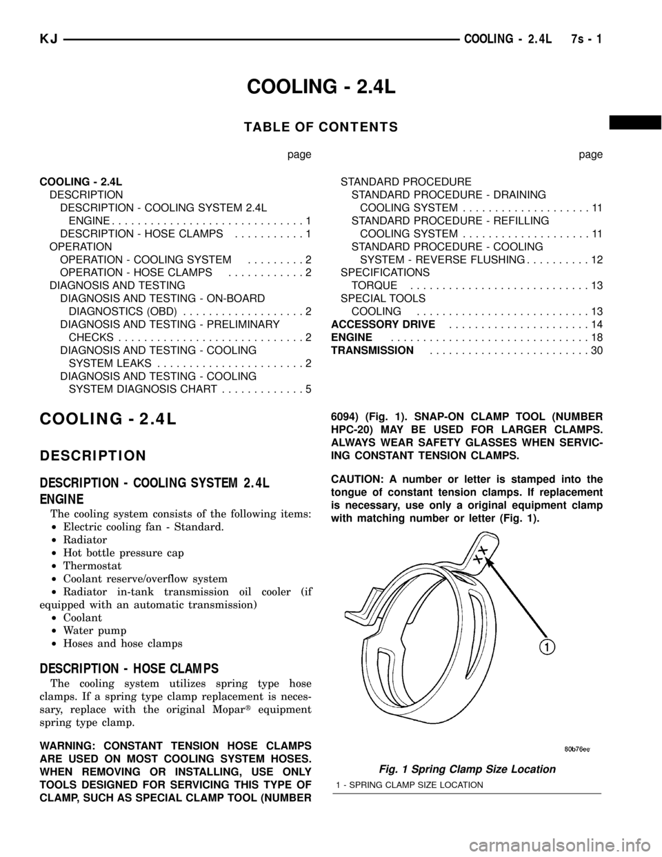
CLAMP, SUCH AS SPECIAL CLAMP TOOL (NUMBER6094) (Fig. 1). SNAP-ON CLAMP TOOL (NUMBER
HPC-20) MAY BE USED FOR LARGER CLAMPS.
ALWAYS WEAR SAFETY GLASSES WHEN SERVIC-
ING CONSTANT TENSION CLAMPS.
CAUTION: A number or letter is stamped into the
tongue of constant tension clamps. If replacement
is necessary, use only a original equipment clamp
with matching number or letter (Fig. 1).
Fig. 1 Spring Clamp Size Location
1 - SPRING CLAMP SIZE LOCATION
KJCOOLING - 2.4L 7s - 1