section 8 JEEP LIBERTY 2002 KJ / 1.G User Guide
[x] Cancel search | Manufacturer: JEEP, Model Year: 2002, Model line: LIBERTY, Model: JEEP LIBERTY 2002 KJ / 1.GPages: 1803, PDF Size: 62.3 MB
Page 221 of 1803
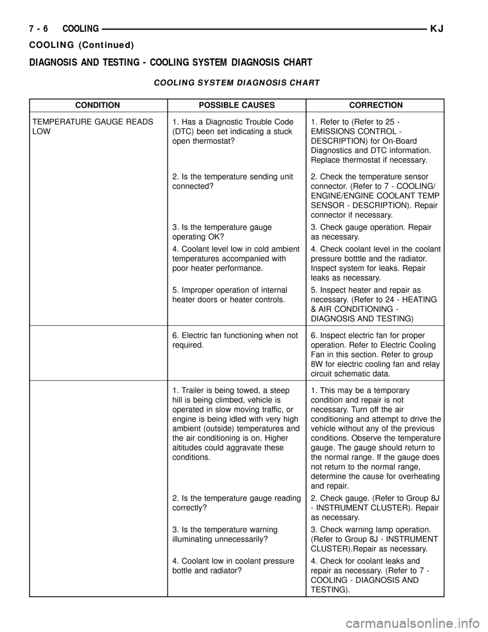
DIAGNOSIS AND TESTING - COOLING SYSTEM DIAGNOSIS CHART
COOLING SYSTEM DIAGNOSIS CHART
CONDITION POSSIBLE CAUSES CORRECTION
TEMPERATURE GAUGE READS
LOW1. Has a Diagnostic Trouble Code
(DTC) been set indicating a stuck
open thermostat?1. Refer to (Refer to 25 -
EMISSIONS CONTROL -
DESCRIPTION) for On-Board
Diagnostics and DTC information.
Replace thermostat if necessary.
2. Is the temperature sending unit
connected?2. Check the temperature sensor
connector. (Refer to 7 - COOLING/
ENGINE/ENGINE COOLANT TEMP
SENSOR - DESCRIPTION). Repair
connector if necessary.
3. Is the temperature gauge
operating OK?3. Check gauge operation. Repair
as necessary.
4. Coolant level low in cold ambient
temperatures accompanied with
poor heater performance.4. Check coolant level in the coolant
pressure botttle and the radiator.
Inspect system for leaks. Repair
leaks as necessary.
5. Improper operation of internal
heater doors or heater controls.5. Inspect heater and repair as
necessary. (Refer to 24 - HEATING
& AIR CONDITIONING -
DIAGNOSIS AND TESTING)
6. Electric fan functioning when not
required.6. Inspect electric fan for proper
operation. Refer to Electric Cooling
Fan in this section. Refer to group
8W for electric cooling fan and relay
circuit schematic data.
1. Trailer is being towed, a steep
hill is being climbed, vehicle is
operated in slow moving traffic, or
engine is being idled with very high
ambient (outside) temperatures and
the air conditioning is on. Higher
altitudes could aggravate these
conditions.1. This may be a temporary
condition and repair is not
necessary. Turn off the air
conditioning and attempt to drive the
vehicle without any of the previous
conditions. Observe the temperature
gauge. The gauge should return to
the normal range. If the gauge does
not return to the normal range,
determine the cause for overheating
and repair.
2. Is the temperature gauge reading
correctly?2. Check gauge. (Refer to Group 8J
- INSTRUMENT CLUSTER). Repair
as necessary.
3. Is the temperature warning
illuminating unnecessarily?3. Check warning lamp operation.
(Refer to Group 8J - INSTRUMENT
CLUSTER).Repair as necessary.
4. Coolant low in coolant pressure
bottle and radiator?4. Check for coolant leaks and
repair as necessary. (Refer to 7 -
COOLING - DIAGNOSIS AND
TESTING).
7 - 6 COOLINGKJ
COOLING (Continued)
Page 223 of 1803
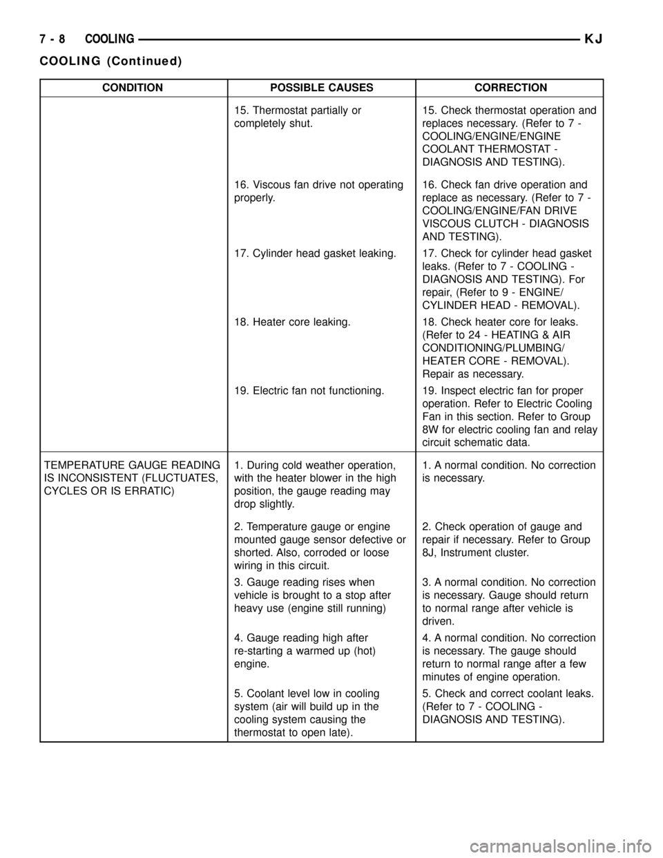
CONDITION POSSIBLE CAUSES CORRECTION
15. Thermostat partially or
completely shut.15. Check thermostat operation and
replaces necessary. (Refer to 7 -
COOLING/ENGINE/ENGINE
COOLANT THERMOSTAT -
DIAGNOSIS AND TESTING).
16. Viscous fan drive not operating
properly.16. Check fan drive operation and
replace as necessary. (Refer to 7 -
COOLING/ENGINE/FAN DRIVE
VISCOUS CLUTCH - DIAGNOSIS
AND TESTING).
17. Cylinder head gasket leaking. 17. Check for cylinder head gasket
leaks. (Refer to 7 - COOLING -
DIAGNOSIS AND TESTING). For
repair, (Refer to 9 - ENGINE/
CYLINDER HEAD - REMOVAL).
18. Heater core leaking. 18. Check heater core for leaks.
(Refer to 24 - HEATING & AIR
CONDITIONING/PLUMBING/
HEATER CORE - REMOVAL).
Repair as necessary.
19. Electric fan not functioning. 19. Inspect electric fan for proper
operation. Refer to Electric Cooling
Fan in this section. Refer to Group
8W for electric cooling fan and relay
circuit schematic data.
TEMPERATURE GAUGE READING
IS INCONSISTENT (FLUCTUATES,
CYCLES OR IS ERRATIC)1. During cold weather operation,
with the heater blower in the high
position, the gauge reading may
drop slightly.1. A normal condition. No correction
is necessary.
2. Temperature gauge or engine
mounted gauge sensor defective or
shorted. Also, corroded or loose
wiring in this circuit.2. Check operation of gauge and
repair if necessary. Refer to Group
8J, Instrument cluster.
3. Gauge reading rises when
vehicle is brought to a stop after
heavy use (engine still running)3. A normal condition. No correction
is necessary. Gauge should return
to normal range after vehicle is
driven.
4. Gauge reading high after
re-starting a warmed up (hot)
engine.4. A normal condition. No correction
is necessary. The gauge should
return to normal range after a few
minutes of engine operation.
5. Coolant level low in cooling
system (air will build up in the
cooling system causing the
thermostat to open late).5. Check and correct coolant leaks.
(Refer to 7 - COOLING -
DIAGNOSIS AND TESTING).
7 - 8 COOLINGKJ
COOLING (Continued)
Page 227 of 1803

STANDARD PROCEDURE
STANDARD PROCEDURE - DRAINING COOLING
SYSTEM 3.7L ENGINE
WARNING: DO NOT REMOVE THE CYLINDER
BLOCK DRAIN PLUGS (Fig. 5) OR LOOSEN THE
RADIATOR DRAINCOCK WITH SYSTEM HOT AND
UNDER PRESSURE. SERIOUS BURNS FROM
COOLANT CAN OCCUR.
(1) DO NOT remove radiator cap first. With engine
cold, raise vehicle on a hoist and locate radiator
draincock.
NOTE: Radiator draincock is located on the left/
lower side of radiator facing to rear of vehicle.
(2) Attach one end of a hose to the draincock. Put
the other end into a clean container. Open draincock
and drain coolant from radiator. This will empty the
coolant reserve/overflow tank. The coolant does not
have to be removed from the tank unless the system
is being refilled with a fresh mixture. When tank is
empty, remove radiator cap and continue draining
cooling system.
STANDARD PROCEDURE - REFILLING
COOLING SYSTEM 3.7L ENGINE
(1) Tighten the radiator draincock and the cylinder
block drain plug(s) (if removed).CAUTION: Failure to purge air from the cooling sys-
tem can result in an overheating condition and
severe engine damage.
(2) .Fill system using a 50/50 mixture of ethylene-
glycol antifreeze and low mineral content water.Fill
pressure bottle to service line.and install cap.
NOTE: The engine cooling system will push any
remaining air into the coolant bottle within about an
hour of normal driving. As a result, a drop in cool-
ant level in the pressure bottle may occur. If the
engine cooling system overheats and pushes cool-
ant into the overflow side of the coolant bottle, this
coolant will be sucked back into the cooling system
ONLY IF THE PRESSURE CAP IS LEFT ON THE
BOTTLE. Removing the pressure cap breaks the
vacuum path between the two bottle sections and
the coolant will not return to cooling system.
(3) With heater control unit in the HEAT position,
operate engine with pressure bottle cap in place.
(4) Add coolant to pressure bottle as necessary.
Only add coolant to the pressure bottle when
the engine is cold. Coolant level in a warm
engine will be higher due to thermal expansion.
NOTE: The coolant bottle has two chambers. Cool-
ant will normally only be in the outboard (larger) of
the two. The inboard chamber is only to recover
coolant in the event of an overheat or after a recent
service fill. The inboard chamber should normally
be empty. If there is coolant in the overflow side of
the coolant bottle (after several warm/cold cycles of
the engine) and coolant level is above cold full
when cold, disconnect the end of the overflow hose
at the fill neck and lower it into a clean container.
Allow coolant to drain into the container until emp-
tied. Reconnect overflow hose to fill neck.
STANDARD PROCEDURE - COOLING SYSTEM -
REVERSE FLUSHING
CAUTION: The cooling system normally operates at
97-to-110 kPa (14-to -16 psi) pressure. Exceeding
this pressure may damage the radiator or hoses.
Reverse flushing of the cooling system is the forc-
ing of water through the cooling system. This is done
using air pressure in the opposite direction of normal
coolant flow. It is usually only necessary with very
dirty systems with evidence of partial plugging.
CHEMICAL CLEANING
If visual inspection indicates the formation of
sludge or scaly deposits, use a radiator cleaner
Fig. 5 Drain Plug - 3.7L Engine
1 - CYLINDER BLOCK DRAIN PLUG
2 - EXHAUST MANIFOLD AND HEAT SHIELD
7 - 12 COOLINGKJ
COOLING (Continued)
Page 228 of 1803
(Mopar Radiator Kleen or equivalent) before flushing.
This will soften scale and other deposits and aid the
flushing operation.
CAUTION: Be sure instructions on the container are
followed.
REVERSE FLUSHING RADIATOR
Disconnect the radiator hoses from the radiator fit-
tings. Attach a section of radiator hose to the radia-
tor bottom outlet fitting and insert the flushing gun.
Connect a water supply hose and air supply hose to
the flushing gun.
CAUTION: The cooling system normally operates at
97-to-110 kPa (14- to-16 psi) pressure. Exceeding
this pressure may damage the radiator or hoses.
Allow the radiator to fill with water. When radiator
is filled, apply air in short blasts allowing radiator to
refill between blasts. Continue this reverse flushing
until clean water flows out through rear of radiator
cooling tube passages. For more information, refer to
operating instructions supplied with flushing equip-
ment. Have radiator cleaned more extensively by a
radiator repair shop.
REVERSE FLUSHING ENGINE
Drain the cooling system (Refer to 7 - COOLING -
STANDARD PROCEDURE). Remove the thermostat
housing and thermostat. Install the thermostat hous-
ing. Disconnect the radiator upper hose from the
radiator and attach the flushing gun to the hose. Dis-
connect the radiator lower hose from the water
pump. Attach a lead away hose to the water pump
inlet fitting.
CAUTION: Be sure that the heater control valve is
closed (heat off). This is done to prevent coolant
flow with scale and other deposits from entering
the heater core.
Connect the water supply hose and air supply hose
to the flushing gun. Allow the engine to fill with
water. When the engine is filled, apply air in short
blasts, allowing the system to fill between air blasts.
Continue until clean water flows through the lead
away hose. For more information, refer to operating
instructions supplied with flushing equipment.
Remove the lead away hose, flushing gun, water
supply hose and air supply hose. Remove the thermo-
stat housing (Refer to 7 - COOLING/ENGINE/EN-
GINE COOLANT THERMOSTAT - REMOVAL).
Install the thermostat and housing with a replace-
ment gasket (Refer to 7 - COOLING/ENGINE/EN-
GINE COOLANT THERMOSTAT -INSTALLATION). Connect the radiator hoses. Refill
the cooling system with the correct antifreeze/water
mixture (Refer to 7 - COOLING - STANDARD PRO-
CEDURE).
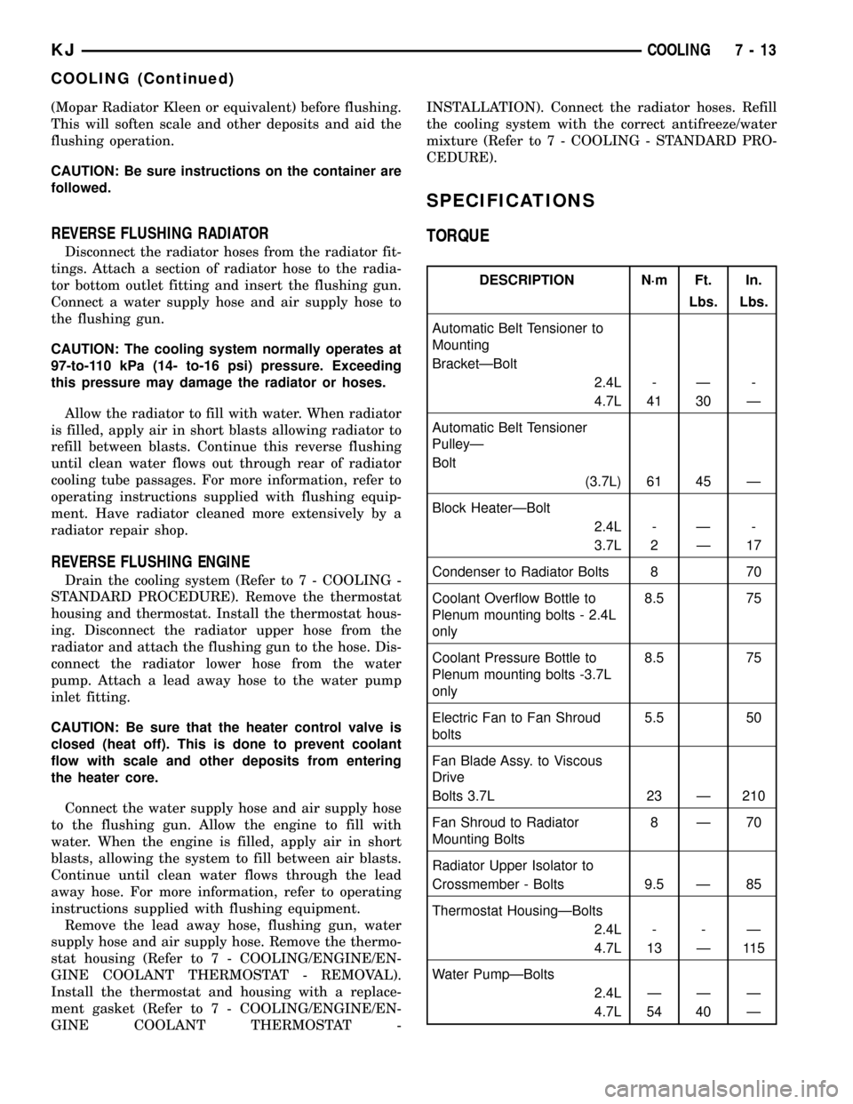
SPECIFICATIONS
TORQUE
DESCRIPTION N´m Ft. In.
Lbs. Lbs.
Automatic Belt Tensioner to
Mounting
BracketÐBolt
2.4L - Ð -
4.7L 41 30 Ð
Automatic Belt Tensioner
PulleyÐ
Bolt
(3.7L) 61 45 Ð
Block HeaterÐBolt
2.4L - Ð -
3.7L 2 Ð 17
Condenser to Radiator Bolts 8 70
Coolant Overflow Bottle to
Plenum mounting bolts - 2.4L
only8.5 75
Coolant Pressure Bottle to
Plenum mounting bolts -3.7L
only8.5 75
Electric Fan to Fan Shroud
bolts5.5 50
Fan Blade Assy. to Viscous
Drive
Bolts 3.7L 23 Ð 210
Fan Shroud to Radiator
Mounting Bolts8Ð70
Radiator Upper Isolator to
Crossmember - Bolts 9.5 Ð 85
Thermostat HousingÐBolts
2.4L - - Ð
4.7L 13 Ð 115
Water PumpÐBolts
2.4L Ð Ð Ð
4.7L 54 40 Ð
KJCOOLING 7 - 13
COOLING (Continued)
Page 249 of 1803

OPERATION
OPERATION - COOLING SYSTEM
The cooling system regulates engine operating tem-
perature. It allows the engine to reach normal oper-
ating temperature as quickly as possible. It also
maintains normal operating temperature and pre-
vents overheating.
The cooling system also provides a means of heat-
ing the passenger compartment and cooling the auto-
matic transmission fluid (if equipped). The cooling
system is pressurized and uses a centrifugal water
pump to circulate coolant throughout the system.
OPERATION - HOSE CLAMPS
The spring type hose clamp applies constant ten-
sion on a hose connection. To remove a spring type
hose clamp, only use constant tension clamp pliers
designed to compress the hose clamp.
DIAGNOSIS AND TESTING
DIAGNOSIS AND TESTING - ON-BOARD
DIAGNOSTICS (OBD)
COOLING SYSTEM RELATED DIAGNOSTICS
The powertrain control module (PCM) has been
programmed to monitor certain cooling system com-
ponents:
²If the engine has remained cool for too long a
period, such as with a stuck open thermostat, a Diag-
nostic Trouble Code (DTC) can be set.
²If an open or shorted condition has developed in
the relay circuit controlling the electric radiator fan,
a Diagnostic Trouble Code (DTC) can be set.
If the problem is sensed in a monitored circuit
often enough to indicated an actual problem, a DTC
is stored. The DTC will be stored in the PCM mem-
ory for eventual display to the service technician.
(Refer to 25 - EMISSIONS CONTROL - DESCRIP-
TION).
ACCESSING DIAGNOSTIC TROUBLE CODES
To read DTC's and to obtain cooling system data,
(Refer to 25 - EMISSIONS CONTROL - DESCRIP-
TION).
ERASING TROUBLE CODES
After the problem has been repaired, use the DRB
scan tool to erase a DTC. Refer to the appropriate
Powertrain Diagnostic Procedures service informa-
tion for operation of the DRB scan tool.
DIAGNOSIS AND TESTING - PRELIMINARY
CHECKS
ENGINE COOLING SYSTEM OVERHEATING
Establish what driving conditions caused the com-
plaint. Abnormal loads on the cooling system such as
the following may be the cause:
²PROLONGED IDLE
²VERY HIGH AMBIENT TEMPERATURE
²SLIGHT TAIL WIND AT IDLE
²SLOW TRAFFIC
²TRAFFIC JAMS
²HIGH SPEED
²STEEP GRADES
Driving techniques that avoid overheating are:
²Idle with A/C off when temperature gauge is at
end of normal range.
(1) TRAILER TOWING:
Consult Trailer Towing section of owners manual.
Do not exceed limits.
(2) RECENT SERVICE OR ACCIDENT REPAIR:
Determine if any recent service has been per-
formed on vehicle that may effect cooling system.
This may be:
²Engine adjustments (incorrect timing)
²Slipping engine accessory drive belt(s)
²Brakes (possibly dragging)
²Changed parts. Incorrect water pump, or pump
rotating in wrong direction due to belt not correctly
routed
²Reconditioned radiator or cooling system refill-
ing (possibly under filled or air trapped in system).
NOTE: If investigation reveals none of the previous
items as a cause for an engine overheating com-
plaint, refer to following Cooling System Diagnosis
charts.
These charts are to be used as a quick-reference
only. Refer to the group text for information.
DIAGNOSIS AND TESTING - COOLING SYSTEM
LEAKS
ULTRAVIOLET LIGHT METHOD
A leak detection additive is available through the
parts department that can be added to cooling sys-
tem. The additive is highly visible under ultraviolet
light (black light). Pour one ounce of additive into
cooling system. Place heater control unit in HEAT
position. Start and operate engine until radiator
upper hose is warm to touch. Aim the commercially
available black light tool at components to be
checked. If leaks are present, black light will cause
additive to glow a bright green color.
7s - 2 COOLING - 2.4LKJ
COOLING - 2.4L (Continued)
Page 252 of 1803
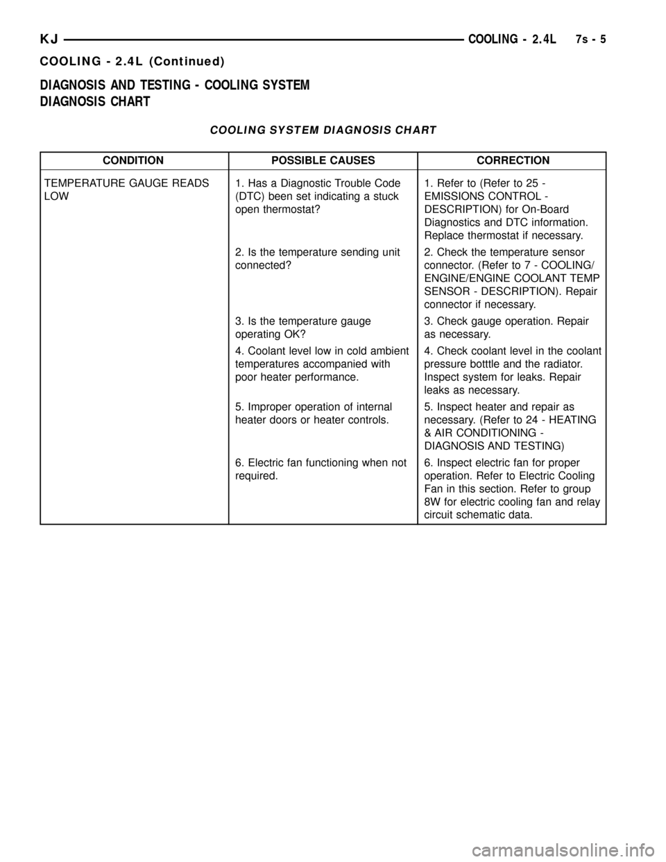
DIAGNOSIS AND TESTING - COOLING SYSTEM
DIAGNOSIS CHART
COOLING SYSTEM DIAGNOSIS CHART
CONDITION POSSIBLE CAUSES CORRECTION
TEMPERATURE GAUGE READS
LOW1. Has a Diagnostic Trouble Code
(DTC) been set indicating a stuck
open thermostat?1. Refer to (Refer to 25 -
EMISSIONS CONTROL -
DESCRIPTION) for On-Board
Diagnostics and DTC information.
Replace thermostat if necessary.
2. Is the temperature sending unit
connected?2. Check the temperature sensor
connector. (Refer to 7 - COOLING/
ENGINE/ENGINE COOLANT TEMP
SENSOR - DESCRIPTION). Repair
connector if necessary.
3. Is the temperature gauge
operating OK?3. Check gauge operation. Repair
as necessary.
4. Coolant level low in cold ambient
temperatures accompanied with
poor heater performance.4. Check coolant level in the coolant
pressure botttle and the radiator.
Inspect system for leaks. Repair
leaks as necessary.
5. Improper operation of internal
heater doors or heater controls.5. Inspect heater and repair as
necessary. (Refer to 24 - HEATING
& AIR CONDITIONING -
DIAGNOSIS AND TESTING)
6. Electric fan functioning when not
required.6. Inspect electric fan for proper
operation. Refer to Electric Cooling
Fan in this section. Refer to group
8W for electric cooling fan and relay
circuit schematic data.
KJCOOLING - 2.4L7s-5
COOLING - 2.4L (Continued)
Page 254 of 1803
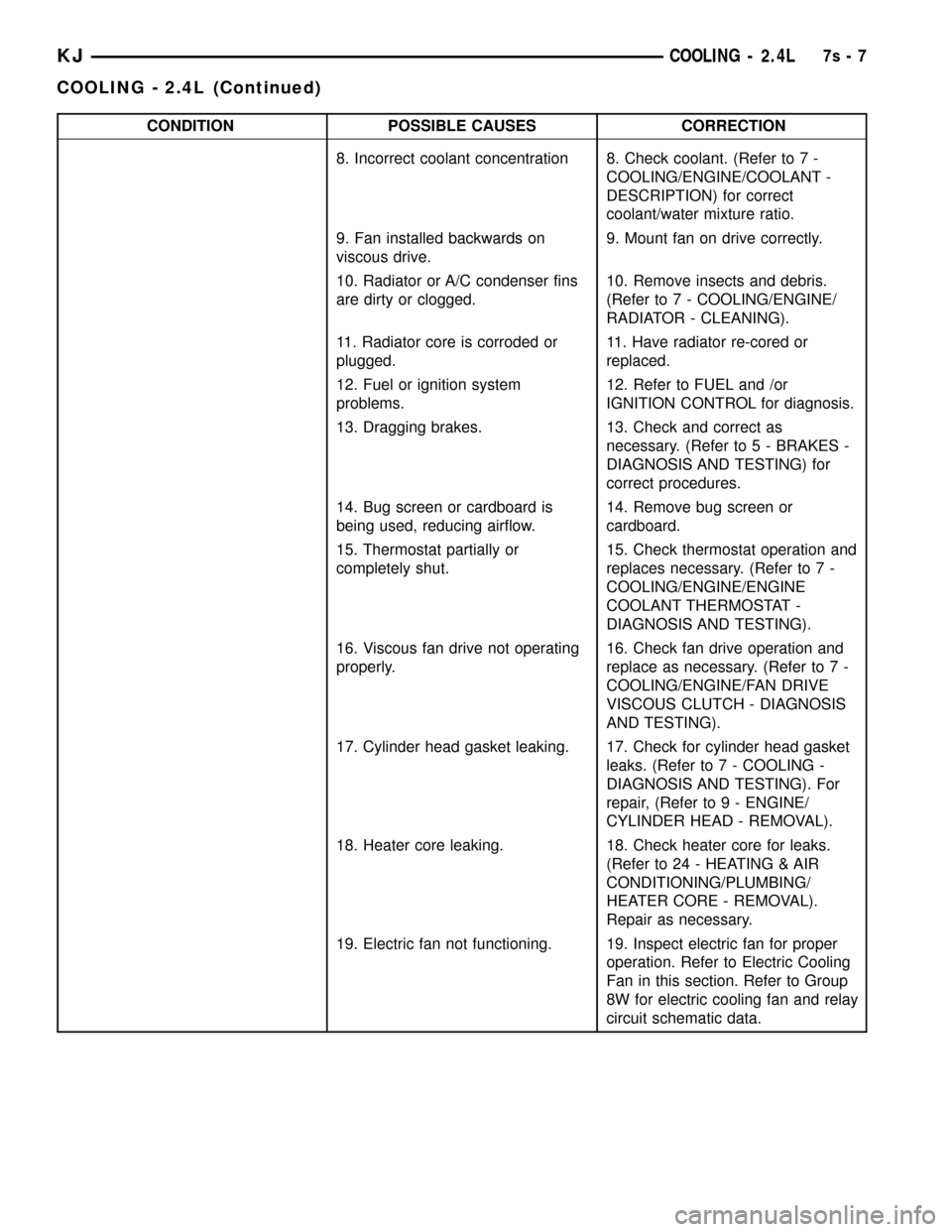
CONDITION POSSIBLE CAUSES CORRECTION
8. Incorrect coolant concentration 8. Check coolant. (Refer to 7 -
COOLING/ENGINE/COOLANT -
DESCRIPTION) for correct
coolant/water mixture ratio.
9. Fan installed backwards on
viscous drive.9. Mount fan on drive correctly.
10. Radiator or A/C condenser fins
are dirty or clogged.10. Remove insects and debris.
(Refer to 7 - COOLING/ENGINE/
RADIATOR - CLEANING).
11. Radiator core is corroded or
plugged.11. Have radiator re-cored or
replaced.
12. Fuel or ignition system
problems.12. Refer to FUEL and /or
IGNITION CONTROL for diagnosis.
13. Dragging brakes. 13. Check and correct as
necessary. (Refer to 5 - BRAKES -
DIAGNOSIS AND TESTING) for
correct procedures.
14. Bug screen or cardboard is
being used, reducing airflow.14. Remove bug screen or
cardboard.
15. Thermostat partially or
completely shut.15. Check thermostat operation and
replaces necessary. (Refer to 7 -
COOLING/ENGINE/ENGINE
COOLANT THERMOSTAT -
DIAGNOSIS AND TESTING).
16. Viscous fan drive not operating
properly.16. Check fan drive operation and
replace as necessary. (Refer to 7 -
COOLING/ENGINE/FAN DRIVE
VISCOUS CLUTCH - DIAGNOSIS
AND TESTING).
17. Cylinder head gasket leaking. 17. Check for cylinder head gasket
leaks. (Refer to 7 - COOLING -
DIAGNOSIS AND TESTING). For
repair, (Refer to 9 - ENGINE/
CYLINDER HEAD - REMOVAL).
18. Heater core leaking. 18. Check heater core for leaks.
(Refer to 24 - HEATING & AIR
CONDITIONING/PLUMBING/
HEATER CORE - REMOVAL).
Repair as necessary.
19. Electric fan not functioning. 19. Inspect electric fan for proper
operation. Refer to Electric Cooling
Fan in this section. Refer to Group
8W for electric cooling fan and relay
circuit schematic data.
KJCOOLING - 2.4L7s-7
COOLING - 2.4L (Continued)
Page 259 of 1803

NOTE: The engine cooling system will push any
remaining air into the coolant bottle within about an
hour of normal driving. As a result, a drop in cool-
ant level in the pressure bottle may occur. If the
engine cooling system overheats and pushes cool-
ant into the overflow side of the coolant bottle, this
coolant will be sucked back into the cooling system
ONLY IF THE PRESSURE CAP IS LEFT ON THE
BOTTLE. Removing the pressure cap breaks the
vacuum path between the two bottle sections and
the coolant will not return to cooling system.
(3) With heater control unit in the HEAT position,
operate engine with pressure bottle cap in place.
(4) Add coolant to pressure bottle as necessary.
Only add coolant to the pressure bottle when
the engine is cold. Coolant level in a warm
engine will be higher due to thermal expansion.
NOTE: The coolant bottle has two chambers. Cool-
ant will normally only be in the outboard (larger) of
the two. The inboard chamber is only to recover
coolant in the event of an overheat or after a recent
service fill. The inboard chamber should normally
be empty. If there is coolant in the overflow side of
the coolant bottle (after several warm/cold cycles of
the engine) and coolant level is above cold full
when cold, disconnect the end of the overflow hose
at the fill neck and lower it into a clean container.
Allow coolant to drain into the container until emp-
tied. Reconnect overflow hose to fill neck.
STANDARD PROCEDURE - COOLING SYSTEM -
REVERSE FLUSHING
CAUTION: The cooling system normally operates at
97-to-110 kPa (14-to -16 psi) pressure. Exceeding
this pressure may damage the radiator or hoses.
Reverse flushing of the cooling system is the forc-
ing of water through the cooling system. This is done
using air pressure in the opposite direction of normal
coolant flow. It is usually only necessary with very
dirty systems with evidence of partial plugging.
CHEMICAL CLEANING
If visual inspection indicates the formation of
sludge or scaly deposits, use a radiator cleaner
(Mopar Radiator Kleen or equivalent) before flushing.
This will soften scale and other deposits and aid the
flushing operation.
CAUTION: Be sure instructions on the container are
followed.
REVERSE FLUSHING RADIATOR
Disconnect the radiator hoses from the radiator fit-
tings. Attach a section of radiator hose to the radia-
tor bottom outlet fitting and insert the flushing gun.
Connect a water supply hose and air supply hose to
the flushing gun.
CAUTION: The cooling system normally operates at
97-to-110 kPa (14- to-16 psi) pressure. Exceeding
this pressure may damage the radiator or hoses.
Allow the radiator to fill with water. When radiator
is filled, apply air in short blasts allowing radiator to
refill between blasts. Continue this reverse flushing
until clean water flows out through rear of radiator
cooling tube passages. For more information, refer to
operating instructions supplied with flushing equip-
ment. Have radiator cleaned more extensively by a
radiator repair shop.
REVERSE FLUSHING ENGINE
Drain the cooling system (Refer to 7 - COOLING -
STANDARD PROCEDURE). Remove the thermostat
housing and thermostat. Install the thermostat hous-
ing. Disconnect the radiator upper hose from the
radiator and attach the flushing gun to the hose. Dis-
connect the radiator lower hose from the water
pump. Attach a lead away hose to the water pump
inlet fitting.
CAUTION: Be sure that the heater control valve is
closed (heat off). This is done to prevent coolant
flow with scale and other deposits from entering
the heater core.
Connect the water supply hose and air supply hose
to the flushing gun. Allow the engine to fill with
water. When the engine is filled, apply air in short
blasts, allowing the system to fill between air blasts.
Continue until clean water flows through the lead
away hose. For more information, refer to operating
instructions supplied with flushing equipment.
Remove the lead away hose, flushing gun, water
supply hose and air supply hose. Remove the thermo-
stat housing (Refer to 7 - COOLING/ENGINE/EN-
GINE COOLANT THERMOSTAT - REMOVAL).
Install the thermostat and housing with a replace-
ment gasket (Refer to 7 - COOLING/ENGINE/EN-
GINE COOLANT THERMOSTAT -
INSTALLATION). Connect the radiator hoses. Refill
the cooling system with the correct antifreeze/water
mixture (Refer to 7 - COOLING - STANDARD PRO-
CEDURE).
7s - 12 COOLING - 2.4LKJ
COOLING - 2.4L (Continued)
Page 321 of 1803

controls the ground for the heated seat switch indi-
cator lamps (LED's).
When a heated seat switch (Driver or Passenger) is
depressed a signal is received by the heated seat
module, the module energizes the proper indicator
LED (Low or High) in the switch by grounding the
indicator lamp circuit to indicate that the heated seat
system is operating. At the same time, the heated
seat module energizes the selected heated seat sensor
circuit and the sensor provides the module with an
input indicating the surface temperature of the
selected seat cushion.
The Low heat set point is about 36É C (96.8É F),
and the High heat set point is about 42É C (107.6É F).
If the seat cushion surface temperature input is
below the temperature set point for the selected tem-
perature setting, the heated seat module energizes
an N-channel Field Effect Transistor (N-FET) within
the module which energizes the heated seat elements
in the selected seat cushion and back. When the sen-
sor input to the module indicates the correct temper-
ature set point has been achieved, the module
de-energizes the N-FET which de-energizes the
heated seat elements. The heated seat module will
continue to cycle the N-FET as needed to maintain
the selected temperature set point.
If the heated seat module detects a heated seat
sensor value input that is out of range or a shorted
or open heated seat element circuit, it will notify the
vehicle operator or the repair technician of this con-
dition by flashing the High and/or Low indicator
lamps in the affected heated seat switch. Refer to
Diagnosis and Testing Heated Seat Systemin
Heated Systems for flashing LED diagnosis and test-
ing procedures. Refer toDiagnosis and Testing
Heated Seat Modulein this section for heated seat
module diagnosis and testing procedures. Also refer
to the Body Diagnostic Manual for additional diagno-
sis and testing procedures.
DIAGNOSIS AND TESTING - HEATED SEAT
MODULE
If a heated seat fails to heat and one or both of the
indicator lamps on a heated seat switch flash, refer
toHeated Seat System Diagnosis and Testingin
Heated Systems for flashing LED failure identifica-
tion. Refer toWiring Diagramsin for complete
heated seat system wiring diagrams.
(1) Remove the heated seat module from its
mounting location (Refer to 8 - ELECTRICAL/ELEC-
TRONIC CONTROL MODULES/MEMORY HEATED
SEAT/MIRROR MODULE - REMOVAL).NOTE: ANY RESISTANCE VALUES (OHMSV) GIVEN
IN THE FOLLOWING TEXT ARE SUPPLIED USING
THE AUTOMATIC RANGE GENERATED BY A
FLUKETAUTOMOTIVE METER. IF ANOTHER TYPE
OF MEASURING DEVICE IS USED THE VALUES
GENERATED MAY NOT BE THE SAME AS THE
RESULTS SHOWN HERE, OR MAY HAVE TO BE
CONVERTED TO THE RANGE USED HERE.
RIGHT SEAT HEATER INOPERATIVE
(1) If a heated seat heats but one or both indicator
lamps (LED's) on the heated seat switch fail to illu-
minate, check the driver circuit with the inoperative
LED for a short to ground. If OK, replace the heated
seat switch. If NOT OK repair the short to ground as
required and than replace the heated seat switch.
NOTE: IF THE RIGHT SEAT CUSHION IS ALREADY
WARM THE FOLLOWING STEP WILL NOT PROVE
CONCLUSIVE.
(2) Back-probe the heated seat module wire har-
ness connector (Fig. 15), do not disconnect. Check
cavity #3 for battery voltage when the right heated
seat switch is turned ªONº, voltage should be
present, If OK go to Step 3 If NOT OK, test the right
heated seat switch (Refer to 8 - ELECTRICAL/
HEATED SEATS/PASSENGER HEATED SEAT
SWITCH - DIAGNOSIS AND TESTING). If the
switch tests OK, check for continuity between the
switch and control module on the MUX circuit, If OK
replace the heated seat control module. If NOT OK,
repair the open or shorted MUX circuit as required.
Fig. 15 Heated Seat Module Electrical Connector
8E - 22 ELECTRONIC CONTROL MODULESKJ
HEATED SEAT MODULE (Continued)
Page 325 of 1803

²Battery Thermal Guard- The battery thermal
guard insulates the battery to protect it from engine
compartment temperature extremes.
²Battery Tray- The battery tray provides a
secure mounting location in the vehicle for the bat-
tery and an anchor point for the battery holddown
hardware.
For battery system maintenance schedules and
jump starting procedures, see the owner's manual in
the vehicle glove box. Optionally, refer to Lubrication
and Maintenance for the proper battery jump start-
ing procedures. While battery charging can be consid-
ered a maintenance procedure, the battery charging
procedures and related information are located in the
service procedures section of this service manual.
This was done because the battery must be fully-
charged before any battery system diagnosis or test-
ing procedures can be performed. Refer to Standard
Procedures for the proper battery charging proce-
dures.
OPERATION
The battery system is designed to provide a safe,
efficient, reliable and mobile means of delivering and
storing electrical energy. This electrical energy is
required to operate the engine starting system, as
well as to operate many of the other vehicle acces-
sory systems for limited durations while the engine
and/or the charging system are not operating. The
battery system is also designed to provide a reserve
of electrical energy to supplement the charging sys-
tem for short durations while the engine is running
and the electrical current demands of the vehicle
exceed the output of the charging system. In addition
to delivering, and storing electrical energy for the
vehicle, the battery system serves as a capacitor and
voltage stabilizer for the vehicle electrical system. It
absorbs most abnormal or transient voltages caused
by the switching of any of the electrical components
or circuits in the vehicle.
DIAGNOSIS AND TESTING - BATTERY SYSTEM
The battery, starting, and charging systems in the
vehicle operate with one another and must be testedas a complete system. In order for the engine to start
and the battery to maintain its charge properly, all of
the components that are used in these systems must
perform within specifications. It is important that
the battery, starting, and charging systems be thor-
oughly tested and inspected any time a battery needs
to be charged or replaced. The cause of abnormal bat-
tery discharge, overcharging or early battery failure
must be diagnosed and corrected before a battery is
replaced and before a vehicle is returned to service.
The service information for these systems has been
separated within this service manual to make it eas-
ier to locate the specific information you are seeking.
However, when attempting to diagnose any of these
systems, it is important that you keep their interde-
pendency in mind.
The diagnostic procedures used for the battery,
starting, and charging systems include the most
basic conventional diagnostic methods, to the more
sophisticated On-Board Diagnostics (OBD) built into
the Powertrain Control Module (PCM). Use of an
induction-type milliampere ammeter, a volt/ohmme-
ter, a battery charger, a carbon pile rheostat (load
tester) and a 12-volt test lamp may be required. All
OBD-sensed systems are monitored by the PCM.
Each monitored circuit is assigned a Diagnostic Trou-
ble Code (DTC). The PCM will store a DTC in elec-
tronic memory for any failure it detects. Refer to
Charging System for the proper charging system on-
board diagnostic test procedures.
MIDTRONICS ELECTRICAL SYSTEM TESTER
The Midtronicstautomotive battery and charging
system tester is designed to help the dealership tech-
nicians diagnose the cause of a defective battery or
charging system. Follow the instruction manual sup-
plied with the tester to properly diagnose a vehicle. If
the instruction manual is not available refer to the
standard procedure in this section, which includes
the directions for using the midtronics electrical sys-
tem tester.
8F - 2 BATTERY SYSTEMKJ
BATTERY SYSTEM (Continued)