Transmi JEEP LIBERTY 2002 KJ / 1.G Workshop Manual
[x] Cancel search | Manufacturer: JEEP, Model Year: 2002, Model line: LIBERTY, Model: JEEP LIBERTY 2002 KJ / 1.GPages: 1803, PDF Size: 62.3 MB
Page 1438 of 1803
SPECIFICATIONS
TORQUE CHART
TORQUE SPECIFICATIONS
DESCRIPTION N´m Ft. Lbs. In. Lbs.
Tilt Steering Column
Steering Wheel Bolt54 40 Ð
Tilt Steering Column
Mounting Bolts17 Ð 150
Tilt Steering Column
Coupler Bolt49 36 Ð
Non-Tilt Steering Column
Steering Wheel Bolt54 40 Ð
Non-Tilt Steering Column
Mounting Bolts17 Ð 150
Non-Tilt Steering Column
Coupler Bolt49 36 Ð
Ignition Switch Screws 2 Ð 17
SPECIAL TOOLS
STEERING COLUMN
IGNITION SWITCH
DESCRIPTION
The electrical ignition switch is located on the
steering column. It is used as the main on/off switch-
ing device for most electrical components. The
mechanical key lock cylinder is used to engage/disen-
gage the electrical ignition switch.
DIAGNOSIS AND TESTING - IGNITION SWITCH
ELECTRICAL DIAGNOSIS
For ignition switch electrical schematics, Refer to
the appropriate section for the component.
MECHANICAL DIAGNOSIS (KEY DIFFICULT TO
ROTATE)
Vehicles equipped with an automatic trans-
mission and a floor mounted shifter:a cable is
used to connect the interlock device in the steering
column assembly, to the transmission floor shift
lever. This interlock system is used to lock the trans-
mission shifter in the PARK position when the key
lock cylinder is rotated to the LOCKED or ACCES-
SORY position. If the ignition key is difficult to
rotate to or from the LOCK or ACCESSORY position,
it may not be the fault of the key cylinder or the
steering column components. The brake transmission
shift interlock cable may be out of adjustment. (Refer
to 21 - TRANSMISSION/TRANSAXLE/AUTOMATIC
- 30RH/GEAR SHIFT CABLE - ADJUSTMENTS).
The interlock system within the steering column is
not serviceable. If repair is necessary, the steering
column assembly must be replaced. (Refer to 19 -
STEERING/COLUMN - REMOVAL).
Vehicles equipped with a manual transmis-
sion and a floor mounted shifter:on certain mod-
els, a button is located on the steering column behind
the ignition key lock cylinder. The button must be
manually depressed to allow rotation of the ignition
key lock cylinder to the LOCK or ACCESSORY posi-
tion. If it is difficult to rotate the key to the LOCK or
ACCESSORY position, the lever mechanism may be
defective. This mechanism is not serviceable. If
repair is necessary, the steering column assembly
must be replaced.(Refer to 19 - STEERING/COL-
UMN - REMOVAL).
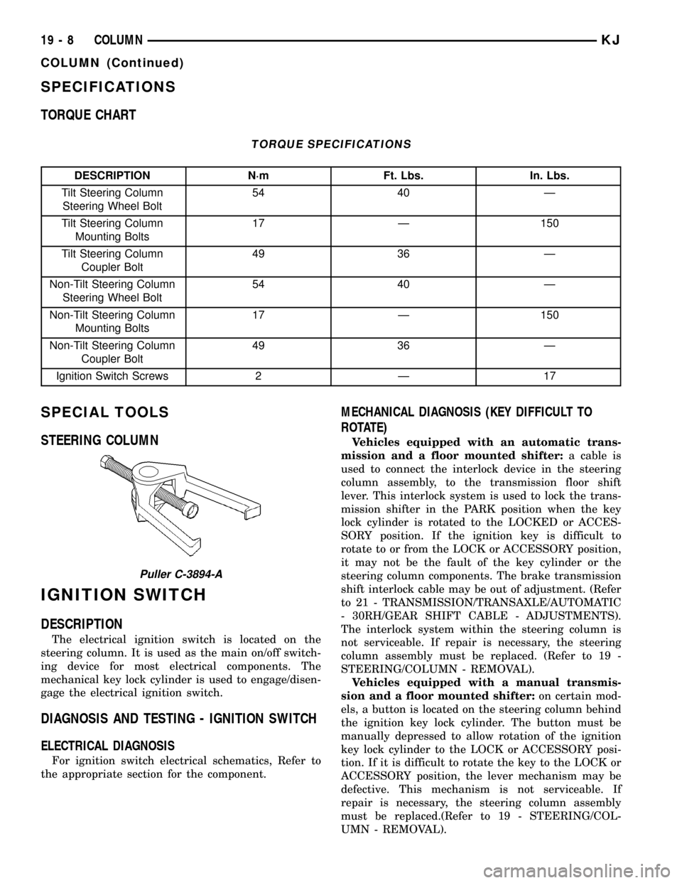
Puller C-3894-A
19 - 8 COLUMNKJ
COLUMN (Continued)
Page 1440 of 1803

KEY-IN IGNITION SWITCH
DESCRIPTION
The key-in ignition switch is integral to the igni-
tion switch, which is mounted on the left side of the
steering column, opposite the ignition lock cylinder.
It closes a path to ground for the instrument cluster
chime warning circuitry when the ignition key is
inserted in the ignition lock cylinder and the driver
door jamb switch is closed (driver door is open). The
key-in ignition switch opens the ground path when
the key is removed from the ignition lock cylinder.
The key-in ignition switch cannot be repaired and,
if faulty or damaged, the entire ignition switch must
be replaced. (Refer to 19 - STEERING/COLUMN/IG-
NITION SWITCH - REMOVAL).
DIAGNOSIS AND TESTING - KEY-IN IGNITION
SWITCH
For circuit descriptions and diagrams, Refer to the
appropriate sections on the individual components.
WARNING: ON VEHICLES EQUIPPED WITH AIR-
BAGS, REFER TO ELECTRICAL - PASSIVE
RESTRAINT SYSTEMS BEFORE ATTEMPTING ANY
STEERING WHEEL, STEERING COLUMN, OR
INSTRUMENT PANEL COMPONENT DIAGNOSIS OR
SERVICE. FAILURE TO TAKE THE PROPER PRE-
CAUTIONS COULD RESULT IN ACCIDENTAL AIR-
BAG DEPLOYMENT AND POSSIBLE PERSONAL
INJURY.
(1) Disconnect and isolate the battery negative
cable. Remove the steering column shrouds. Unplug
the key-in ignition switch wire harness connector
from the ignition switch.
(2) Check for continuity between the key-in switch
sense circuit and the left front door jamb switch
sense circuit terminals of the key-in ignition switch.
There should be continuity with the key in the igni-
tion lock cylinder, and no continuity with the key
removed from the ignition lock cylinder. If OK, go to
Step 3. If not OK, replace the faulty ignition switch
assembly.
(3) Check for continuity between the left front door
jamb switch sense circuit cavity of the key-in ignition
switch wire harness connector and a good ground.
There should be continuity with the driver door open,
and no continuity with the driver door closed. If OK,
see the diagnosis for Instrument Cluster in this
group. If not OK, repair the circuit to the driver door
jamb switch as required.
LOCK CYLINDER
REMOVAL
The ignition key must be in the key cylinder for
cylinder removal. The key cylinder must be removed
first before removing ignition switch.
(1) If equipped with an automatic transmission,
place shifter in PARK position.
(2) Remove the lower shroud cover.
(3) Remove the remote keyless entry (R.K.E.) mod-
ule.
(4) Remove the halo ring around the lock cylinder.
(5) Rotate key to ON position.
(6) A release tang is located on bottom of key cyl-
inder (Fig. 10).
(7) Position a small screwdriver or pin punch into
tang access hole on bottom of steering column (Fig.
11).
(8) Push the pin punch up while pulling key cylin-
der from steering column.
Fig. 10 LOCK CYLINDER RELEASE TANG
1 - Lock Cylinder
2 - Release Tang
19 - 10 COLUMNKJ
Page 1448 of 1803

NOTE: Power steering pumps have different pres-
sure rates and are not interchangeable with other
pumps.
STANDARD PROCEDURE - POWER STEERING
PUMP - INITIAL OPERATION
WARNING: THE FLUID LEVEL SHOULD BE
CHECKED WITH ENGINE OFF TO PREVENT INJURY
FROM MOVING COMPONENTS.
CAUTION: Use MOPAR Power Steering Fluid or
equivalent. Do not use automatic transmission fluid
and do not overfill.
Wipe filler cap clean, then check the fluid level.
The dipstick should indicateCOLDwhen the fluid is
at normal ambient temperature.
(1) Fill the pump fluid reservoir to the proper level
and let the fluid settle for at least two minutes.
(2) Raise the front wheels off the ground.
(3) Slowly turn the steering wheel right and left,
lightly contacting the wheel stops at least 20 times.
(4) Check the fluid level add if necessary.
(5) Lower the vehicle, start the engine and turn
the steering wheel slowly from lock to lock.
(6) Stop the engine and check the fluid level and
refill as required.
CAUTION: Do not run a vehicle with foamy fluid for
an extended period. This may cause pump damage.
(7) If the fluid is extremely foamy or milky look-
ing, allow the vehicle to stand a few minutes and
repeat the procedure.
(8) Add fluid if necessary. Repeat the above proce-
dure until the fluid level remains constant after run-
ning the engine.
REMOVAL
REMOVAL - 3.7L
(1) Siphon out as much power steering fluid as
possible.
(2) Remove the radiator cross member (Refer to 23
- BODY/EXTERIOR/RADIATOR CROSSMEMBER -
REMOVAL).
(3) Remove the engine cooling fan (Refer to 7 -
COOLING/ENGINE/RADIATOR FAN - REMOVAL).
(4) Remove the fan shroud
(5) Remove the serpentine drive belt (Refer to 7 -
COOLING/ACCESSORY DRIVE/DRIVE BELTS -
REMOVAL).
(6) Remove the power steering high pressure hose
at the pump.
(7) Remove the return hose at the pump.
(8) Remove the three bolts securing the pump to
the bracket thru the holes in the pulley. (Fig. 3)
(9) Remove the pump from the vehicle.
REMOVAL - 2.4L
CAUTION: On vehicles equipped with the 2.4L, Do
not reuse the old power steering pump pulley it is
not intended for reuse. A new pulley must be
installed if removed.
(1) Siphon out as much power steering fluid as
possible.
(2) Remove the serpentine drive belt.
(3) Remove the power steering high pressure hose
at the pump using care not to remove the flow con-
trol valve.
(4) Remove the return hose at the pump.
Fig. 2 FLUID RESERVOIR - 2.4L
Fig. 3 POWER STEERING PUMP - 3.7L
1 - MOUNTING BOLTS
2 - RESERVOIR
3 - STEEL PULLEY
19 - 18 PUMPKJ
PUMP (Continued)
Page 1621 of 1803

INTERIOR
TABLE OF CONTENTS
page page
4WD FLOOR SHIFT BOOT
REMOVAL............................156
INSTALLATION........................156
A-PILLAR TRIM AND GRAB HANDLE
REMOVAL............................156
INSTALLATION........................156
COWL TRIM COVER
REMOVAL............................157
INSTALLATION........................157
DOOR SILL SCUFF PLATE
REMOVAL............................157
INSTALLATION........................157
ASSIST HANDLE
REMOVAL............................157
INSTALLATION........................157
B-PILLAR LOWER TRIM
REMOVAL............................157
INSTALLATION........................157
B-PILLAR UPPER TRIM
REMOVAL............................157
INSTALLATION........................158
CARPETS AND FLOOR MATS
REMOVAL............................158
INSTALLATION........................158
SHIFT BEZEL
REMOVAL............................158
INSTALLATION........................158FLOOR CONSOLE
REMOVAL............................158
INSTALLATION........................158
FLOOR CONSOLE LID LATCH
REMOVAL............................158
INSTALLATION........................158
HEADLINER
REMOVAL............................159
INSTALLATION........................159
QUARTER TRIM PANEL
REMOVAL............................159
INSTALLATION........................159
REAR DOOR SCUFF PLATE
REMOVAL............................160
INSTALLATION........................160
SUN VISOR
REMOVAL............................160
INSTALLATION........................160
SUN VISOR SUPPORT
REMOVAL............................160
INSTALLATION........................160
REAR VIEW MIRROR
REMOVAL............................161
INSTALLATION
INSTALLATION......................161
INSTALLATION - REARVIEW MIRROR
SUPPORT BRACKET..................161
4WD FLOOR SHIFT BOOT
REMOVAL
(1) Remove the shift lever and remove the boot
from the lever. (Refer to 21 - TRANSMISSION/
TRANSAXLE/TRANSFER CASE/SHIFT LEVER -
REMOVAL)
INSTALLATION
(1) Install the shift boot onto the shift lever and
install the lever. (Refer to 21 - TRANSMISSION/
TRANSAXLE/TRANSFER CASE/SHIFT LEVER -
INSTALLATION)
A-PILLAR TRIM AND GRAB
HANDLE
REMOVAL
(1) Using a small pry tool or equivalent, remove
the grab handle trim plugs.
(2) Remove the two grab handle screws.
(3) Remove the grab handle and a-pillar trim from
the a-pillar.
INSTALLATION
(1) Snap a-pillar trim and grab handle into the
a-pillar.
(2) Install the two screws and install the grab han-
dle trim plugs.
23 - 156 INTERIORKJ
Page 1683 of 1803

The blower motor is located on the passenger side
of the vehicle under the dash
(1) Disconnect and isolate the battery negative
cable.
(2) Unplug the blower motor wire harness connec-
tor (Fig. 2).
(3) Release the locking tab that secures the blower
motor and wheel assembly to the HVAC housing.
(4) Rotate and tilt the blower motor unit as needed
for clearance to remove the blower motor and wheel
from the HVAC housing.
INSTALLATION
(1) Align and install the blower motor and wheel
assembly into the HVAC housing.
(2) Rotate the blower assembly until the locking
tab secures the blower motor and wheel assembly to
the HVAC housing.
(3) Plug in the blower motor wire harness connec-
tor.
(4) Connect the battery negative cable.
FLOOR CONSOLE DUCT
REMOVAL
(1) Disconnect and isolate the battery negative
cable.
(2) Remove the floor console from the sled (Fig. 3).
Refer to Floor Console for the procedures(Refer to 23
- BODY/INTERIOR/FLOOR CONSOLE - REMOV-
AL).
(3) Lift the rear of the console duct out of the con-
sole rear mounting bracket on the sled and slide the
duct rearward to disengage it from the floor duct and
adapter.
(4) Remove the console rear duct from the vehicle.
INSTALLATION
(1) Push the console duct forward in place on the
HVAC floor duct.
(2) Align the rear tab of the console duct with the
hole on the sled bracket.
(3) Insert the push pin in the hole on the sled.
(4) Install the floor console on the floor panel
transmission tunnel(Refer to 23 - BODY/INTERIOR/
FLOOR CONSOLE - INSTALLATION).
(5) Connect the battery negative cable.
Fig. 2 HVAC BLOWER MOTOR
1 - HVAC HOUSING
2 - BLOWER MOTOR
3 - RETAINER-LOCKING TAB
4 - BLOWER MOTOR ELECTRICAL CONNECTOR
Fig. 3 CONSOLE DUCT REMOVE/INSTALL
1 - REAR DUCT ASSEMBLY
2 - REAR DUCT RETAINER SCREW
3 - REAR DUCT MOUNTING FLANGE
4 - TRANSMISSION SHIFT LEVER ASSEMBLY
5 - FRONT TO REAR DUCT CONNECTING POINT
KJDISTRIBUTION 24 - 31
BLOWER MOTOR (Continued)
Page 1694 of 1803

used to charge the refrigerant system with R-134a
refrigerant. Refer to the operating instructions sup-
plied by the equipment manufacturer for proper care
and use of this equipment.
SPECIFICATIONS - CHARGE CAPACITY
The R-134a refrigerant system charge capacity for
this vehicle is 0.737 kilograms (1.63 pounds).
A/C COMPRESSOR
DESCRIPTION
DESCRIPTION
The air conditioning system uses a Sanden
PXF-18, reciprocating swash plate-type compressor
on all models. This compressor has a fixed displace-
ment of 180 cubic centimeters (10.984 cubic inches),
and has both the suction and discharge ports located
on the cylinder head. A label identifying the use of
R-134a refrigerant is located on the compressor.
DESCRIPTION - HIGH PRESSURE RELIEF
VALVE
A high pressure relief valve is located on the com-
pressor cylinder head, which is on the rear of the
compressor. This mechanical valve is designed to
vent refrigerant from the system to protect against
damage to the compressor and other system compo-
nents, caused by condenser air flow restriction or an
overcharge of refrigerant.
OPERATION
OPERATION
The compressor is driven by the engine through an
electric clutch, drive rotor and belt arrangement. The
compressor is lubricated by refrigerant oil that is cir-
culated throughout the refrigerant system with the
refrigerant.
The compressor draws in low-pressure refrigerant
vapor from the evaporator through its suction port. It
then compresses the refrigerant into a high-pressure,
high-temperature refrigerant vapor, which is then
pumped to the condenser through the compressor dis-
charge port.
The compressor cannot be repaired. If faulty or
damaged, the entire compressor assembly must be
replaced. The compressor clutch, pulley and clutch
coil are available for service.
OPERATION - HIGH PRESSURE RELIEF VALVE
The high pressure relief valve vents the system
when a discharge pressure of 3445 to 4135 kPa (500
to 600 psi) or above is reached. The valve closes
when a minimum discharge pressure of 2756 kPa
(400 psi) is reached.
The high pressure relief valve vents only enough
refrigerant to reduce the system pressure, and then
re-seats itself. The majority of the refrigerant is con-
served in the system. If the valve vents refrigerant, it
does not mean that the valve is faulty.
The high pressure relief valve is a factory-cali-
brated unit. The valve cannot be adjusted or
repaired, and must not be removed or otherwise dis-
turbed. The valve is only serviced as a part of the
compressor assembly.
DIAGNOSIS AND TESTING - A/C COMPRESSOR
NOISE
When investigating an air conditioning related
noise, you must first know the conditions under
which the noise occurs. These conditions include:
weather, vehicle speed, transmission in gear or neu-
tral, engine speed, engine temperature, and any
other special conditions. Noises that develop during
air conditioning operation can often be misleading.
For example: What sounds like a failed front bearing
or connecting rod, may be caused by loose bolts, nuts,
mounting brackets, or a loose compressor clutch
assembly.
Drive belts are speed sensitive. At different engine
speeds and depending upon belt tension, belts can
develop noises that are mistaken for a compressor
noise. Improper belt tension can cause a misleading
noise when the compressor clutch is engaged, which
may not occur when the compressor clutch is disen-
gaged. Check the serpentine drive belt condition and
tension as described in Cooling before beginning this
procedure.
(1) Select a quiet area for testing. Duplicate the
complaint conditions as much as possible. Switch the
compressor on and off several times to clearly iden-
tify the compressor noise. Listen to the compressor
while the clutch is engaged and disengaged. Probe
the compressor with an engine stethoscope or a long
screwdriver with the handle held to your ear to bet-
ter localize the source of the noise.
(2) Loosen all of the compressor mounting hard-
ware and retighten. Tighten the compressor clutch
mounting nut. Be certain that the clutch coil is
mounted securely to the compressor, and that the
clutch plate and rotor are properly aligned and have
the correct air gap. (Refer to 24 - HEATING & AIR
CONDITIONING/CONTROLS/A/C COMPRESSOR
CLUTCH - INSTALLATION)
24 - 42 PLUMBINGKJ
PLUMBING (Continued)
Page 1715 of 1803
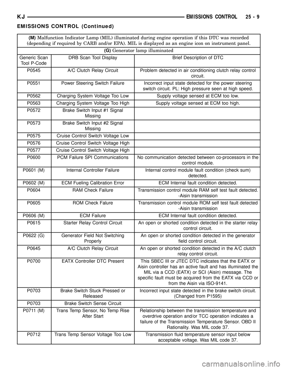
(M)Malfunction Indicator Lamp (MIL) illuminated during engine operation if this DTC was recorded
(depending if required by CARB and/or EPA). MIL is displayed as an engine icon on instrument panel.
(G)Generator lamp illuminated
Generic Scan
Tool P-CodeDRB Scan Tool Display Brief Description of DTC
P0545 A/C Clutch Relay Circuit Problem detected in air conditioning clutch relay control
circuit.
P0551 Power Steering Switch Failure Incorrect input state detected for the power steering
switch circuit. PL: High pressure seen at high speed.
P0562 Charging System Voltage Too Low Supply voltage sensed at ECM too low.
P0563 Charging System Voltage Too High Supply voltage sensed at ECM too high.
P0572 Brake Switch Input #1 Signal
Missing
P0573 Brake Switch Input #2 Signal
Missing
P0575 Cruise Control Switch Voltage Low
P0576 Cruise Control Switch Voltage High
P0577 Cruise Control Switch Voltage High
P0600 PCM Failure SPI Communications No communication detected between co-processors in the
control module.
P0601 (M) Internal Controller Failure Internal control module fault condition (check sum)
detected.
P0602 (M) ECM Fueling Calibration Error ECM Internal fault condition detected.
P0604 RAM Check Failure Transmission control module RAM self test fault detected.
-Aisin transmission
P0605 ROM Check Falure Transmission control module ROM self test fault detected
-Aisin transmission
P0606 (M) ECM Failure ECM Internal fault condition detected.
P0615 Starter Relay Control Circuit An open or shorted condition detected in the starter relay
control circuit.
P0622 (G) Generator Field Not Switching
ProperlyAn open or shorted condition detected in the generator
field control circuit.
P0645 A/C Clutch Relay Circuit An open or shorted condition detected in the A/C clutch
relay control circuit.
P0700 EATX Controller DTC Present This SBEC III or JTEC DTC indicates that the EATX or
Aisin controller has an active fault and has illuminated the
MIL via a CCD (EATX) or SCI (Aisin) message. The
specific fault must be acquired from the EATX via CCD or
from the Aisin via ISO-9141.
P0703 Brake Switch Stuck Pressed or
ReleasedIncorrect input state detected in the brake switch circuit.
(Changed from P1595)
P0703 Brake Switch Sense Circuit
P0711 (M) Trans Temp Sensor, No Temp Rise
After StartRelationship between the transmission temperature and
overdrive operation and/or TCC operation indicates a
failure of the Transmission Temperature Sensor. OBD II
Rationality. Was MIL code 37.
P0712 Trans Temp Sensor Voltage Too Low Transmission fluid temperature sensor input below
acceptable voltage. Was MIL code 37.
KJEMISSIONS CONTROL 25 - 9
EMISSIONS CONTROL (Continued)
Page 1716 of 1803
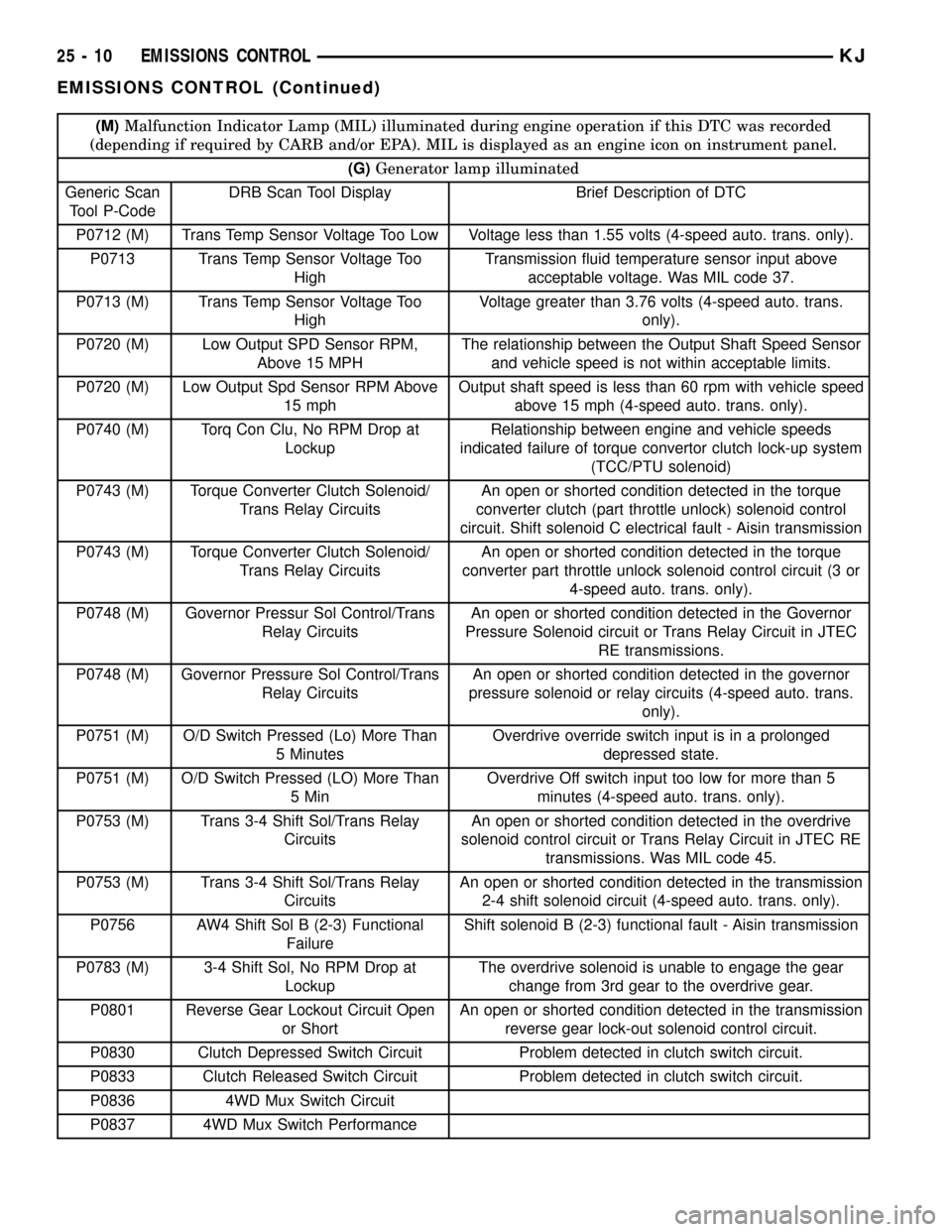
(M)Malfunction Indicator Lamp (MIL) illuminated during engine operation if this DTC was recorded
(depending if required by CARB and/or EPA). MIL is displayed as an engine icon on instrument panel.
(G)Generator lamp illuminated
Generic Scan
Tool P-CodeDRB Scan Tool Display Brief Description of DTC
P0712 (M) Trans Temp Sensor Voltage Too Low Voltage less than 1.55 volts (4-speed auto. trans. only).
P0713 Trans Temp Sensor Voltage Too
HighTransmission fluid temperature sensor input above
acceptable voltage. Was MIL code 37.
P0713 (M) Trans Temp Sensor Voltage Too
HighVoltage greater than 3.76 volts (4-speed auto. trans.
only).
P0720 (M) Low Output SPD Sensor RPM,
Above 15 MPHThe relationship between the Output Shaft Speed Sensor
and vehicle speed is not within acceptable limits.
P0720 (M) Low Output Spd Sensor RPM Above
15 mphOutput shaft speed is less than 60 rpm with vehicle speed
above 15 mph (4-speed auto. trans. only).
P0740 (M) Torq Con Clu, No RPM Drop at
LockupRelationship between engine and vehicle speeds
indicated failure of torque convertor clutch lock-up system
(TCC/PTU solenoid)
P0743 (M) Torque Converter Clutch Solenoid/
Trans Relay CircuitsAn open or shorted condition detected in the torque
converter clutch (part throttle unlock) solenoid control
circuit. Shift solenoid C electrical fault - Aisin transmission
P0743 (M) Torque Converter Clutch Solenoid/
Trans Relay CircuitsAn open or shorted condition detected in the torque
converter part throttle unlock solenoid control circuit (3 or
4-speed auto. trans. only).
P0748 (M) Governor Pressur Sol Control/Trans
Relay CircuitsAn open or shorted condition detected in the Governor
Pressure Solenoid circuit or Trans Relay Circuit in JTEC
RE transmissions.
P0748 (M) Governor Pressure Sol Control/Trans
Relay CircuitsAn open or shorted condition detected in the governor
pressure solenoid or relay circuits (4-speed auto. trans.
only).
P0751 (M) O/D Switch Pressed (Lo) More Than
5 MinutesOverdrive override switch input is in a prolonged
depressed state.
P0751 (M) O/D Switch Pressed (LO) More Than
5 MinOverdrive Off switch input too low for more than 5
minutes (4-speed auto. trans. only).
P0753 (M) Trans 3-4 Shift Sol/Trans Relay
CircuitsAn open or shorted condition detected in the overdrive
solenoid control circuit or Trans Relay Circuit in JTEC RE
transmissions. Was MIL code 45.
P0753 (M) Trans 3-4 Shift Sol/Trans Relay
CircuitsAn open or shorted condition detected in the transmission
2-4 shift solenoid circuit (4-speed auto. trans. only).
P0756 AW4 Shift Sol B (2-3) Functional
FailureShift solenoid B (2-3) functional fault - Aisin transmission
P0783 (M) 3-4 Shift Sol, No RPM Drop at
LockupThe overdrive solenoid is unable to engage the gear
change from 3rd gear to the overdrive gear.
P0801 Reverse Gear Lockout Circuit Open
or ShortAn open or shorted condition detected in the transmission
reverse gear lock-out solenoid control circuit.
P0830 Clutch Depressed Switch Circuit Problem detected in clutch switch circuit.
P0833 Clutch Released Switch Circuit Problem detected in clutch switch circuit.
P0836 4WD Mux Switch Circuit
P0837 4WD Mux Switch Performance
25 - 10 EMISSIONS CONTROLKJ
EMISSIONS CONTROL (Continued)
Page 1719 of 1803
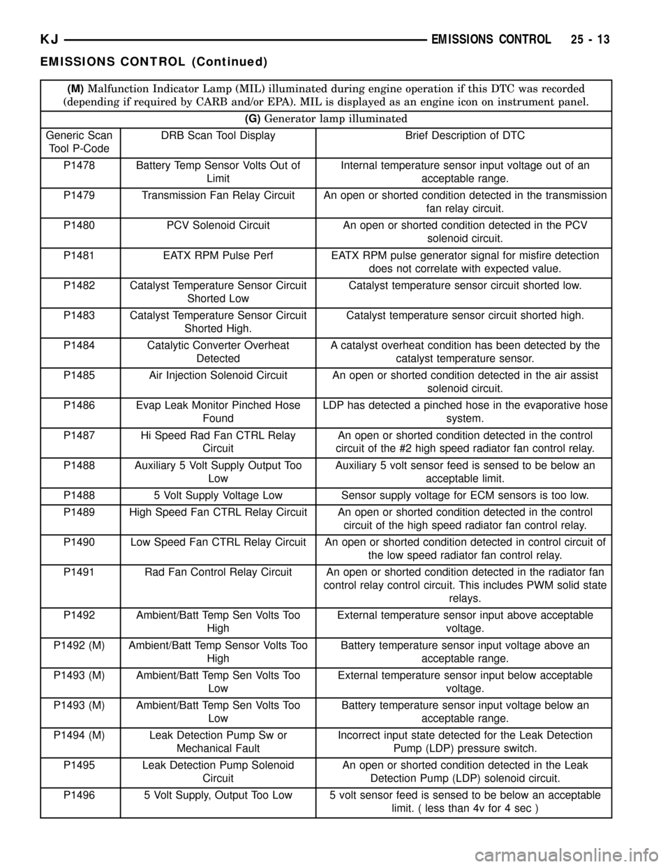
(M)Malfunction Indicator Lamp (MIL) illuminated during engine operation if this DTC was recorded
(depending if required by CARB and/or EPA). MIL is displayed as an engine icon on instrument panel.
(G)Generator lamp illuminated
Generic Scan
Tool P-CodeDRB Scan Tool Display Brief Description of DTC
P1478 Battery Temp Sensor Volts Out of
LimitInternal temperature sensor input voltage out of an
acceptable range.
P1479 Transmission Fan Relay Circuit An open or shorted condition detected in the transmission
fan relay circuit.
P1480 PCV Solenoid Circuit An open or shorted condition detected in the PCV
solenoid circuit.
P1481 EATX RPM Pulse Perf EATX RPM pulse generator signal for misfire detection
does not correlate with expected value.
P1482 Catalyst Temperature Sensor Circuit
Shorted LowCatalyst temperature sensor circuit shorted low.
P1483 Catalyst Temperature Sensor Circuit
Shorted High.Catalyst temperature sensor circuit shorted high.
P1484 Catalytic Converter Overheat
DetectedA catalyst overheat condition has been detected by the
catalyst temperature sensor.
P1485 Air Injection Solenoid Circuit An open or shorted condition detected in the air assist
solenoid circuit.
P1486 Evap Leak Monitor Pinched Hose
FoundLDP has detected a pinched hose in the evaporative hose
system.
P1487 Hi Speed Rad Fan CTRL Relay
CircuitAn open or shorted condition detected in the control
circuit of the #2 high speed radiator fan control relay.
P1488 Auxiliary 5 Volt Supply Output Too
LowAuxiliary 5 volt sensor feed is sensed to be below an
acceptable limit.
P1488 5 Volt Supply Voltage Low Sensor supply voltage for ECM sensors is too low.
P1489 High Speed Fan CTRL Relay Circuit An open or shorted condition detected in the control
circuit of the high speed radiator fan control relay.
P1490 Low Speed Fan CTRL Relay Circuit An open or shorted condition detected in control circuit of
the low speed radiator fan control relay.
P1491 Rad Fan Control Relay Circuit An open or shorted condition detected in the radiator fan
control relay control circuit. This includes PWM solid state
relays.
P1492 Ambient/Batt Temp Sen Volts Too
HighExternal temperature sensor input above acceptable
voltage.
P1492 (M) Ambient/Batt Temp Sensor Volts Too
HighBattery temperature sensor input voltage above an
acceptable range.
P1493 (M) Ambient/Batt Temp Sen Volts Too
LowExternal temperature sensor input below acceptable
voltage.
P1493 (M) Ambient/Batt Temp Sen Volts Too
LowBattery temperature sensor input voltage below an
acceptable range.
P1494 (M) Leak Detection Pump Sw or
Mechanical FaultIncorrect input state detected for the Leak Detection
Pump (LDP) pressure switch.
P1495 Leak Detection Pump Solenoid
CircuitAn open or shorted condition detected in the Leak
Detection Pump (LDP) solenoid circuit.
P1496 5 Volt Supply, Output Too Low 5 volt sensor feed is sensed to be below an acceptable
limit. ( less than 4v for 4 sec )
KJEMISSIONS CONTROL 25 - 13
EMISSIONS CONTROL (Continued)
Page 1721 of 1803
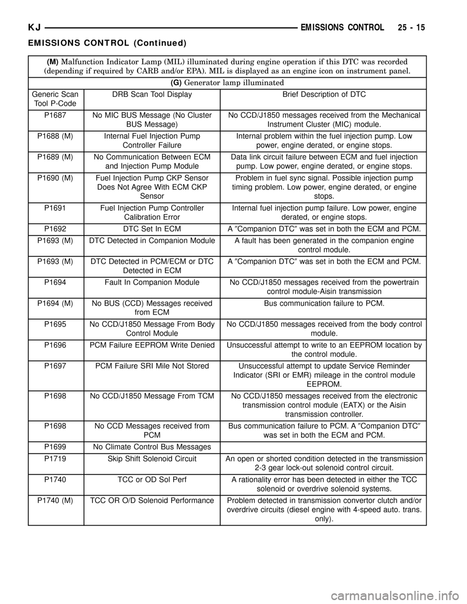
(M)Malfunction Indicator Lamp (MIL) illuminated during engine operation if this DTC was recorded
(depending if required by CARB and/or EPA). MIL is displayed as an engine icon on instrument panel.
(G)Generator lamp illuminated
Generic Scan
Tool P-CodeDRB Scan Tool Display Brief Description of DTC
P1687 No MIC BUS Message (No Cluster
BUS Message)No CCD/J1850 messages received from the Mechanical
Instrument Cluster (MIC) module.
P1688 (M) Internal Fuel Injection Pump
Controller FailureInternal problem within the fuel injection pump. Low
power, engine derated, or engine stops.
P1689 (M) No Communication Between ECM
and Injection Pump ModuleData link circuit failure between ECM and fuel injection
pump. Low power, engine derated, or engine stops.
P1690 (M) Fuel Injection Pump CKP Sensor
Does Not Agree With ECM CKP
SensorProblem in fuel sync signal. Possible injection pump
timing problem. Low power, engine derated, or engine
stops.
P1691 Fuel Injection Pump Controller
Calibration ErrorInternal fuel injection pump failure. Low power, engine
derated, or engine stops.
P1692 DTC Set In ECM A9Companion DTC9was set in both the ECM and PCM.
P1693 (M) DTC Detected in Companion Module A fault has been generated in the companion engine
control module.
P1693 (M) DTC Detected in PCM/ECM or DTC
Detected in ECMA9Companion DTC9was set in both the ECM and PCM.
P1694 Fault In Companion Module No CCD/J1850 messages received from the powertrain
control module-Aisin transmission
P1694 (M) No BUS (CCD) Messages received
from ECMBus communication failure to PCM.
P1695 No CCD/J1850 Message From Body
Control ModuleNo CCD/J1850 messages received from the body control
module.
P1696 PCM Failure EEPROM Write Denied Unsuccessful attempt to write to an EEPROM location by
the control module.
P1697 PCM Failure SRI Mile Not Stored Unsuccessful attempt to update Service Reminder
Indicator (SRI or EMR) mileage in the control module
EEPROM.
P1698 No CCD/J1850 Message From TCM No CCD/J1850 messages received from the electronic
transmission control module (EATX) or the Aisin
transmission controller.
P1698 No CCD Messages received from
PCMBus communication failure to PCM. A9Companion DTC9
was set in both the ECM and PCM.
P1699 No Climate Control Bus Messages
P1719 Skip Shift Solenoid Circuit An open or shorted condition detected in the transmission
2-3 gear lock-out solenoid control circuit.
P1740 TCC or OD Sol Perf A rationality error has been detected in either the TCC
solenoid or overdrive solenoid systems.
P1740 (M) TCC OR O/D Solenoid Performance Problem detected in transmission convertor clutch and/or
overdrive circuits (diesel engine with 4-speed auto. trans.
only).
KJEMISSIONS CONTROL 25 - 15
EMISSIONS CONTROL (Continued)