front fender JEEP LIBERTY 2002 KJ / 1.G Owner's Manual
[x] Cancel search | Manufacturer: JEEP, Model Year: 2002, Model line: LIBERTY, Model: JEEP LIBERTY 2002 KJ / 1.GPages: 1803, PDF Size: 62.3 MB
Page 711 of 1803
FRONT WASHER HOSES/
TUBES
DESCRIPTION
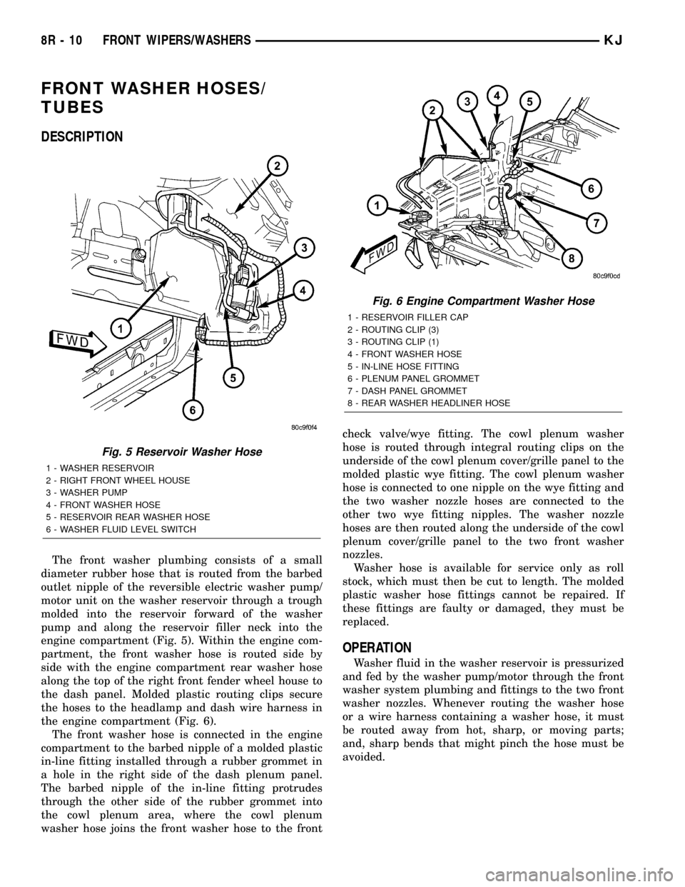
The front washer plumbing consists of a small
diameter rubber hose that is routed from the barbed
outlet nipple of the reversible electric washer pump/
motor unit on the washer reservoir through a trough
molded into the reservoir forward of the washer
pump and along the reservoir filler neck into the
engine compartment (Fig. 5). Within the engine com-
partment, the front washer hose is routed side by
side with the engine compartment rear washer hose
along the top of the right front fender wheel house to
the dash panel. Molded plastic routing clips secure
the hoses to the headlamp and dash wire harness in
the engine compartment (Fig. 6).
The front washer hose is connected in the engine
compartment to the barbed nipple of a molded plastic
in-line fitting installed through a rubber grommet in
a hole in the right side of the dash plenum panel.
The barbed nipple of the in-line fitting protrudes
through the other side of the rubber grommet into
the cowl plenum area, where the cowl plenum
washer hose joins the front washer hose to the frontcheck valve/wye fitting. The cowl plenum washer
hose is routed through integral routing clips on the
underside of the cowl plenum cover/grille panel to the
molded plastic wye fitting. The cowl plenum washer
hose is connected to one nipple on the wye fitting and
the two washer nozzle hoses are connected to the
other two wye fitting nipples. The washer nozzle
hoses are then routed along the underside of the cowl
plenum cover/grille panel to the two front washer
nozzles.
Washer hose is available for service only as roll
stock, which must then be cut to length. The molded
plastic washer hose fittings cannot be repaired. If
these fittings are faulty or damaged, they must be
replaced.
OPERATION
Washer fluid in the washer reservoir is pressurized
and fed by the washer pump/motor through the front
washer system plumbing and fittings to the two front
washer nozzles. Whenever routing the washer hose
or a wire harness containing a washer hose, it must
be routed away from hot, sharp, or moving parts;
and, sharp bends that might pinch the hose must be
avoided.
Fig. 5 Reservoir Washer Hose
1 - WASHER RESERVOIR
2 - RIGHT FRONT WHEEL HOUSE
3 - WASHER PUMP
4 - FRONT WASHER HOSE
5 - RESERVOIR REAR WASHER HOSE
6 - WASHER FLUID LEVEL SWITCH
Fig. 6 Engine Compartment Washer Hose
1 - RESERVOIR FILLER CAP
2 - ROUTING CLIP (3)
3 - ROUTING CLIP (1)
4 - FRONT WASHER HOSE
5 - IN-LINE HOSE FITTING
6 - PLENUM PANEL GROMMET
7 - DASH PANEL GROMMET
8 - REAR WASHER HEADLINER HOSE
8R - 10 FRONT WIPERS/WASHERSKJ
Page 718 of 1803
WASHER FLUID LEVEL
SWITCH
DESCRIPTION
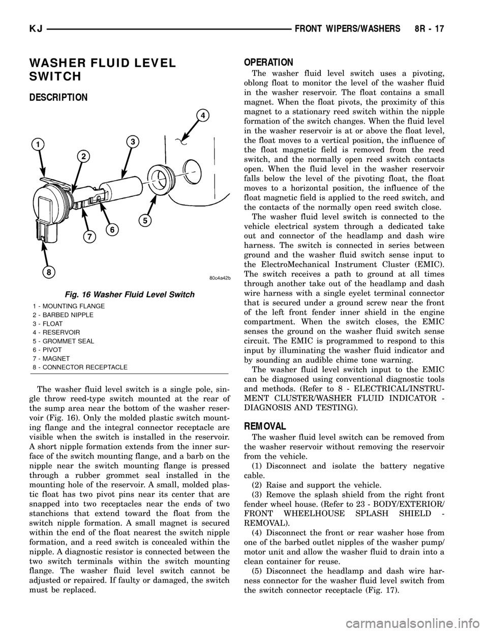
The washer fluid level switch is a single pole, sin-
gle throw reed-type switch mounted at the rear of
the sump area near the bottom of the washer reser-
voir (Fig. 16). Only the molded plastic switch mount-
ing flange and the integral connector receptacle are
visible when the switch is installed in the reservoir.
A short nipple formation extends from the inner sur-
face of the switch mounting flange, and a barb on the
nipple near the switch mounting flange is pressed
through a rubber grommet seal installed in the
mounting hole of the reservoir. A small, molded plas-
tic float has two pivot pins near its center that are
snapped into two receptacles near the ends of two
stanchions that extend toward the float from the
switch nipple formation. A small magnet is secured
within the end of the float nearest the switch nipple
formation, and a reed switch is concealed within the
nipple. A diagnostic resistor is connected between the
two switch terminals within the switch mounting
flange. The washer fluid level switch cannot be
adjusted or repaired. If faulty or damaged, the switch
must be replaced.
OPERATION
The washer fluid level switch uses a pivoting,
oblong float to monitor the level of the washer fluid
in the washer reservoir. The float contains a small
magnet. When the float pivots, the proximity of this
magnet to a stationary reed switch within the nipple
formation of the switch changes. When the fluid level
in the washer reservoir is at or above the float level,
the float moves to a vertical position, the influence of
the float magnetic field is removed from the reed
switch, and the normally open reed switch contacts
open. When the fluid level in the washer reservoir
falls below the level of the pivoting float, the float
moves to a horizontal position, the influence of the
float magnetic field is applied to the reed switch, and
the contacts of the normally open reed switch close.
The washer fluid level switch is connected to the
vehicle electrical system through a dedicated take
out and connector of the headlamp and dash wire
harness. The switch is connected in series between
ground and the washer fluid switch sense input to
the ElectroMechanical Instrument Cluster (EMIC).
The switch receives a path to ground at all times
through another take out of the headlamp and dash
wire harness with a single eyelet terminal connector
that is secured under a ground screw near the front
of the left front fender inner shield in the engine
compartment. When the switch closes, the EMIC
senses the ground on the washer fluid switch sense
circuit. The EMIC is programmed to respond to this
input by illuminating the washer fluid indicator and
by sounding an audible chime tone warning.
The washer fluid level switch input to the EMIC
can be diagnosed using conventional diagnostic tools
and methods. (Refer to 8 - ELECTRICAL/INSTRU-
MENT CLUSTER/WASHER FLUID INDICATOR -
DIAGNOSIS AND TESTING).
REMOVAL
The washer fluid level switch can be removed from
the washer reservoir without removing the reservoir
from the vehicle.
(1) Disconnect and isolate the battery negative
cable.
(2) Raise and support the vehicle.
(3) Remove the splash shield from the right front
fender wheel house. (Refer to 23 - BODY/EXTERIOR/
FRONT WHEELHOUSE SPLASH SHIELD -
REMOVAL).
(4) Disconnect the front or rear washer hose from
one of the barbed outlet nipples of the washer pump/
motor unit and allow the washer fluid to drain into a
clean container for reuse.
(5) Disconnect the headlamp and dash wire har-
ness connector for the washer fluid level switch from
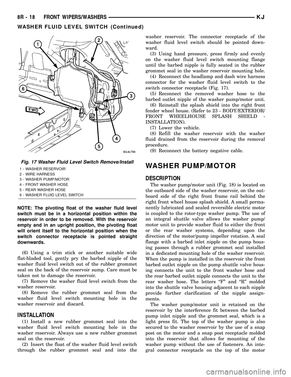
the switch connector receptacle (Fig. 17).
Fig. 16 Washer Fluid Level Switch
1 - MOUNTING FLANGE
2 - BARBED NIPPLE
3 - FLOAT
4 - RESERVOIR
5 - GROMMET SEAL
6 - PIVOT
7 - MAGNET
8 - CONNECTOR RECEPTACLE
KJFRONT WIPERS/WASHERS 8R - 17
Page 719 of 1803
NOTE: The pivoting float of the washer fluid level
switch must be in a horizontal position within the
reservoir in order to be removed. With the reservoir
empty and in an upright position, the pivoting float
will orient itself to the horizontal position when the
switch connector receptacle is pointed straight
downwards.
(6) Using a trim stick or another suitable wide
flat-bladed tool, gently pry the barbed nipple of the
washer fluid level switch out of the rubber grommet
seal on the back of the reservoir sump. Care must be
taken not to damage the reservoir.
(7) Remove the washer fluid level switch from the
washer reservoir.
(8) Remove the rubber grommet seal from the
washer fluid level switch mounting hole in the
washer reservoir and discard.
INSTALLATION
(1) Install a new rubber grommet seal into the
washer fluid level switch mounting hole in the
washer reservoir. Always use a new rubber grommet
seal on the reservoir.
(2) Insert the float of the washer fluid level switch
through the rubber grommet seal and into thewasher reservoir. The connector receptacle of the
washer fluid level switch should be pointed down-
ward.
(3) Using hand pressure, press firmly and evenly
on the washer fluid level switch mounting flange
until the barbed nipple is fully seated in the rubber
grommet seal in the washer reservoir mounting hole.
(4) Reconnect the headlamp and dash wire harness
connector for the washer fluid level switch to the
switch connector receptacle (Fig. 17).
(5) Reconnect the removed washer hose to the
barbed outlet nipple of the washer pump/motor unit.
(6) Reinstall the splash shield into the right front
fender wheel house. (Refer to 23 - BODY/EXTERIOR/
FRONT WHEELHOUSE SPLASH SHIELD -
INSTALLATION).
(7) Lower the vehicle.
(8) Refill the washer reservoir with the washer
fluid drained from the reservoir during the removal
procedure.
(9) Reconnect the battery negative cable.
WASHER PUMP/MOTOR
DESCRIPTION
The washer pump/motor unit (Fig. 18) is located on
the outboard side of the washer reservoir, on the out-
board side of the right front frame rail behind the
right front wheel house splash shield. A small perma-
nently lubricated and sealed reversible electric motor
is coupled to the rotor-type washer pump. The use of
an integral shuttle valve allows the washer pump/
motor unit to provide washer fluid to either the front
or the rear washer systems, depending upon the
direction of the motor/pump impeller rotation. A seal
flange with a barbed inlet nipple on the pump hous-
ing passes through a rubber grommet seal installed
in a dedicated mounting hole of the washer reservoir.
When the pump is installed in the reservoir the front
barbed outlet nipple on the pump shuttle valve hous-
ing connects the unit to the front washer hose and
the rear barbed outlet nipple connects the unit to the
rear washer hose. The letters ªFº and ªRº molded
into the shuttle valve housing adjacent to each nipple
provide further clarification of the nipple assign-
ments.
The washer pump/motor unit is retained on the
reservoir by the interference fit between the barbed
pump inlet nipple and the grommet seal, which is a
light press fit. The top of the washer pump is also
secured to the washer reservoir by the use of a snap
post on the motor and a snap post receptacle molded
into the reservoir that allows for mounting of the
washer pump without the use of fasteners. An inte-
gral connector receptacle on the top of the motor
Fig. 17 Washer Fluid Level Switch Remove/Install
1 - WASHER RESERVOIR
2 - WIRE HARNESS
3 - WASHER PUMP/MOTOR
4 - FRONT WASHER HOSE
5 - REAR WASHER HOSE
6 - WASHER FLUID LEVEL SWITCH
8R - 18 FRONT WIPERS/WASHERSKJ
WASHER FLUID LEVEL SWITCH (Continued)
Page 721 of 1803
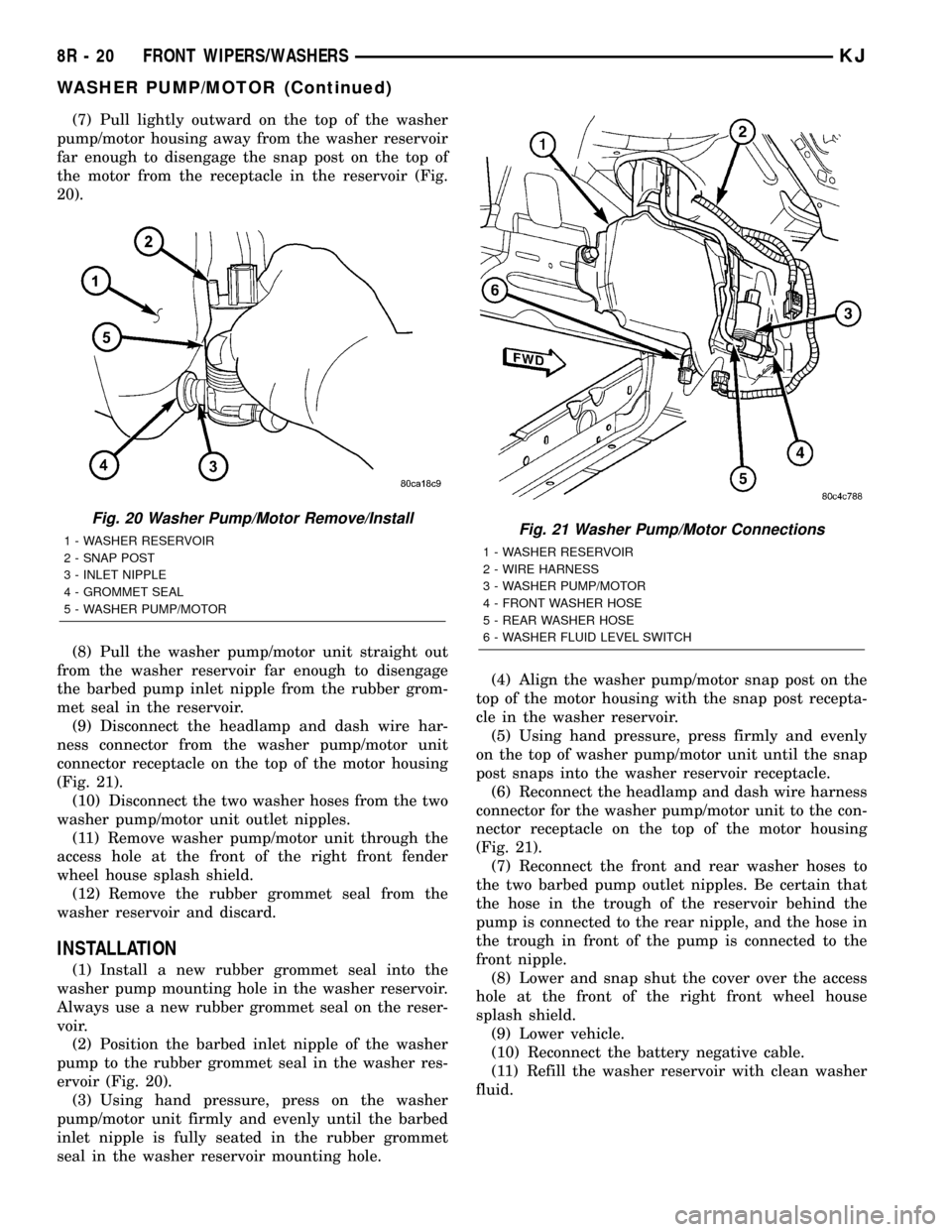
(7) Pull lightly outward on the top of the washer
pump/motor housing away from the washer reservoir
far enough to disengage the snap post on the top of
the motor from the receptacle in the reservoir (Fig.
20).
(8) Pull the washer pump/motor unit straight out
from the washer reservoir far enough to disengage
the barbed pump inlet nipple from the rubber grom-
met seal in the reservoir.
(9) Disconnect the headlamp and dash wire har-
ness connector from the washer pump/motor unit
connector receptacle on the top of the motor housing
(Fig. 21).
(10) Disconnect the two washer hoses from the two
washer pump/motor unit outlet nipples.
(11) Remove washer pump/motor unit through the
access hole at the front of the right front fender
wheel house splash shield.
(12) Remove the rubber grommet seal from the
washer reservoir and discard.
INSTALLATION
(1) Install a new rubber grommet seal into the
washer pump mounting hole in the washer reservoir.
Always use a new rubber grommet seal on the reser-
voir.
(2) Position the barbed inlet nipple of the washer
pump to the rubber grommet seal in the washer res-
ervoir (Fig. 20).
(3) Using hand pressure, press on the washer
pump/motor unit firmly and evenly until the barbed
inlet nipple is fully seated in the rubber grommet
seal in the washer reservoir mounting hole.(4) Align the washer pump/motor snap post on the
top of the motor housing with the snap post recepta-
cle in the washer reservoir.
(5) Using hand pressure, press firmly and evenly
on the top of washer pump/motor unit until the snap
post snaps into the washer reservoir receptacle.
(6) Reconnect the headlamp and dash wire harness
connector for the washer pump/motor unit to the con-
nector receptacle on the top of the motor housing
(Fig. 21).
(7) Reconnect the front and rear washer hoses to
the two barbed pump outlet nipples. Be certain that
the hose in the trough of the reservoir behind the
pump is connected to the rear nipple, and the hose in
the trough in front of the pump is connected to the
front nipple.
(8) Lower and snap shut the cover over the access
hole at the front of the right front wheel house
splash shield.
(9) Lower vehicle.
(10) Reconnect the battery negative cable.
(11) Refill the washer reservoir with clean washer
fluid.
Fig. 20 Washer Pump/Motor Remove/Install
1 - WASHER RESERVOIR
2 - SNAP POST
3 - INLET NIPPLE
4 - GROMMET SEAL
5 - WASHER PUMP/MOTORFig. 21 Washer Pump/Motor Connections
1 - WASHER RESERVOIR
2 - WIRE HARNESS
3 - WASHER PUMP/MOTOR
4 - FRONT WASHER HOSE
5 - REAR WASHER HOSE
6 - WASHER FLUID LEVEL SWITCH
8R - 20 FRONT WIPERS/WASHERSKJ
WASHER PUMP/MOTOR (Continued)
Page 722 of 1803
WASHER RESERVOIR
DESCRIPTION
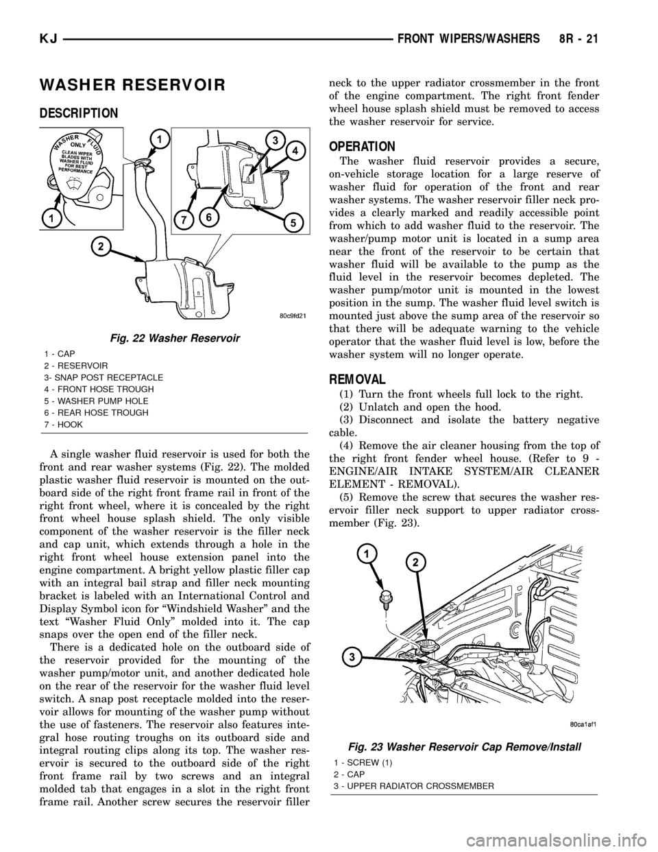
A single washer fluid reservoir is used for both the
front and rear washer systems (Fig. 22). The molded
plastic washer fluid reservoir is mounted on the out-
board side of the right front frame rail in front of the
right front wheel, where it is concealed by the right
front wheel house splash shield. The only visible
component of the washer reservoir is the filler neck
and cap unit, which extends through a hole in the
right front wheel house extension panel into the
engine compartment. A bright yellow plastic filler cap
with an integral bail strap and filler neck mounting
bracket is labeled with an International Control and
Display Symbol icon for ªWindshield Washerº and the
text ªWasher Fluid Onlyº molded into it. The cap
snaps over the open end of the filler neck.
There is a dedicated hole on the outboard side of
the reservoir provided for the mounting of the
washer pump/motor unit, and another dedicated hole
on the rear of the reservoir for the washer fluid level
switch. A snap post receptacle molded into the reser-
voir allows for mounting of the washer pump without
the use of fasteners. The reservoir also features inte-
gral hose routing troughs on its outboard side and
integral routing clips along its top. The washer res-
ervoir is secured to the outboard side of the right
front frame rail by two screws and an integral
molded tab that engages in a slot in the right front
frame rail. Another screw secures the reservoir fillerneck to the upper radiator crossmember in the front
of the engine compartment. The right front fender
wheel house splash shield must be removed to access
the washer reservoir for service.
OPERATION
The washer fluid reservoir provides a secure,
on-vehicle storage location for a large reserve of
washer fluid for operation of the front and rear
washer systems. The washer reservoir filler neck pro-
vides a clearly marked and readily accessible point
from which to add washer fluid to the reservoir. The
washer/pump motor unit is located in a sump area
near the front of the reservoir to be certain that
washer fluid will be available to the pump as the
fluid level in the reservoir becomes depleted. The
washer pump/motor unit is mounted in the lowest
position in the sump. The washer fluid level switch is
mounted just above the sump area of the reservoir so
that there will be adequate warning to the vehicle
operator that the washer fluid level is low, before the
washer system will no longer operate.
REMOVAL
(1) Turn the front wheels full lock to the right.
(2) Unlatch and open the hood.
(3) Disconnect and isolate the battery negative
cable.
(4) Remove the air cleaner housing from the top of
the right front fender wheel house. (Refer to 9 -
ENGINE/AIR INTAKE SYSTEM/AIR CLEANER
ELEMENT - REMOVAL).
(5) Remove the screw that secures the washer res-
ervoir filler neck support to upper radiator cross-
member (Fig. 23).
Fig. 22 Washer Reservoir
1 - CAP
2 - RESERVOIR
3- SNAP POST RECEPTACLE
4 - FRONT HOSE TROUGH
5 - WASHER PUMP HOLE
6 - REAR HOSE TROUGH
7 - HOOK
Fig. 23 Washer Reservoir Cap Remove/Install
1 - SCREW (1)
2 - CAP
3 - UPPER RADIATOR CROSSMEMBER
KJFRONT WIPERS/WASHERS 8R - 21
Page 723 of 1803
(6) Raise and support the vehicle.
(7) Remove the splash shield from the right front
fender wheel house. (Refer to 23 - BODY/EXTERIOR/
WHEELHOUSE SPLASH SHIELD - REMOVAL).
(8) Release the ªWº clip that secures the front
bumper fascia to the front bumper support. This clip
is located behind the bumper support and below the
right front lamp unit.
(9) Place a clean container on the floor beneath the
washer pump/motor location to catch any washer
fluid that is spilled during the following procedure.
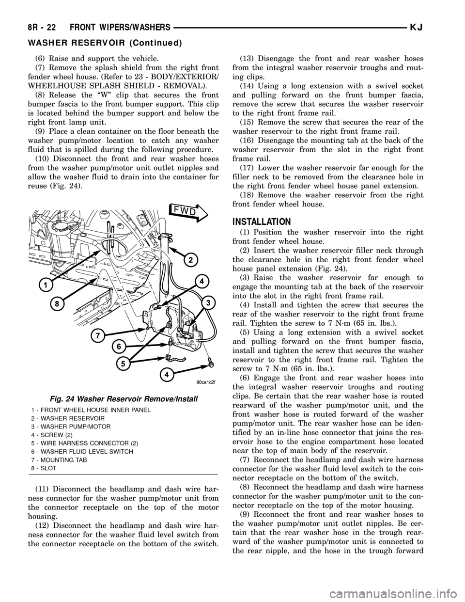
(10) Disconnect the front and rear washer hoses
from the washer pump/motor unit outlet nipples and
allow the washer fluid to drain into the container for
reuse (Fig. 24).
(11) Disconnect the headlamp and dash wire har-
ness connector for the washer pump/motor unit from
the connector receptacle on the top of the motor
housing.
(12) Disconnect the headlamp and dash wire har-
ness connector for the washer fluid level switch from
the connector receptacle on the bottom of the switch.(13) Disengage the front and rear washer hoses
from the integral washer reservoir troughs and rout-
ing clips.
(14) Using a long extension with a swivel socket
and pulling forward on the front bumper fascia,
remove the screw that secures the washer reservoir
to the right front frame rail.
(15) Remove the screw that secures the rear of the
washer reservoir to the right front frame rail.
(16) Disengage the mounting tab at the back of the
washer reservoir from the slot in the right front
frame rail.
(17) Lower the washer reservoir far enough for the
filler neck to be removed from the clearance hole in
the right front fender wheel house panel extension.
(18) Remove the washer reservoir from the right
front fender wheel house.
INSTALLATION
(1) Position the washer reservoir into the right
front fender wheel house.
(2) Insert the washer reservoir filler neck through
the clearance hole in the right front fender wheel
house panel extension (Fig. 24).
(3) Raise the washer reservoir far enough to
engage the mounting tab at the back of the reservoir
into the slot in the right front frame rail.
(4) Install and tighten the screw that secures the
rear of the washer reservoir to the right front frame
rail. Tighten the screw to 7 N´m (65 in. lbs.).
(5) Using a long extension with a swivel socket
and pulling forward on the front bumper fascia,
install and tighten the screw that secures the washer
reservoir to the right front frame rail. Tighten the
screw to 7 N´m (65 in. lbs.).
(6) Engage the front and rear washer hoses into
the integral washer reservoir troughs and routing
clips. Be certain that the rear washer hose is routed
rearward of the washer pump/motor unit, and the
front washer hose is routed forward of the washer
pump/motor unit. The rear washer hose can be iden-
tified by an in-line hose connector that joins the res-
ervoir hose to the engine compartment hose located
near the top of main body of the reservoir.
(7) Reconnect the headlamp and dash wire harness
connector for the washer fluid level switch to the con-
nector receptacle on the bottom of the switch.
(8) Reconnect the headlamp and dash wire harness
connector for the washer pump/motor unit to the con-
nector receptacle on the top of the motor housing.
(9) Reconnect the front and rear washer hoses to
the washer pump/motor unit outlet nipples. Be cer-
tain that the rear washer hose in the trough rear-
ward of the washer pump/motor unit is connected to
the rear nipple, and the hose in the trough forward
Fig. 24 Washer Reservoir Remove/Install
1 - FRONT WHEEL HOUSE INNER PANEL
2 - WASHER RESERVOIR
3 - WASHER PUMP/MOTOR
4 - SCREW (2)
5 - WIRE HARNESS CONNECTOR (2)
6 - WASHER FLUID LEVEL SWITCH
7 - MOUNTING TAB
8 - SLOT
8R - 22 FRONT WIPERS/WASHERSKJ
WASHER RESERVOIR (Continued)
Page 724 of 1803

of the washer pump/motor unit is connected to the
front nipple.
(10) Engage the ªWº clip that secures the front
bumper fascia to the front bumper support. This clip
is located behind the bumper support and below the
right front lamp unit.
(11) Reinstall the splash shield into the right front
fender wheel house. (Refer to 23 - BODY/EXTERIOR/
WHEELHOUSE SPLASH SHIELD - INSTALLA-
TION).
(12) Lower the vehicle.
(13) Install and tighten the screw that secures the
washer reservoir filler neck support to upper radiator
crossmember (Fig. 23). Tighten the screw to 7 N´m
(65 in. lbs.).
(14) Reinstall the air cleaner housing onto the top
of the right front fender wheel house. (Refer to 9 -
ENGINE/AIR INTAKE SYSTEM/AIR CLEANER
ELEMENT - INSTALLATION).
(15) Refill the washer reservoir with the washer
fluid drained from the reservoir during the removal
procedure.
(16) Reconnect the battery negative cable.
WIPER HIGH/LOW RELAY
DESCRIPTION
The wiper high/low relay is located in the Power
Distribution Center (PDC) in the engine compart-
ment near the battery. The wiper high/low relay is a
conventional International Standards Organization
(ISO) micro relay (Fig. 25). Relays conforming to theISO specifications have common physical dimensions,
current capacities, terminal patterns, and terminal
functions. The relay is contained within a small, rect-
angular, molded plastic housing and is connected to
all of the required inputs and outputs by five integral
male spade-type terminals that extend from the bot-
tom of the relay base.
The wiper high/low relay cannot be adjusted or
repaired and, if faulty or damaged, the unit must be
replaced.
OPERATION
The wiper high/low relay is an electromechanical
switch that uses a low current input from the Body
Control Module (BCM) to control a high current out-
put to the front wiper motor. The movable common
feed contact point is held against the fixed normally
closed contact point by spring pressure. When the
relay coil is energized, an electromagnetic field is
produced by the coil windings. This electromagnetic
field draws the movable relay contact point away
from the fixed normally closed contact point, and
holds it against the fixed normally open contact
point. When the relay coil is de-energized, spring
pressure returns the movable contact point back
against the fixed normally closed contact point. A
resistor is connected in parallel with the relay coil in
the relay, and helps to dissipate voltage spikes and
electromagnetic interference that can be generated as
the electromagnetic field of the relay coil collapses.
The wiper high/low relay terminals are connected
to the vehicle electrical system through a connector
receptacle in the Power Distribution Center (PDC).
The inputs and outputs of the wiper high/low relay
include:
²Common Feed Terminal- The common feed
terminal (30) is connected to the output of the wiper
on/off relay at all times through the wiper on/off
relay output circuit.
²Coil Ground Terminal- The coil ground termi-
nal (85) is connected to a control output of the Body
Control Module (BCM) through a front wiper high/
low relay control circuit. The BCM controls front
wiper motor operation by controlling a ground path
through this circuit.
²Coil Battery Terminal- The coil battery ter-
minal (86) receives battery current at all times from
a circuit breaker in the Junction Block (JB) through
a fused ignition switch output (run-acc) circuit.
²Normally Open Terminal- The normally open
terminal (87) is connected to the high speed brush of
the front wiper motor through a front wiper high/low
relay high speed output circuit, and is connected to
the high speed brush whenever the relay is ener-
gized.
Fig. 25 ISO Micro Relay
30 - COMMON FEED
85 - COIL GROUND
86 - COIL BATTERY
87 - NORMALLY OPEN
87A - NORMALLY CLOSED
KJFRONT WIPERS/WASHERS 8R - 23
WASHER RESERVOIR (Continued)
Page 736 of 1803
(5) Remove the rear check valve and rear washer
nozzle hose as a unit through the CHMSL mounting
hole.
(6) Disconnect the rear washer nozzle hose from
the barbed nipple of the rear check valve.
INSTALLATION
(1) Reconnect the rear washer nozzle hose to the
barbed nipple of the rear check valve. Be certain that
the flow direction arrow molded into the rear check
valve body is oriented towards the rear washer noz-
zle hose.
WARNING: THE EDGES OF THE SHEET METAL
AROUND THE CENTER HIGH MOUNTED STOP
LAMP MOUNTING HOLE IN THE ROOF PANEL.
TAKE THE PROPER PRECAUTIONS TO AVOID PER-
SONAL INJURY.
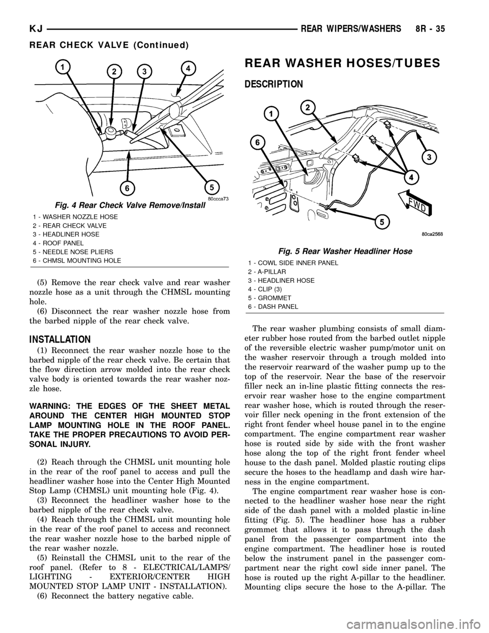
(2) Reach through the CHMSL unit mounting hole
in the rear of the roof panel to access and pull the
headliner washer hose into the Center High Mounted
Stop Lamp (CHMSL) unit mounting hole (Fig. 4).
(3) Reconnect the headliner washer hose to the
barbed nipple of the rear check valve.
(4) Reach through the CHMSL unit mounting hole
in the rear of the roof panel to access and reconnect
the rear washer nozzle hose to the barbed nipple of
the rear washer nozzle.
(5) Reinstall the CHMSL unit to the rear of the
roof panel. (Refer to 8 - ELECTRICAL/LAMPS/
LIGHTING - EXTERIOR/CENTER HIGH
MOUNTED STOP LAMP UNIT - INSTALLATION).
(6) Reconnect the battery negative cable.
REAR WASHER HOSES/TUBES
DESCRIPTION
The rear washer plumbing consists of small diam-
eter rubber hose routed from the barbed outlet nipple
of the reversible electric washer pump/motor unit on
the washer reservoir through a trough molded into
the reservoir rearward of the washer pump up to the
top of the reservoir. Near the base of the reservoir
filler neck an in-line plastic fitting connects the res-
ervoir rear washer hose to the engine compartment
rear washer hose, which is routed through the reser-
voir filler neck opening in the front extension of the
right front fender wheel house panel in to the engine
compartment. The engine compartment rear washer
hose is routed side by side with the front washer
hose along the top of the right front fender wheel
house to the dash panel. Molded plastic routing clips
secure the hoses to the headlamp and dash wire har-
ness in the engine compartment.
The engine compartment rear washer hose is con-
nected to the headliner washer hose near the right
side of the dash panel with a molded plastic in-line
fitting (Fig. 5). The headliner hose has a rubber
grommet that allows it to pass through the dash
panel from the passenger compartment into the
engine compartment. The headliner hose is routed
below the instrument panel in the passenger com-
partment near the right cowl side inner panel. The
hose is routed up the right A-pillar to the headliner.
Mounting clips secure the hose to the A-pillar. The
Fig. 4 Rear Check Valve Remove/Install
1 - WASHER NOZZLE HOSE
2 - REAR CHECK VALVE
3 - HEADLINER HOSE
4 - ROOF PANEL
5 - NEEDLE NOSE PLIERS
6 - CHMSL MOUNTING HOLE
Fig. 5 Rear Washer Headliner Hose
1 - COWL SIDE INNER PANEL
2 - A-PILLAR
3 - HEADLINER HOSE
4 - CLIP (3)
5 - GROMMET
6 - DASH PANEL
KJREAR WIPERS/WASHERS 8R - 35
REAR CHECK VALVE (Continued)
Page 1161 of 1803
CONNECTOR NAME/NUMBER COLOR LOCATION FIG.
Left Front Door Ajar Switch (Base) BK In Left Front Door N/S
Left Front Door Lock Motor/Ajar
Switch (Except Base)BK In Left Front Door 41
Left Front Door Speaker BK Behind Left Front Door Panel 41
Left Front Impact Sensor BK Front Side of Engine
Compartment28
Left Front Park/Turn Signal Lamp BK Behind Left Turn Signal
LampN/S
Left Front Power Window Motor LG In Left Front Door 41
Left Front Wheel Speed Sensor BK Left Side of Engine
Compartment30
Left Headlamp (BUX) Behind Left Headlamp N/S
Left Headlamp (Except BUX) DB Behind Left Headlamp N/S
Left Heated Seat Assembly LG At Left Seat N/S
Left Heated Seat Switch BK At Left Seat N/S
Left Instrument Panel Lamp BK Left Side of Instrument Panel N/S
Left Instrument Panel Speaker BK Left Side of Instrument Panel 33, 37
Left Leveling Motor (BUX) BK At Left Headlamp N/S
Left Position Lamp (BUX) BK Left Front Side of Vehicle N/S
Left Power Mirror WT In Left Front Door 41
Left Power Seat Motors BK At Left Seat N/S
Left Power Seat Switch GN At Left Seat N/S
Left Rear Door Ajar Switch (Base) BK In Left Rear Door N/S
Left Rear Door Lock Motor/Ajar
Switch (Except Base)BK In Left Rear Door N/S
Left Rear Door Speaker In Left Rear Door
Left Rear Power Window Motor LG In Left Rear Door N/S
Left Remote Radio Switch BK On Steering Wheel N/S
Left Side Impact Airbag Control
Module (LSIACM)YL Left Lower B-Pillar 35, 38
Left Side Marker Lamp BK Left Front Fender N/S
Left Side Repeater Lamp (BUX) BK Left Front Fender N/S
Left Speed Control Switch BK On Steering Wheel N/S
Left Tail/Stop Lamp BK Left Rear Quarter Panel 45
Left Visor/Vanity Lamp WT Left Front of Headliner N/S
License Lamp (BUX) LG In Tailgate 46
License Lamp (Except BUX) LG On Bumper N/S
Line Pressure Sensor (3.7L) BK Right Side of Transmission 6
Low Note Horn BK Left Front Side of Engine
Compartment29
Manifold Absolute Pressure Sensor BK Front Side of Engine 2
Mass Air Flow Sensor (Diesel) Top of Engine 21
Multi-Function Switch C1 GY At Steering Column N/S
Multi-Function Switch C2 GY At Steering Column N/S
8Wa - 91 - 6 8W-91 CONNECTOR/GROUND/SPLICE LOCATIONKJ
CONNECTOR/GROUND/SPLICE LOCATION (Continued)
Page 1163 of 1803
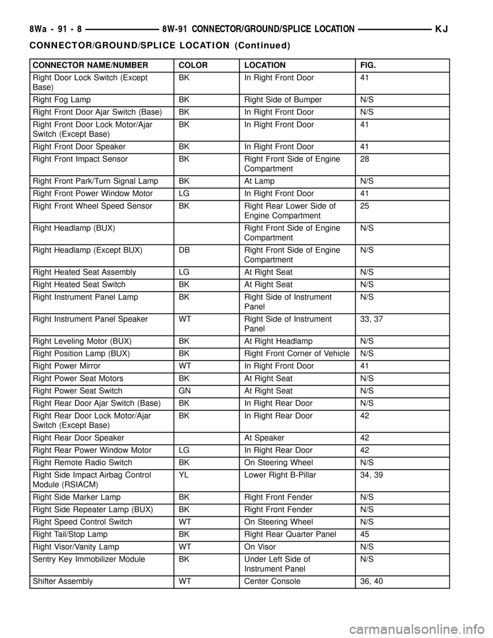
CONNECTOR NAME/NUMBER COLOR LOCATION FIG.
Right Door Lock Switch (Except
Base)BK In Right Front Door 41
Right Fog Lamp BK Right Side of Bumper N/S
Right Front Door Ajar Switch (Base) BK In Right Front Door N/S
Right Front Door Lock Motor/Ajar
Switch (Except Base)BK In Right Front Door 41
Right Front Door Speaker BK In Right Front Door 41
Right Front Impact Sensor BK Right Front Side of Engine
Compartment28
Right Front Park/Turn Signal Lamp BK At Lamp N/S
Right Front Power Window Motor LG In Right Front Door 41
Right Front Wheel Speed Sensor BK Right Rear Lower Side of
Engine Compartment25
Right Headlamp (BUX) Right Front Side of Engine
CompartmentN/S
Right Headlamp (Except BUX) DB Right Front Side of Engine
CompartmentN/S
Right Heated Seat Assembly LG At Right Seat N/S
Right Heated Seat Switch BK At Right Seat N/S
Right Instrument Panel Lamp BK Right Side of Instrument
PanelN/S
Right Instrument Panel Speaker WT Right Side of Instrument
Panel33, 37
Right Leveling Motor (BUX) BK At Right Headlamp N/S
Right Position Lamp (BUX) BK Right Front Corner of Vehicle N/S
Right Power Mirror WT In Right Front Door 41
Right Power Seat Motors BK At Right Seat N/S
Right Power Seat Switch GN At Right Seat N/S
Right Rear Door Ajar Switch (Base) BK In Right Rear Door N/S
Right Rear Door Lock Motor/Ajar
Switch (Except Base)BK In Right Rear Door 42
Right Rear Door Speaker At Speaker 42
Right Rear Power Window Motor LG In Right Rear Door 42
Right Remote Radio Switch BK On Steering Wheel N/S
Right Side Impact Airbag Control
Module (RSIACM)YL Lower Right B-Pillar 34, 39
Right Side Marker Lamp BK Right Front Fender N/S
Right Side Repeater Lamp (BUX) BK Right Front Fender N/S
Right Speed Control Switch WT On Steering Wheel N/S
Right Tail/Stop Lamp BK Right Rear Quarter Panel 45
Right Visor/Vanity Lamp WT On Visor N/S
Sentry Key Immobilizer Module BK Under Left Side of
Instrument PanelN/S
Shifter Assembly WT Center Console 36, 40
8Wa - 91 - 8 8W-91 CONNECTOR/GROUND/SPLICE LOCATIONKJ
CONNECTOR/GROUND/SPLICE LOCATION (Continued)