wheel torque JEEP LIBERTY 2002 KJ / 1.G Owner's Manual
[x] Cancel search | Manufacturer: JEEP, Model Year: 2002, Model line: LIBERTY, Model: JEEP LIBERTY 2002 KJ / 1.GPages: 1803, PDF Size: 62.3 MB
Page 141 of 1803

(10) Install axle vent hose.
(11) Install propeller shaft with reference marks.
(12) Install the wheels and tires.
(13) Add gear lubricant to specifications, if neces-
sary.
(14) Remove lifting device from axle and lower the
vehicle.
(15) Tighten the lower control arm bolts to torque
specification.
ADJUSTMENTS
Ring gears and pinions are supplied as matched
sets only. The identifying numbers for the ring gear
and pinion are etched/marked onto each gear (Fig. 8).
A plus (+) number, minus (±) number or zero (0) is
etched/marked on the face or shaft of the pinion. This
number is the amount (in thousandths of an inch)
the depth varies from the standard depth setting of a
pinion etched with a (0). The standard depth pro-
vides the best gear tooth contact pattern. Refer to
Backlash and Contact Pattern Analysis paragraph in
this section for additional information.
Compensation for pinion depth variance is
achieved with select shims. The shims are placed
behind the rear pinion bearing (Fig. 9).
If a new gear set is being installed, note the depth
variance etched into both the original and replace-
ment pinion. Add or subtract the thickness of the
original depth shims to compensate for the difference
in the depth variances. Refer to the Depth Variance
chart.
Note where Old and New Pinion Marking columns
intersect. Intersecting figure represents plus or
minus the amount needed.Note the etched number on the face of the pinion
gear head (±1, ±2, 0, +1, +2, etc.). The numbers rep-
resent thousands of an inch deviation from the stan-
dard. If the number is negative, add that value to the
required thickness of the depth shims. If the number
is positive, subtract that value from the thickness of
the depth shim. If the number is 0 no change is nec-
essary.
Fig. 7 LOWER SUSPENSION ARM
1 - AXLE BRACKET BOLT
2 - LOWER CONTROL ARM
3 - BODY BRACKET BOLT
Fig. 8 Pinion Gear ID Numbers - Typical
1 - PRODUCTION NUMBERS
2 - DRIVE PINION GEAR DEPTH VARIANCE
3 - GEAR MATCHING NUMBER (SAME AS RING GEAR
NUMBER)
Fig. 9 Adjustment Shim Locations
1 - DIFFERENTIAL HOUSING
2 - COLLAPSIBLE SPACER
3 - REAR PINION BEARING
4 - PINION DEPTH SHIM
5 - PINION GEAR
6 - BEARING CUP
3 - 92 REAR AXLE-81/4KJ
REAR AXLE - 8 1/4 (Continued)
Page 153 of 1803

lbs.) increments until proper rotating torque is
achieved.
NOTE: The bearing rotating torque should be con-
stant during a complete revolution of the pinion. If
the rotating torque varies, it indicates a binding
condition.
(9) The seal replacement is unacceptable if the
final pinion nut torque is less than 285 N´m (210 ft.
lbs.).
(10) Install the propeller shaft with the installa-
tion reference marks aligned.
(11) Install the brake drums.
(12) Check the differential housing lubricant level.
(13) Install wheel and tire assemblies and lower
the vehicle.
DIFFERENTIAL
REMOVAL
(1) Raise and support vehicle.
(2) Remove fill hole plug from the differential
housing cover.
(3) Remove differential housing cover and drain
housing.
(4) Clean the housing cavity with a flushing oil,
light engine oil or lint free cloth.Do not use water,
steam, kerosene or gasoline for cleaning.(5) Remove the axle shafts.
NOTE: Side play resulting from bearing races being
loose on case hubs requires replacement of the dif-
ferential case.
(6) Mark the differential housing and bearing caps
for installation reference (Fig. 28).
(7) Remove bearing threaded adjuster locks from
each bearing cap.
(8) Loosen bearing cap bolts, them loosen the
threaded adjusters with Wrench C-4164 (Fig. 29).
Fig. 27 Pinion Rotation Torque
1 - PINION YOKE
2 - INCH POUND TORQUE WRENCH
Fig. 28 Reference Mark
1 - REFERENCE MARKS
2 - REFERENCE MARKS
3 - DIFFERENTIAL HOUSING
4 - BEARING CAP
Fig. 29 Threaded Adjuster
1 - AXLE TUBE
2 - BACKING PLATE
3 - THREAD ADJUSTER WRENCH
3 - 104 REAR AXLE-81/4KJ
PINION SEAL (Continued)
Page 155 of 1803

(6) Install adjuster locks on the bearing caps.
(7) Install axle shafts.
(8) Apply a bead of red Mopar silicone rubber axle
sealant or equivalent to the housing cover (Fig. 33).
CAUTION: If cover is not installed within 3 to 5 min-
utes, the cover must be cleaned and new RTV
applied or adhesion quality will be compromised.
(9) Install cover and tighten bolts in a criss-cross
pattern to 41 N´m (30 ft. lbs.).
(10) Fill differential with gear lubricant to bottom
of the fill plug hole.
(11) Install the fill hole plug.
(12) Install wheel and tire assemblies.
(13) Remove support and lower vehicle.
(14) Trac-loktdifferential equipped vehicles should
be road tested by making 10 to 12 slow figure-eight
turns. This maneuver will pump the lubricant
through the clutch discs to eliminate a possible chat-
ter noise complaint.DIFFERENTIAL - TRAC-LOK
DIAGNOSIS AND TESTING - TRAC-LOKT
The most common problem is a chatter noise when
turning corners. Before removing the unit for repair,
drain, flush and refill the axle with the specified
lubricant. A container of Mopar Trac-loktLubricant
(friction modifier) should be added after repair ser-
vice or during a lubricant change.
After changing the lubricant, drive the vehicle and
make 10 to 12 slow, figure-eight turns. This maneu-
ver will pump lubricant through the clutches. This
will correct the condition in most instances. If the
chatter persists, clutch damage could have occurred.
DIFFERENTIAL TEST
The differential can be tested without removing the
differential case by measuring rotating torque. Make
sure brakes are not dragging during this measure-
ment.
(1) Place blocks in front and rear of both front
wheels.
(2) Raise one rear wheel until it is completely off
the ground.
(3) Engine off, transmission in neutral, and park-
ing brake off.
(4) Remove wheel and bolt Special Tool 6790 or
equivalent tool to studs.
(5) Use torque wrench on special tool to rotate
wheel and read rotating torque (Fig. 34).
(6) If rotating torque is less than 41 N´m (56 ft.
lbs.) or more than 271 N´m (200 ft. lbs.) on either
wheel the unit should be serviced.
Fig. 33 Differential Cover Sealant
1 - SEALANT
2 - DIFFERNTIAL COVER
Fig. 34 ROTATING TORQUE TEST
1 - SPECIAL TOOL WITH BOLT IN CENTER HOLE
2 - TORQUE WRENCH
3 - 106 REAR AXLE-81/4KJ
DIFFERENTIAL (Continued)
Page 164 of 1803

(15) Invert the differential case.
(16) Install ring gear on the differential case and
start two ring gear bolts. This will provide case-to-
ring gear bolt hole alignment.
(17) Invert the differential case in the vise.
(18) Installnewring gear bolts and alternately
tighten to 102 N´m (75 ft. lbs.) (Fig. 60).
CAUTION: Never reuse the ring gear bolts. The
bolts can fracture causing extensive damage.
(19) Install differential in axle housing and verify
gear mesh refer to Adjustments (Gear Contact Pat-
tern).
(20) Install differential cover fill with gear lubri-
cant.
(21) Install the propeller shaft with reference
marks aligned.
(22) Install wheel and tire assemblies and lower
the vehicle.
Fig. 60 Ring Gear
1 - TORQUE WRENCH
2 - BOLTS
3 - RING GEAR
4 - DIFFERENTIAL CASE
KJREAR AXLE - 8 1/4 3 - 115
PINION GEAR/RING GEAR/TONE RING (Continued)
Page 171 of 1803
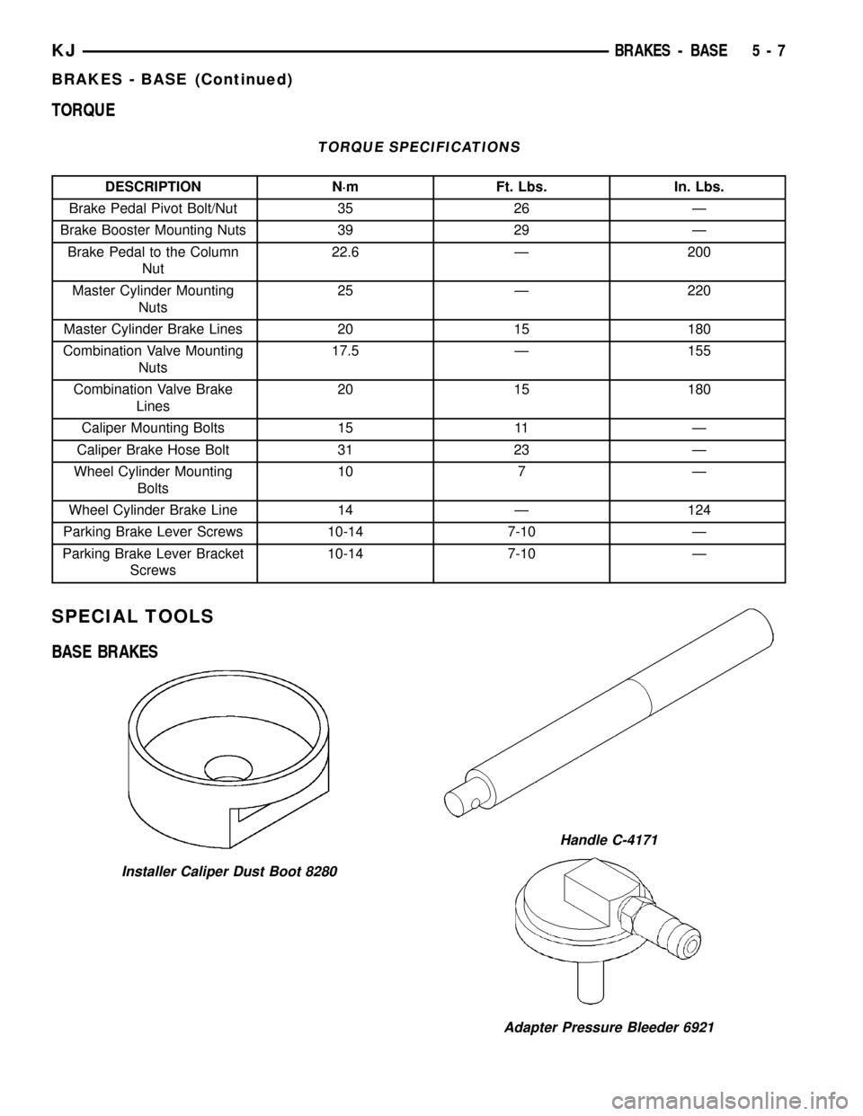
TORQUE
TORQUE SPECIFICATIONS
DESCRIPTION N´m Ft. Lbs. In. Lbs.
Brake Pedal Pivot Bolt/Nut 35 26 Ð
Brake Booster Mounting Nuts 39 29 Ð
Brake Pedal to the Column
Nut22.6 Ð 200
Master Cylinder Mounting
Nuts25 Ð 220
Master Cylinder Brake Lines 20 15 180
Combination Valve Mounting
Nuts17.5 Ð 155
Combination Valve Brake
Lines20 15 180
Caliper Mounting Bolts 15 11 Ð
Caliper Brake Hose Bolt 31 23 Ð
Wheel Cylinder Mounting
Bolts10 7 Ð
Wheel Cylinder Brake Line 14 Ð 124
Parking Brake Lever Screws 10-14 7-10 Ð
Parking Brake Lever Bracket
Screws10-14 7-10 Ð
SPECIAL TOOLS
BASE BRAKES
Installer Caliper Dust Boot 8280
Handle C-4171
Adapter Pressure Bleeder 6921
KJBRAKES - BASE 5 - 7
BRAKES - BASE (Continued)
Page 172 of 1803

BRAKE LINES
DESCRIPTION
Flexible rubber hose is used at both front brakes
and at the rear axle junction block. Double walled
steel tubing is used to connect the master cylinder to
the major hydraulic braking components and then to
the flexible rubber hoses. Double inverted style and
ISO style flares are used on the brake lines.
DIAGNOSIS AND TESTING - BRAKE LINE AND
HOSES
Flexible rubber hose is used at both front brakes
and at the rear axle junction block. Inspect the hoses
whenever the brake system is serviced, at every
engine oil change, or whenever the vehicle is in for
service.
Inspect the hoses for surface cracking, scuffing, or
worn spots. Replace any brake hose immediately if
the fabric casing of the hose is exposed due to cracks
or abrasions.
Also check brake hose installation. Faulty installa-
tion can result in kinked, twisted hoses, or contact
with the wheels and tires or other chassis compo-
nents. All of these conditions can lead to scuffing,
cracking and eventual failure.
The steel brake lines should be inspected periodi-
cally for evidence of corrosion, twists, kinks, leaks, or
other damage. Heavily corroded lines will eventually
rust through causing leaks. In any case, corroded or
damaged brake lines should be replaced.
Factory replacement brake lines and hoses are rec-
ommended to ensure quality, correct length and supe-
rior fatigue life. Care should be taken to make sure
that brake line and hose mating surfaces are clean
and free from nicks and burrs. Also remember that
right and left brake hoses are not interchangeable.
Use new copper seal washers at all caliper connec-
tions. Be sure brake line connections are properly
made (not cross threaded) and tightened to recom-
mended torque.
STANDARD PROCEDURE
STANDARD PROCEDURE - DOUBLE INVERTED
FLARING
A preformed metal brake tube is recommended and
preferred for all repairs. However, double-wall steel
tube can be used for emergency repair when factory
replacement parts are not readily available.
Special bending tools are needed to avoid kinking
or twisting of metal brake tubes. Special flaring tools
are needed to make a double inverted flare or ISO
flare.(1) Cut off damaged tube with Tubing Cutter.
(2) Ream cut edges of tubing to ensure proper
flare.
(3) Install replacement tube nut on the tube.
(4) Insert tube in flaring tool.
(5) Place gauge form over the end of the tube.
(6) Push tubing through flaring tool jaws until
tube contacts recessed notch in gauge that matches
tube diameter.
(7) Tighten the tool bar on the tube
(8) Insert plug on gauge in the tube. Then swing
compression disc over gauge and center tapered flar-
ing screw in recess of compression disc (Fig. 2).
(9) Tighten tool handle until plug gauge is
squarely seated on jaws of flaring tool. This will start
the inverted flare.
(10) Remove the plug gauge and complete the
inverted flare.
STANDARD PROCEDURE - ISO FLARING
A preformed metal brake tube is recommended and
preferred for all repairs. However, double-wall steel
tube can be used for emergency repair when factory
replacement parts are not readily available.
Special bending tools are needed to avoid kinking
or twisting of metal brake tubes. Special flaring tools
are needed to make a double inverted flare or ISO
flare.
To make a ISO flare use a ISO brake flaring tool or
equivalent.
(1) Cut off damaged tube with Tubing Cutter.
(2) Remove any burrs from the inside of the tube.
(3) Install tube nut on the tube.
Fig. 2 Inverted
5 - 8 BRAKES - BASEKJ
Page 197 of 1803
the rear brake circuit is pulsed. This allows fluid to
enter the low pressure accumulator (LPA) in the
HCU resulting in a drop in fluid pressure to the rear
brakes. In order to increase the rear brake pressure
the outlet valve is switched off and the inlet valve is
pulsed. This increases the pressure to the rear
brakes. This will continue until the required slip dif-
ference is obtained. At the end of EBD braking (no
brake application) the fluid in the LPA drains back to
the master cylinder by switching on the outlet valve
and draining through the inlet valve check valve. At
the same time the inlet valve is switched on to pre-
vent a hydraulic short circiut in case of another
brake application.The EBD will remain functional
during many ABS fault modes. If the red and amber
warning lamps are illuminated the EBD may have a
fault.
DIAGNOSIS AND TESTING - ANTILOCK
BRAKING SYSTEM
The ABS brake system performs several self-tests
every time the ignition switch is turned on and the
vehicle is driven. The CAB monitors the systems
input and output circuits to verify the system is oper-
ating correctly. If the on board diagnostic system
senses that a circuit is malfunctioning the system
will set a trouble code in its memory.
NOTE: An audible noise may be heard during the
self-test. This noise should be considered normal.NOTE: The MDS or DRB III scan tool is used to
diagnose the ABS system. For additional informa-
tion refer to the Electrical, Electronic Control Mod-
ules section. For test procedures refer to the
Chassis Diagnostic Manual.
STANDARD PROCEDURE - ABS BRAKE
BLEEDING
ABS system bleeding requires conventional bleed-
ing methods plus use of the DRB scan tool. The pro-
cedure involves performing a base brake bleeding,
followed by use of the scan tool to cycle and bleed the
HCU pump and solenoids. A second base brake bleed-
ing procedure is then required to remove any air
remaining in the system.
(1) Perform base brake bleeding,(Refer to 5 -
BRAKES - STANDARD PROCEDURE) OR (Refer to
5 - BRAKES - STANDARD PROCEDURE).
(2) Connect scan tool to the Data Link Connector.
(3) Select ANTILOCK BRAKES, followed by MIS-
CELLANEOUS, then ABS BRAKES. Follow the
instructions displayed. When scan tool displays TEST
COMPLETE, disconnect scan tool and proceed.
(4) Perform base brake bleeding a second time,(Re-
fer to 5 - BRAKES - STANDARD PROCEDURE) OR
(Refer to 5 - BRAKES - STANDARD PROCEDURE).
(5) Top off master cylinder fluid level and verify
proper brake operation before moving vehicle.
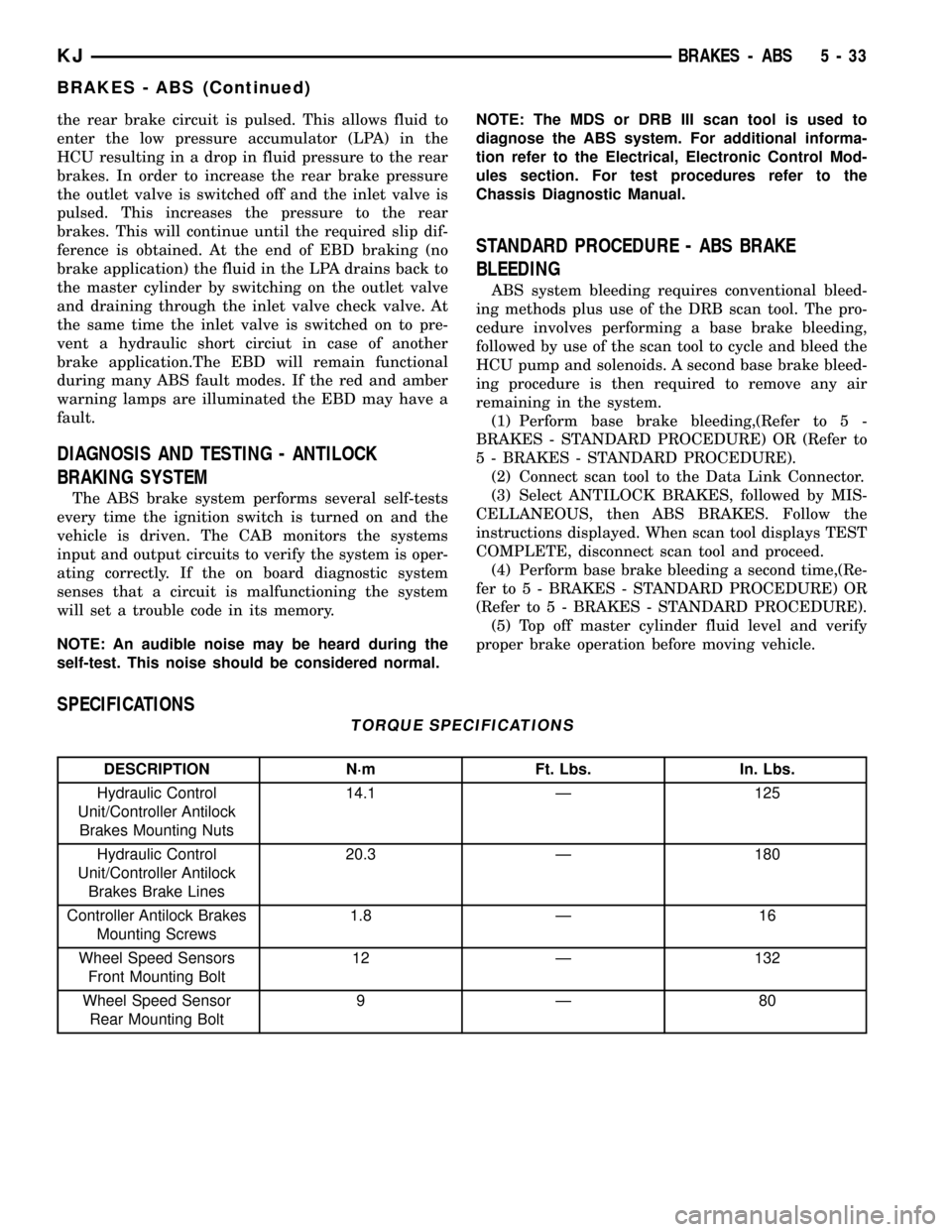
SPECIFICATIONS
TORQUE SPECIFICATIONS
DESCRIPTION N´m Ft. Lbs. In. Lbs.
Hydraulic Control
Unit/Controller Antilock
Brakes Mounting Nuts14.1 Ð 125
Hydraulic Control
Unit/Controller Antilock
Brakes Brake Lines20.3 Ð 180
Controller Antilock Brakes
Mounting Screws1.8 Ð 16
Wheel Speed Sensors
Front Mounting Bolt12 Ð 132
Wheel Speed Sensor
Rear Mounting Bolt9Ð80
KJBRAKES - ABS 5 - 33
BRAKES - ABS (Continued)
Page 205 of 1803

CLUTCH
TABLE OF CONTENTS
page page
CLUTCH
DESCRIPTION..........................1
OPERATION............................1
WARNING.............................2
DIAGNOSIS AND TESTING - CLUTCH........2
SPECIFICATIONS - CLUTCH...............5
CLUTCH DISC
REMOVAL.............................6
INSTALLATION..........................6
CLUTCH RELEASE BEARING
REMOVAL.............................6
INSTALLATION..........................6
FLYWHEEL
DESCRIPTION..........................7
OPERATION............................7
DIAGNOSIS AND TESTING - FLYWHEEL......8
PILOT BEARING
REMOVAL.............................8
INSTALLATION..........................8LINKAGE
REMOVAL.............................8
INSTALLATION..........................9
MASTER CYLINDER
INSPECTION...........................9
CLUTCH PEDAL
REMOVAL.............................10
INSTALLATION.........................10
CLUTCH SWITCH OVERRIDE RELAY
DESCRIPTION.........................10
OPERATION...........................10
REMOVAL.............................10
INSTALLATION.........................10
CLUTCH PEDAL POSITION SWITCH
DESCRIPTION.........................11
OPERATION...........................11
DIAGNOSIS AND TESTING - CLUTCH PEDAL
POSITION SWITCH....................11
CLUTCH
DESCRIPTION
The clutch mechanism consists of a flywheel, dry-
type disc, diaphragm style pressure plate and
hydraulic linkage. The flywheel is bolted to the rear
flange of the crankshaft. The clutch pressure plate is
bolted to the flywheel with the clutch disc between
these two components. The clutch system provides
the mechanical, link between the engine and the
transmission. The system is designed to transfer the
torque output of the engine, to the transmission
while isolating the transmission from the engine fir-
ing pulses to minimize concerns such as gear rattle.
OPERATION
The clutch operates with leverage, clamping force
and friction. The disc serves as the friction element,
the diaphragm spring and pressure plate provide the
clamping force. The clutch pedal, hydraulic linkage,
release lever and bearing provide the leverage.
The clutch master cylinder push rod is connected
to the clutch pedal. When the clutch pedal is
depressed, the slave cylinder is operated by the
clutch master cylinder mounted on the dash panel.
The release fork is actuated by the hydraulic slave
cylinder mounted on the transmission housing. The
release bearing is operated by a release fork pivoting
on a ball stud mounted in the transmission housing.
The release bearing then depresses the pressure
plate spring fingers, thereby releasing pressure on
the clutch disc and allowing the engine crankshaft to
spin independently of the transmission input shaft.
KJCLUTCH 6 - 1
Page 207 of 1803
Common causes of runout are:
²heat warpage
²improper machining
²incorrect bolt tightening
²improper seating on crankshaft flange shoulder
²foreign material on crankshaft flange
Flywheel machining is not recommended. The fly-
wheel clutch surface is machined to a unique contour
and machining will negate this feature. Minor fly-
wheel scoring can be cleaned up by hand with 180
grit emery or with surface grinding equipment.
Remove only enough material to reduce scoring
(approximately 0.001 - 0.003 in.). Heavy stock
removal isnot recommended.Replace the flywheel
if scoring is severe and deeper than 0.076 mm (0.003
in.). Excessive stock removal can result in flywheel
cracking or warpage after installation; it can alsoweaken the flywheel and interfere with proper clutch
release.
Clean the crankshaft flange before mounting the
flywheel. Dirt and grease on the flange surface may
cock the flywheel causing excessive runout. Use new
bolts when remounting a flywheel and secure the
bolts with Mopar Lock And Seal or equivalent.
Tighten flywheel bolts to specified torque only. Over-
tightening can distort the flywheel hub causing
runout.
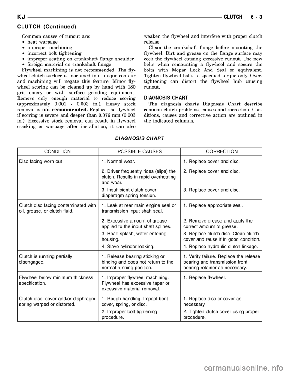
DIAGNOSIS CHART
The diagnosis charts Diagnosis Chart describe
common clutch problems, causes and correction. Con-
ditions, causes and corrective action are outlined in
the indicated columns.
DIAGNOSIS CHART
CONDITION POSSIBLE CAUSES CORRECTION
Disc facing worn out 1. Normal wear. 1. Replace cover and disc.
2. Driver frequently rides (slips) the
clutch. Results in rapid overheating
and wear.2. Replace cover and disc.
3. Insufficient clutch cover
diaphragm spring tension.3. Replace cover and disc.
Clutch disc facing contaminated with
oil, grease, or clutch fluid.1. Leak at rear main engine seal or
transmission input shaft seal.1. Replace appropriate seal.
2. Excessive amount of grease
applied to the input shaft splines.2. Remove grease and apply the
correct amount of grease.
3. Road splash, water entering
housing.3. Replace clutch disc. Clean clutch
cover and reuse if in good condition.
4. Slave cylinder leaking. 4. Replace hydraulic clutch linkage.
Clutch is running partially
disengaged.1. Release bearing sticking or
binding and does not return to the
normal running position.1. Verify failure. Replace the release
bearing and transmission front
bearing retainer as necessary.
Flywheel below minimum thickness
specification.1. Improper flywheel machining.
Flywheel has excessive taper or
excessive material removal.1. Replace flywheel.
Clutch disc, cover and/or diaphragm
spring warped or distorted.1. Rough handling. Impact bent
cover, spring, or disc.1. Replace disc or cover as
necessary.
2. Improper bolt tightening
procedure.2. Tighten clutch cover using proper
procedure.
KJCLUTCH 6 - 3
CLUTCH (Continued)
Page 209 of 1803
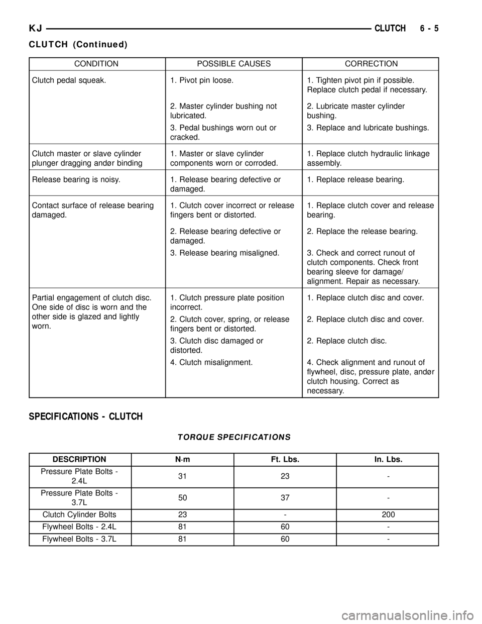
CONDITION POSSIBLE CAUSES CORRECTION
Clutch pedal squeak. 1. Pivot pin loose. 1. Tighten pivot pin if possible.
Replace clutch pedal if necessary.
2. Master cylinder bushing not
lubricated.2. Lubricate master cylinder
bushing.
3. Pedal bushings worn out or
cracked.3. Replace and lubricate bushings.
Clutch master or slave cylinder
plunger dragging andùr binding1. Master or slave cylinder
components worn or corroded.1. Replace clutch hydraulic linkage
assembly.
Release bearing is noisy. 1. Release bearing defective or
damaged.1. Replace release bearing.
Contact surface of release bearing
damaged.1. Clutch cover incorrect or release
fingers bent or distorted.1. Replace clutch cover and release
bearing.
2. Release bearing defective or
damaged.2. Replace the release bearing.
3. Release bearing misaligned. 3. Check and correct runout of
clutch components. Check front
bearing sleeve for damage/
alignment. Repair as necessary.
Partial engagement of clutch disc.
One side of disc is worn and the
other side is glazed and lightly
worn.1. Clutch pressure plate position
incorrect.1. Replace clutch disc and cover.
2. Clutch cover, spring, or release
fingers bent or distorted.2. Replace clutch disc and cover.
3. Clutch disc damaged or
distorted.2. Replace clutch disc.
4. Clutch misalignment. 4. Check alignment and runout of
flywheel, disc, pressure plate, andùr
clutch housing. Correct as
necessary.
SPECIFICATIONS - CLUTCH
TORQUE SPECIFICATIONS
DESCRIPTION N´m Ft. Lbs. In. Lbs.
Pressure Plate Bolts -
2.4L31 23 -
Pressure Plate Bolts -
3.7L50 37 -
Clutch Cylinder Bolts 23 - 200
Flywheel Bolts - 2.4L 81 60 -
Flywheel Bolts - 3.7L 81 60 -
KJCLUTCH 6 - 5
CLUTCH (Continued)