width JEEP LIBERTY 2002 KJ / 1.G Owner's Manual
[x] Cancel search | Manufacturer: JEEP, Model Year: 2002, Model line: LIBERTY, Model: JEEP LIBERTY 2002 KJ / 1.GPages: 1803, PDF Size: 62.3 MB
Page 1264 of 1803
FLEX PLATE
REMOVAL
(1) Remove the transmission.
(2) Remove the bolts and flexplate.
INSTALLATION
(1) Position the flexplate onto the crankshaft and
install the bolts hand tight.
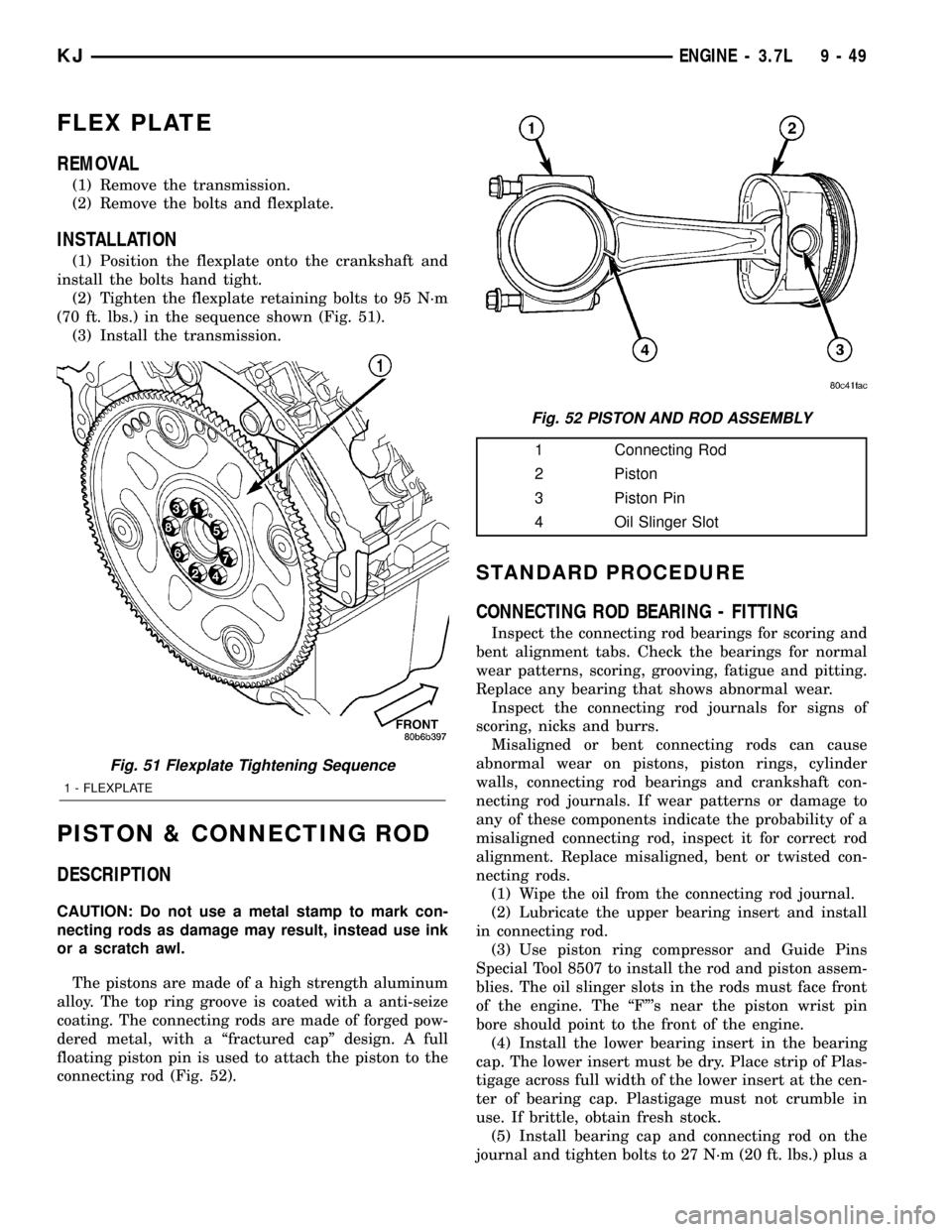
(2) Tighten the flexplate retaining bolts to 95 N´m
(70 ft. lbs.) in the sequence shown (Fig. 51).
(3) Install the transmission.
PISTON & CONNECTING ROD
DESCRIPTION
CAUTION: Do not use a metal stamp to mark con-
necting rods as damage may result, instead use ink
or a scratch awl.
The pistons are made of a high strength aluminum
alloy. The top ring groove is coated with a anti-seize
coating. The connecting rods are made of forged pow-
dered metal, with a ªfractured capº design. A full
floating piston pin is used to attach the piston to the
connecting rod (Fig. 52).
1 Connecting Rod
2 Piston
3 Piston Pin
4 Oil Slinger Slot
STANDARD PROCEDURE
CONNECTING ROD BEARING - FITTING
Inspect the connecting rod bearings for scoring and
bent alignment tabs. Check the bearings for normal
wear patterns, scoring, grooving, fatigue and pitting.
Replace any bearing that shows abnormal wear.
Inspect the connecting rod journals for signs of
scoring, nicks and burrs.
Misaligned or bent connecting rods can cause
abnormal wear on pistons, piston rings, cylinder
walls, connecting rod bearings and crankshaft con-
necting rod journals. If wear patterns or damage to
any of these components indicate the probability of a
misaligned connecting rod, inspect it for correct rod
alignment. Replace misaligned, bent or twisted con-
necting rods.
(1) Wipe the oil from the connecting rod journal.
(2) Lubricate the upper bearing insert and install
in connecting rod.
(3) Use piston ring compressor and Guide Pins
Special Tool 8507 to install the rod and piston assem-
blies. The oil slinger slots in the rods must face front
of the engine. The ªFº's near the piston wrist pin
bore should point to the front of the engine.
(4) Install the lower bearing insert in the bearing
cap. The lower insert must be dry. Place strip of Plas-
tigage across full width of the lower insert at the cen-
ter of bearing cap. Plastigage must not crumble in
use. If brittle, obtain fresh stock.
(5) Install bearing cap and connecting rod on the
journal and tighten bolts to 27 N´m (20 ft. lbs.) plus a
Fig. 51 Flexplate Tightening Sequence
1 - FLEXPLATE
Fig. 52 PISTON AND ROD ASSEMBLY
KJENGINE - 3.7L 9 - 49
Page 1265 of 1803
90É turn. DO NOT rotate crankshaft. Plastigage will
smear, resulting in inaccurate indication.
(6) Remove the bearing cap and determine amount
of bearing-to-journal clearance by measuring the
width of compressed Plastigage. Refer to Engine
Specifications for the proper clearance.Plastigage
should indicate the same clearance across the
entire width of the insert. If the clearance var-
ies, it may be caused by either a tapered jour-
nal, bent connecting rod or foreign material
trapped between the insert and cap or rod.
(7) If the correct clearance is indicated, replace-
ment of the bearing inserts is not necessary. Remove
the Plastigage from crankshaft journal and bearing
insert. Proceed with installation.
(8) If bearing-to-journal clearance exceeds the
specification, determin which services bearing set to
use the bearing sizes are as follows:
Bearing
MarkSIZE USED WITH
JOURNAL SIZE
.025 US.025 mm 57.871-57.879 mm
(.001 in.) (2.2783-2.2786 in.)
Std.STANDARD 57.896-57.904 mm
(2.2793-2.2810 in.)
.250 US.250 mm 57.646-57.654 mm
(.010 in.) (2.2695-2.2698 in.)
(9) Repeat the Plastigage measurement to verify
your bearing selection prior to final assembly.
(10) Once you have selected the proper insert,
install the insert and cap. Tighten the connecting rod
bolts to 27 N´m (20 ft. lbs.) plus a 90É turn.
Slide snug-fitting feeler gauge between the con-
necting rod and crankshaft journal flange. Refer to
Engine Specifications for the proper clearance.
Replace the connecting rod if the side clearance is
not within specification.
STANDARD PROCEDURE - PISTON FITTING
(1) To correctly select the proper size piston, a cyl-
inder bore gauge, capable of reading in 0.003 mm (
.0001 in.) INCREMENTS is required. If a bore gauge
is not available, do not use an inside micrometer.
(2) Measure the inside diameter of the cylinder
bore at a point 38.0 mm (1.5 inches) below top of
bore. Start perpendicular (across or at 90 degrees) to
the axis of the crankshaft at point A and then take
an additional bore reading 90 degrees to that at point
B (Fig. 54).
(3) The coated pistons will be serviced with the
piston pin and connecting rod pre-assembled.(4) The coating material is applied to the piston
after the final piston machining process. Measuring
the outside diameter of a coated piston will not pro-
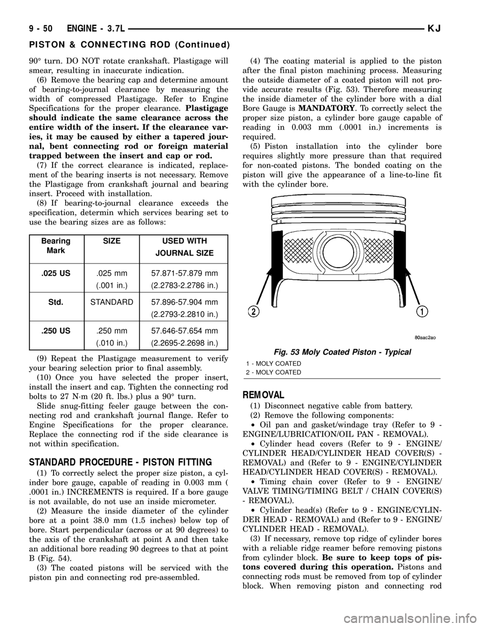
vide accurate results (Fig. 53). Therefore measuring
the inside diameter of the cylinder bore with a dial
Bore Gauge isMANDATORY. To correctly select the
proper size piston, a cylinder bore gauge capable of
reading in 0.003 mm (.0001 in.) increments is
required.
(5) Piston installation into the cylinder bore
requires slightly more pressure than that required
for non-coated pistons. The bonded coating on the
piston will give the appearance of a line-to-line fit
with the cylinder bore.
REMOVAL
(1) Disconnect negative cable from battery.
(2) Remove the following components:
²Oil pan and gasket/windage tray (Refer to 9 -
ENGINE/LUBRICATION/OIL PAN - REMOVAL).
²Cylinder head covers (Refer to 9 - ENGINE/
CYLINDER HEAD/CYLINDER HEAD COVER(S) -
REMOVAL) and (Refer to 9 - ENGINE/CYLINDER
HEAD/CYLINDER HEAD COVER(S) - REMOVAL).
²Timing chain cover (Refer to 9 - ENGINE/
VALVE TIMING/TIMING BELT / CHAIN COVER(S)
- REMOVAL).
²Cylinder head(s) (Refer to 9 - ENGINE/CYLIN-
DER HEAD - REMOVAL) and (Refer to 9 - ENGINE/
CYLINDER HEAD - REMOVAL).
(3) If necessary, remove top ridge of cylinder bores
with a reliable ridge reamer before removing pistons
from cylinder block.Be sure to keep tops of pis-
tons covered during this operation.Pistons and
connecting rods must be removed from top of cylinder
block. When removing piston and connecting rod
Fig. 53 Moly Coated Piston - Typical
1 - MOLY COATED
2 - MOLY COATED
9 - 50 ENGINE - 3.7LKJ
PISTON & CONNECTING ROD (Continued)
Page 1271 of 1803
CAUTION: The structural cover must be held tightly
against both the engine and the transmission bell
housing during tightening sequence. Failure to do
so may cause damage to the cover.
(4) Starting with the two rear cover-to-engine
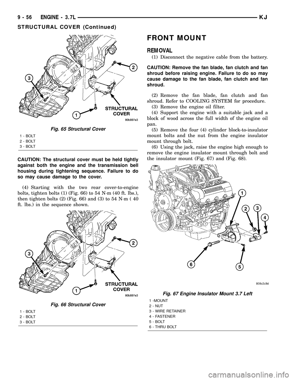
bolts, tighten bolts (1) (Fig. 66) to 54 N´m (40 ft. lbs.),
then tighten bolts (2) (Fig. 66) and (3) to 54 N´m ( 40
ft. lbs.) in the sequence shown.
FRONT MOUNT
REMOVAL
(1) Disconnect the negative cable from the battery.
CAUTION: Remove the fan blade, fan clutch and fan
shroud before raising engine. Failure to do so may
cause damage to the fan blade, fan clutch and fan
shroud.
(2) Remove the fan blade, fan clutch and fan
shroud. Refer to COOLING SYSTEM for procedure.
(3) Remove the engine oil filter.
(4) Support the engine with a suitable jack and a
block of wood across the full width of the engine oil
pan.
(5) Remove the four (4) cylinder block-to-insulator
mount bolts and the nut from the engine insulator
mount through bolt.
(6) Using the jack, raise the engine high enough to
remove the engine insulator mount through bolt and
the insulator mount (Fig. 67) and (Fig. 68).
Fig. 65 Structural Cover
1 - BOLT
2 - BOLT
3 - BOLT
Fig. 66 Structural Cover
1 - BOLT
2 - BOLT
3 - BOLT
Fig. 67 Engine Insulator Mount 3.7 Left
1 -MOUNT
2 - NUT
3 - WIRE RETAINER
4 - FASTENER
5 - BOLT
6 - THRU BOLT
9 - 56 ENGINE - 3.7LKJ
STRUCTURAL COVER (Continued)
Page 1306 of 1803
CONDITION POSSIBLE CAUSES CORRECTION
OIL CONSUMPTION OR SPARK
PLUGS FOULED1. PCV system malfunction. 1. Check system and repair as
necessary. (Refer to 25 -
EMISSIONS CONTROL/
EVAPORATIVE EMISSIONS/PCV
VALVE - DIAGNOSIS AND
TESTING)
2. Worn, scuffed or broken rings. 2. Hone cylinder bores. Install new
rings.
3. Carbon in oil ring slots. 3. Install new rings.
4. Rings fitted too tightly in grooves. 4. Remove rings and check
grooves. If groove is not proper
width, replace piston.
5. Worn valve guide(s). 5. Replace cylinder head assembly.
6. Valve stem seal(s) worn or
damaged.6. Replace seal(s).
STANDARD PROCEDURE
STANDARD PROCEDURE - ENGINE CORE AND
OIL GALLERY PLUGS
Using a blunt tool such as a drift and a hammer,
strike the bottom edge of the cup plug. With the cup
plug rotated, grasp firmly with pliers or other suit-
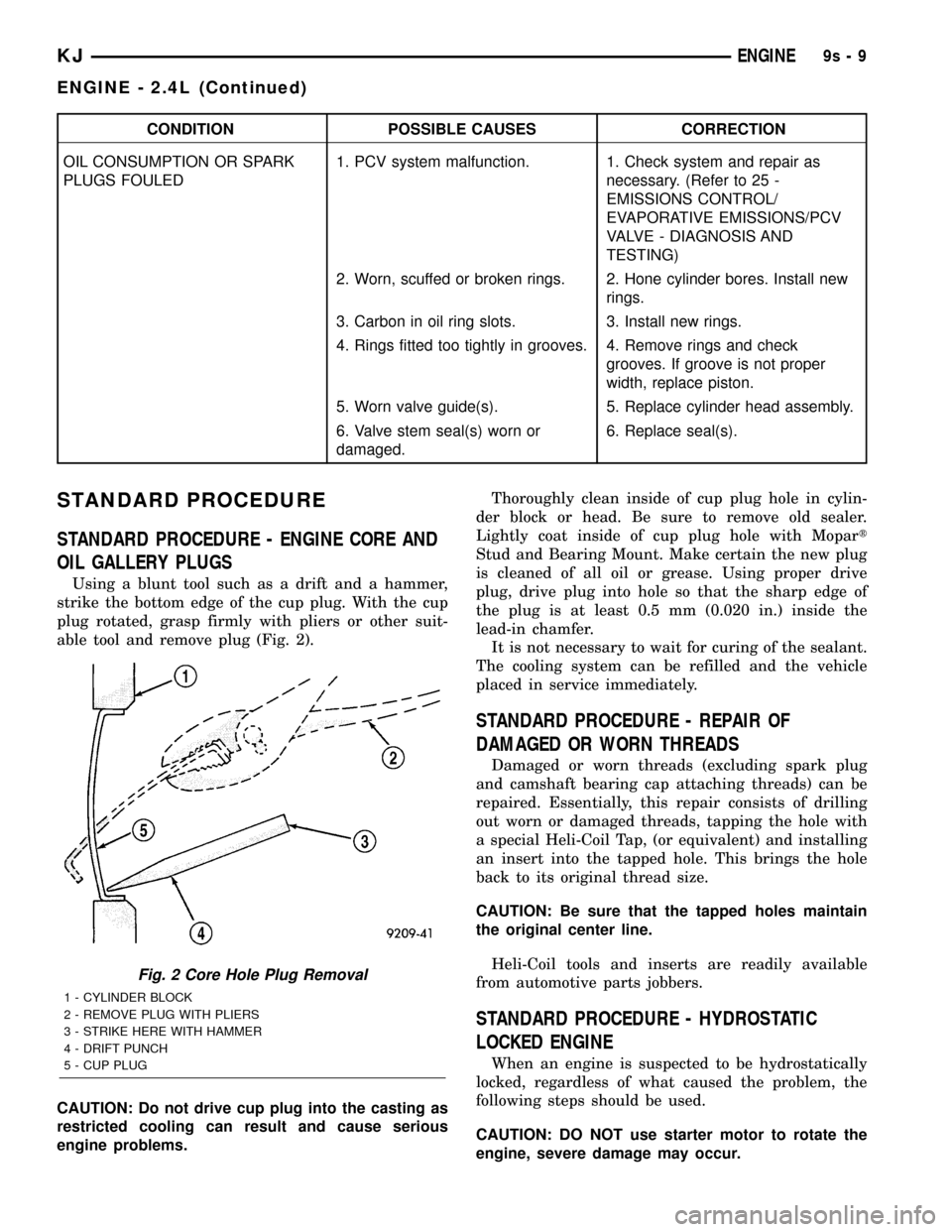
able tool and remove plug (Fig. 2).
CAUTION: Do not drive cup plug into the casting as
restricted cooling can result and cause serious
engine problems.Thoroughly clean inside of cup plug hole in cylin-
der block or head. Be sure to remove old sealer.
Lightly coat inside of cup plug hole with Mopart
Stud and Bearing Mount. Make certain the new plug
is cleaned of all oil or grease. Using proper drive
plug, drive plug into hole so that the sharp edge of
the plug is at least 0.5 mm (0.020 in.) inside the
lead-in chamfer.
It is not necessary to wait for curing of the sealant.
The cooling system can be refilled and the vehicle
placed in service immediately.
STANDARD PROCEDURE - REPAIR OF
DAMAGED OR WORN THREADS
Damaged or worn threads (excluding spark plug
and camshaft bearing cap attaching threads) can be
repaired. Essentially, this repair consists of drilling
out worn or damaged threads, tapping the hole with
a special Heli-Coil Tap, (or equivalent) and installing
an insert into the tapped hole. This brings the hole
back to its original thread size.
CAUTION: Be sure that the tapped holes maintain
the original center line.
Heli-Coil tools and inserts are readily available
from automotive parts jobbers.
STANDARD PROCEDURE - HYDROSTATIC
LOCKED ENGINE
When an engine is suspected to be hydrostatically
locked, regardless of what caused the problem, the
following steps should be used.
CAUTION: DO NOT use starter motor to rotate the
engine, severe damage may occur.
Fig. 2 Core Hole Plug Removal
1 - CYLINDER BLOCK
2 - REMOVE PLUG WITH PLIERS
3 - STRIKE HERE WITH HAMMER
4 - DRIFT PUNCH
5 - CUP PLUG
KJENGINE9s-9
ENGINE - 2.4L (Continued)
Page 1307 of 1803
(1) Inspect air cleaner, induction system and
intake manifold to insure system is dry and clear of
foreign material.
(2) Remove negative battery cable.
(3) Place a shop towel around the spark plugs
when removing them from the engine. This will catch
any fluid that may possibly be in the cylinder under
pressure.
(4) With all spark plugs removed, rotate engine
crankshaft using a breaker bar and socket.
(5) Identify the fluid in the cylinder(s) (i.e., cool-
ant, fuel, oil or other).
(6) Make sure all fluid has been removed from the
cylinders. Inspect engine for damage (i.e., connecting
rods, pistons, valves, etc.)
(7) Repair engine or components as necessary to
prevent this problem from re-occurring.
CAUTION: Squirt approximately one teaspoon of oil
into the cylinders, rotate engine to lubricate the cyl-
inder walls to prevent damage on restart.
(8) Install new spark plugs.
(9) Drain engine oil and remove oil filter.
(10) Install a new oil filter.
(11) Fill engine with specified amount of approved
oil.
(12) Connect negative battery cable.
(13) Start engine and check for any leaks.
STANDARD PROCEDURE - FORM-IN-PLACE
GASKETS AND SEALERS
There are numerous places where form-in-place
gaskets are used on the engine. Care must be taken
when applying form-in-place gaskets to assure
obtaining the desired results.Do not use form-in-
place gasket material unless specified.Bead size,
continuity, and location are of great importance. Too
thin a bead can result in leakage while too much can
result in spill-over which can break off and obstruct
fluid feed lines. A continuous bead of the proper
width is essential to obtain a leak-free gasket.
There are numerous types of form-in-place gasket
materials that are used in the engine area. Mopart
Engine RTV GEN II, MopartATF-RTV, and Mopart
Gasket Maker gasket materials, each have different
properties and can not be used in place of the other.
MOPARtENGINE RTV GEN IIis used to seal
components exposed to engine oil. This material is a
specially designed black silicone rubber RTV that
retains adhesion and sealing properties when
exposed to engine oil. Moisture in the air causes the
material to cure. This material is available in three
ounce tubes and has a shelf life of one year. After one
year this material will not properly cure. Alwaysinspect the package for the expiration date before
use.
MOPARtATF RTVis a specifically designed
black silicone rubber RTV that retains adhesion and
sealing properties to seal components exposed to
automatic transmission fluid, engine coolants, and
moisture. This material is available in three ounce
tubes and has a shelf life of one year. After one year
this material will not properly cure. Always inspect
the package for the expiration date before use.
MOPARtGASKET MAKERis an anaerobic type
gasket material. The material cures in the absence of
air when squeezed between two metallic surfaces. It
will not cure if left in the uncovered tube. The
anaerobic material is for use between two machined
surfaces. Do not use on flexible metal flanges.
MOPARtBED PLATE SEALANTis a unique
(green-in-color) anaerobic type gasket material that
is specially made to seal the area between the bed-
plate and cylinder block without disturbing the bear-
ing clearance or alignment of these components. The
material cures slowly in the absence of air when
torqued between two metallic surfaces, and will rap-
idly cure when heat is applied.
MOPARtGASKET SEALANTis a slow drying,
permanently soft sealer. This material is recom-
mended for sealing threaded fittings and gaskets
against leakage of oil and coolant. Can be used on
threaded and machined parts under all tempera-
tures. This material is used on engines with multi-
layer steel (MLS) cylinder head gaskets. This
material also will prevent corrosion. MopartGasket
Sealant is available in a 13 oz. aerosol can or 4oz./16
oz. can w/applicator.
SEALER APPLICATION
MopartGasket Maker material should be applied
sparingly 1 mm (0.040 in.) diameter or less of sealant
to one gasket surface. Be certain the material sur-
rounds each mounting hole. Excess material can eas-
ily be wiped off. Components should be torqued in
place within 15 minutes. The use of a locating dowel
is recommended during assembly to prevent smear-
ing material off the location.
MopartEngine RTV GEN II or ATF RTV gasket
material should be applied in a continuous bead
approximately 3 mm (0.120 in.) in diameter. All
mounting holes must be circled. For corner sealing, a
3.17 or 6.35 mm (1/8 or 1/4 in.) drop is placed in the
center of the gasket contact area. Uncured sealant
may be removed with a shop towel. Components
should be torqued in place while the sealant is still
wet to the touch (within 10 minutes). The usage of a
locating dowel is recommended during assembly to
prevent smearing material off the location.
9s - 10 ENGINEKJ
ENGINE - 2.4L (Continued)
Page 1308 of 1803
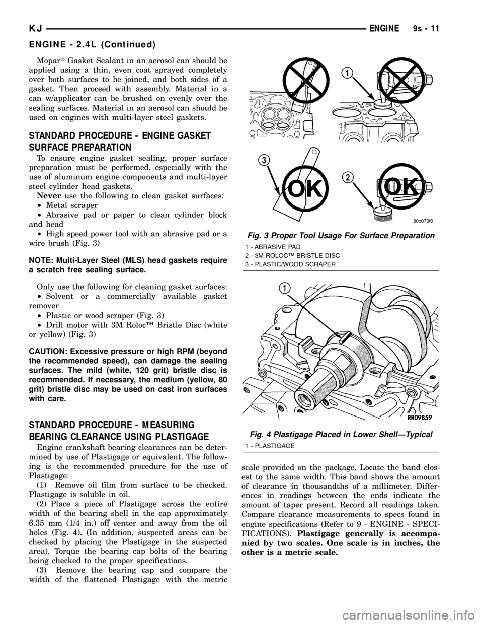
MopartGasket Sealant in an aerosol can should be
applied using a thin, even coat sprayed completely
over both surfaces to be joined, and both sides of a
gasket. Then proceed with assembly. Material in a
can w/applicator can be brushed on evenly over the
sealing surfaces. Material in an aerosol can should be
used on engines with multi-layer steel gaskets.
STANDARD PROCEDURE - ENGINE GASKET
SURFACE PREPARATION
To ensure engine gasket sealing, proper surface
preparation must be performed, especially with the
use of aluminum engine components and multi-layer
steel cylinder head gaskets.
Neveruse the following to clean gasket surfaces:
²Metal scraper
²Abrasive pad or paper to clean cylinder block
and head
²High speed power tool with an abrasive pad or a
wire brush (Fig. 3)
NOTE: Multi-Layer Steel (MLS) head gaskets require
a scratch free sealing surface.
Only use the following for cleaning gasket surfaces:
²Solvent or a commercially available gasket
remover
²Plastic or wood scraper (Fig. 3)
²Drill motor with 3M RolocŸ Bristle Disc (white
or yellow) (Fig. 3)
CAUTION: Excessive pressure or high RPM (beyond
the recommended speed), can damage the sealing
surfaces. The mild (white, 120 grit) bristle disc is
recommended. If necessary, the medium (yellow, 80
grit) bristle disc may be used on cast iron surfaces
with care.
STANDARD PROCEDURE - MEASURING
BEARING CLEARANCE USING PLASTIGAGE
Engine crankshaft bearing clearances can be deter-
mined by use of Plastigage or equivalent. The follow-
ing is the recommended procedure for the use of
Plastigage:
(1) Remove oil film from surface to be checked.
Plastigage is soluble in oil.
(2) Place a piece of Plastigage across the entire
width of the bearing shell in the cap approximately
6.35 mm (1/4 in.) off center and away from the oil
holes (Fig. 4). (In addition, suspected areas can be
checked by placing the Plastigage in the suspected
area). Torque the bearing cap bolts of the bearing
being checked to the proper specifications.
(3) Remove the bearing cap and compare the
width of the flattened Plastigage with the metricscale provided on the package. Locate the band clos-
est to the same width. This band shows the amount
of clearance in thousandths of a millimeter. Differ-
ences in readings between the ends indicate the
amount of taper present. Record all readings taken.
Compare clearance measurements to specs found in
engine specifications (Refer to 9 - ENGINE - SPECI-
FICATIONS).Plastigage generally is accompa-
nied by two scales. One scale is in inches, the
other is a metric scale.
Fig. 3 Proper Tool Usage For Surface Preparation
1 - ABRASIVE PAD
2 - 3M ROLOCŸ BRISTLE DISC
3 - PLASTIC/WOOD SCRAPER
Fig. 4 Plastigage Placed in Lower ShellÐTypical
1 - PLASTIGAGE
KJENGINE9s-11
ENGINE - 2.4L (Continued)
Page 1311 of 1803
DESCRIPTION SPECIFICATION
Piston Ring Groove
Depth No. 34.097±4.236 mm
(0.161±0.166 in.)
Piston Pins
Clearance in Piston 0.005±0.018 mm
(0.0002±0.0008 in.)
Clearance in Connecting
RodInterference
Diameter 21.998±22.003 mm
(0.8660±0.8662 in.)
End Play None
Length 72.75±73.25 mm
(2.864±2.883 in.)
Piston Rings
Ring GapÐTop
Compression Ring0.25±0.51 mm
(0.0098±0.020 in.)
Wear Limit 0.8 mm
(0.031 in.)
Ring GapÐ2nd
Compression Ring0.23±0.48 mm
(0.009±0.018 in.)
Wear Limit 0.8 mm
(0.031 in.)
Ring GapÐOil Control
Steel Rails0.25±0.64 mm
(0.0098±0.025 in.)
Wear Limit 1.00 mm
(0.039 in.)
Ring Side ClearanceÐ
Compression Rings0.030±0.080 mm
(0.0011±0.0031 in.)
Wear Limit 0.10 mm
(0.004 in.)
Ring Side ClearanceÐOil
Ring Pack0.012±0.178 mm
(0.0004±0.0070 in.)
Ring WidthÐ
Compression Rings1.47±1.50 mm
(0.057±0.059 in.)
Ring WidthÐOil Ring
Pack2.72±2.88 mm
(0.107±0.1133 in.)
Connecting Rod
Bearing Clearance 0.025±0.071 mm
(0.0009±0.0027 in.)
Wear Limit 0.075 mm
(0.003 in.)
Bore DiameterÐPiston
Pin20.96±20.98 mm
(0.8252±0.8260 in.)DESCRIPTION SPECIFICATION
Bore DiameterÐ
Crankshaft End53.007±52.993 mm
(2.0868±2.0863 in.)
Side Clearance 0.13±0.38 mm
(0.005±0.015 in.)
Wear Limit 0.40 mm
(0.016 in.)
WeightÐTotal (Less
Bearing)565.8 grams
(19.96 oz.)
Crankshaft
Connecting Rod Journal
Diameter49.984±50.000 mm
(1.968±1.9685 in.)
Main Bearing Journal
Diameter59.992±60.008 mm
(2.362±2.3625 in.)
Journal Out-of-Round
(Max.)0.0035 mm
(0.0003 in.)
Journal Taper (Max.) 0.007 mm
(0.0001 in.)
End Play 0.09±0.24 mm
(0.0035±0.0094 in.)
Wear Limit 0.38 mm
(0.015 in.)
Main Bearing Diametrical
Clearance0.018±0.062 mm
(0.0007±0.0024 in.)
Hydraulic Lash Adjuster
Body Diameter 15.901±15.913 mm
(0.626±0.6264 in.)
Plunger Travel Minimum
(Dry)3.0 mm
(0.118 in.)
Cylinder Head Camshaft Bearing Bore Diameter
Journals No.1±6 26.020±26.041 mm
(1.024±1.025 in.)
Camshaft
Journal Diameter No. 1±6 25.951±25.970 mm
(1.021±1.022 in.)
Bearing ClearanceÐ
Diametrical0.069±0.071 mm
(0.0027±0.003 in.)
End Play 0.05±0.17 mm
(0.0019±0.0066 in.)
Lift (Zero Lash)
Intake 8.25 mm
(0.324 in.)
9s - 14 ENGINEKJ
ENGINE - 2.4L (Continued)
Page 1312 of 1803
DESCRIPTION SPECIFICATION
Exhaust 6.60 mm
(0.259 t>
Intake Valve Timing*
Closes (ABDC) 51É
Opens (BTDC) 1É
Duration 232É
Exhaust Valve Timing*
Closes (ATDC) 7É
Opens (BBDC) 47É
Duration 234É
Valve Overlap 8É
*All readings in crankshaft degrees. Timing points @
4É from top of Ramps.
Cylinder Head
Material Cast Aluminum
Gasket Thickness
(Compressed)0.71 mm
(0.028 in.)
Valve Seat
Angle 44.5±45É
Seat DiameterÐIntake 34.37±34.63 mm
(1.353±1.363 in.)
Seat DiameterÐExhaust 27.06±27.32 mm
(1.065±1.075 in.)
Runout (Max.) 0.05 mm
(0.002 in.)
Valve Seat WidthÐIntake
and Exhaust0.9±1.3 mm
(0.035±0.051 in.)
Service LimitÐIntake 2.0 mm
(0.079 in.)
Service LimitÐExhaust 2.5 mm
(0.098 in.)
Valve Guide
Diameter I.D. 5.975±6.000 mm
(0.235±0.236 in.)
Guide Bore Diameter 11.0±11.02 mm
(0.4330±0.4338 in.)
Guide Height (spring seat
to guide tip)13.25±13.75 mm
(0.521±0.541 in.)
Valves
Face AngleÐIntake and
Exhaust44.5Ð45ÉDESCRIPTION SPECIFICATION
Head DiameterÐIntake 34.67±34.93 mm
1.364±1.375 in.)
Head DiameterÐExhaust 28.32±28.52 mm
(1.114±1.122 in.)
Valve Length (Overall)
ÐIntake 112.76±113.32 mm
(4.439±4.461 in.)
ÐExhaust 110.89±111.69 mm
(4.365±4.397 in.)
Valve Stem Diameter
ÐIntake 5.934±5.952 mm
(0.2337±0.2344 in.)
ÐExhaust 5.906±5.924 mm
(0.2326±0.2333 in.)
Valve Margin
Intake 1.2±1.7 mm
(0.047±0.066 in.)
Service Limit 0.95 mm
(1/32 in.)
Exhaust 0.985±1.315 mm
(0.038±0.051 in.)
Service Limit 1.05 mm
(3/64 in.)
Valve Stem Tip
Intake 48.04 mm
(1.891 in.)
Exhaust 47.99 mm
(1.889 in.)
Valve Stem to Guide Clearance
Intake 0.048±0.066 mm
(0.0018±0.0025 in.)
Max. Allowable 0.076 mm
(0.003 in.)
Service Limit 0.25 mm
(0.010 in.)
Exhaust 0.0736±0.094 mm
(0.0029±0.0037 in.)
Max. Allowable 0.101 mm
(0.004 in.)
Service Limit 0.25 mm
(0.010 in.)
KJENGINE9s-15
ENGINE - 2.4L (Continued)
Page 1415 of 1803
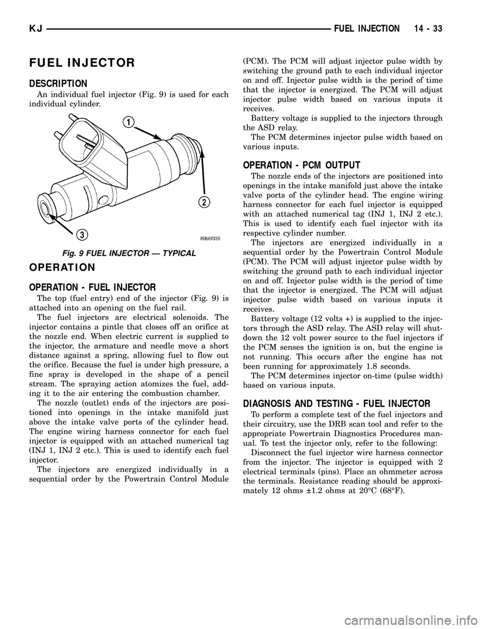
FUEL INJECTOR
DESCRIPTION
An individual fuel injector (Fig. 9) is used for each
individual cylinder.
OPERATION
OPERATION - FUEL INJECTOR
The top (fuel entry) end of the injector (Fig. 9) is
attached into an opening on the fuel rail.
The fuel injectors are electrical solenoids. The
injector contains a pintle that closes off an orifice at
the nozzle end. When electric current is supplied to
the injector, the armature and needle move a short
distance against a spring, allowing fuel to flow out
the orifice. Because the fuel is under high pressure, a
fine spray is developed in the shape of a pencil
stream. The spraying action atomizes the fuel, add-
ing it to the air entering the combustion chamber.
The nozzle (outlet) ends of the injectors are posi-
tioned into openings in the intake manifold just
above the intake valve ports of the cylinder head.
The engine wiring harness connector for each fuel
injector is equipped with an attached numerical tag
(INJ 1, INJ 2 etc.). This is used to identify each fuel
injector.
The injectors are energized individually in a
sequential order by the Powertrain Control Module(PCM). The PCM will adjust injector pulse width by
switching the ground path to each individual injector
on and off. Injector pulse width is the period of time
that the injector is energized. The PCM will adjust
injector pulse width based on various inputs it
receives.
Battery voltage is supplied to the injectors through
the ASD relay.
The PCM determines injector pulse width based on
various inputs.
OPERATION - PCM OUTPUT
The nozzle ends of the injectors are positioned into
openings in the intake manifold just above the intake
valve ports of the cylinder head. The engine wiring
harness connector for each fuel injector is equipped
with an attached numerical tag (INJ 1, INJ 2 etc.).
This is used to identify each fuel injector with its
respective cylinder number.
The injectors are energized individually in a
sequential order by the Powertrain Control Module
(PCM). The PCM will adjust injector pulse width by
switching the ground path to each individual injector
on and off. Injector pulse width is the period of time
that the injector is energized. The PCM will adjust
injector pulse width based on various inputs it
receives.
Battery voltage (12 volts +) is supplied to the injec-
tors through the ASD relay. The ASD relay will shut-
down the 12 volt power source to the fuel injectors if
the PCM senses the ignition is on, but the engine is
not running. This occurs after the engine has not
been running for approximately 1.8 seconds.
The PCM determines injector on-time (pulse width)
based on various inputs.
DIAGNOSIS AND TESTING - FUEL INJECTOR
To perform a complete test of the fuel injectors and
their circuitry, use the DRB scan tool and refer to the
appropriate Powertrain Diagnostics Procedures man-
ual. To test the injector only, refer to the following:
Disconnect the fuel injector wire harness connector
from the injector. The injector is equipped with 2
electrical terminals (pins). Place an ohmmeter across
the terminals. Resistance reading should be approxi-
mately 12 ohms 1.2 ohms at 20ÉC (68ÉF).
Fig. 9 FUEL INJECTOR Ð TYPICAL
KJFUEL INJECTION 14 - 33
Page 1418 of 1803

REMOVAL
2.4L
The Idle Air Control (IAC) motor is located on the
rear side of the throttle body (Fig. 12).
(1) Disconnect electrical connector from IAC motor.
(2) Remove two mounting bolts (screws).
(3) Remove IAC motor from throttle body.
3.7L
The Idle Air Control (IAC) motor is located on the
side of the throttle body (Fig. 13).
(1) Disconnect electrical connector from IAC motor.
(2) Remove two mounting bolts (screws).
(3) Remove IAC motor from throttle body.
INSTALLATION
2.4L
The Idle Air Control (IAC) motor is located on the
rear side of the throttle body.
(1) Install IAC motor to throttle body.
(2) Install and tighten two mounting bolts (screws)
to 7 N´m (60 in. lbs.) torque.
(3) Install electrical connector.
3.7L
The Idle Air Control (IAC) motor is located on the
side of the throttle body (Fig. 13).
(1) Install IAC motor to throttle body.(2) Install and tighten two mounting bolts (screws)
to 7 N´m (60 in. lbs.) torque.
(3) Install electrical connector.
INTAKE AIR TEMPERATURE
SENSOR
DESCRIPTION
The 2±wire Intake Manifold Air Temperature (IAT)
sensor is installed in the intake manifold with the
sensor element extending into the air stream.
The IAT sensor is a two-wire Negative Thermal
Coefficient (NTC) sensor. Meaning, as intake mani-
fold temperature increases, resistance (voltage) in the
sensor decreases. As temperature decreases, resis-
tance (voltage) in the sensor increases.
OPERATION
The IAT sensor provides an input voltage to the
Powertrain Control Module (PCM) indicating the
density of the air entering the intake manifold based
upon intake manifold temperature. At key-on, a
5±volt power circuit is supplied to the sensor from
the PCM. The sensor is grounded at the PCM
through a low-noise, sensor-return circuit.
The PCM uses this input to calculate the following:
²Injector pulse-width
²Adjustment of spark timing (to help prevent
spark knock with high intake manifold air-charge
temperatures)
Fig. 12 TPS/IAC MOTOR - 2.4L
1 - THROTTLE POSITION SENSOR (TPS)
2 - MOUNTING SCREWS
3 - IDLE AIR CONTROL MOTOR (IAC)
4 - MOUNTING SCREWS
Fig. 13 TPS/IAC MOTOR - 3.7L
1 - THROTTLE POSITION SENSOR (TPS)
2 - MOUNTING SCREWS
3 - IDLE AIR CONTROL MOTOR (IAC)
4 - MOUNTING SCREWS
14 - 36 FUEL INJECTIONKJ
IDLE AIR CONTROL MOTOR (Continued)