check engine light JEEP LIBERTY 2002 KJ / 1.G Owner's Guide
[x] Cancel search | Manufacturer: JEEP, Model Year: 2002, Model line: LIBERTY, Model: JEEP LIBERTY 2002 KJ / 1.GPages: 1803, PDF Size: 62.3 MB
Page 689 of 1803

continuity. If OK, go to Step 6. If not OK, repair the
open ground circuit(s) to ground (G202) as required.
(6) Reconnect the battery negative cable. Check for
battery voltage at the fused B(+) circuit cavity of the
instrument panel wire harness connector for the
SKIM. If OK, go to Step 7. If not OK, repair the open
fused B(+) circuit between the SKIM and the JB as
required.
(7) Turn the ignition switch to the On position.
Check for battery voltage at the fused ignition switch
output (run-start) circuit cavity of the instrument
panel wire harness connector for the SKIM. If OK,
use a DRBIIItscan tool to complete the diagnosis of
the SKIS. Refer to the appropriate diagnostic infor-
mation. If not OK, repair the open fused ignition
switch output (run-start) circuit between the SKIM
and the JB as required.
SKIS INDICATOR FLASHES UPON IGNITION ªONº OR
LIGHTS SOLID FOLLOWING BULB TEST
A SKIS indicator that flashes following the ignition
switch being turned to the On position indicates that
an invalid key has been detected, or that a key-re-
lated fault has been set. A SKIS indicator that lights
solid following a successful bulb test indicates that
the SKIM has detected a system malfunction or that
the SKIS is inoperative. In either case, fault informa-
tion will be stored in the SKIM memory. For retrieval
of this fault information and further diagnosis of the
SKIS, the PCI data bus, the SKIM electronic mes-
sage outputs to the instrument cluster that control
the SKIS indicator and chime, or the electronic mes-
sage inputs and outputs between the SKIM and the
Powertrain Control Module (PCM) that control
engine operation, a DRBIIItscan tool is required.
Refer to the appropriate diagnostic information. Fol-
lowing are preliminary troubleshooting guidelines to
be followed during diagnosis using a DRBIIItscan
tool:
(1) Using the DRBIIItscan tool, read and record
the faults as they exist in the SKIM when you first
begin your diagnosis of the vehicle. It is important to
document these faults because the SKIM does not
differentiate between historical faults (those that
have occurred in the past) and active faults (those
that are currently present). If this problem turns out
to be an intermittent condition, this information may
become invaluable to your diagnosis.
(2) Using the DRBIIItscan tool, erase all of the
faults from the SKIM.
(3) Cycle the ignition switch to the Off position,
then back to the On position.
(4) Using the DRBIIItscan tool, read any faults
that are now present in the SKIM. These are the
active faults.(5) Using this active fault information, refer to the
proper procedure in the appropriate diagnostic infor-
mation for the specific additional diagnostic steps.
STANDARD PROCEDURE
STANDARD PROCEDURE - SKIS
INITIALIZATION
The Sentry Key Immobilizer System (SKIS) must
be initialized following a Sentry Key Immobilizer
Module (SKIM) replacement. SKIS initialization
requires the use of a DRBIIItscan tool. Initialization
will also require that you have access to the unique
four-digit PIN code that was assigned to the original
SKIM. The PIN codemustbe used to enter the
Secured Access Mode in the SKIM. This PIN number
may be obtained from the vehicle owner, from the
original vehicle invoice, or from the DaimlerChrysler
Customer Center. (Refer to 8 - ELECTRICAL/ELEC-
TRONIC CONTROL MODULES - STANDARD PRO-
CEDURE - PCM/SKIM PROGRAMMING).
NOTE: If a Powertrain Control Module (PCM) is
replaced on a vehicle equipped with the Sentry Key
Immobilizer System (SKIS), the unique Secret Key
data must be transferred from the Sentry Key
Immobilizer Module (SKIM) to the new PCM using
the PCM replacement procedure. This procedure
also requires the use of a DRBIIITscan tool and the
unique four-digit PIN code to enter the Secured
Access Mode in the SKIM. Refer to the appropriate
diagnostic information for the proper PCM replace-
ment procedures.
STANDARD PROCEDURE - SENTRY KEY
TRANSPONDER PROGRAMMING
All Sentry Keys included with the vehicle are pre-
programmed to work with the Sentry Key Immobi-
lizer System (SKIS) when it is shipped from the
factory. The Sentry Key Immobilizer Module (SKIM)
can be programmed to recognize up to a total of eight
Sentry Keys. When programming a blank Sentry Key
transponder, the key must first be cut to match the
ignition switch lock cylinder in the vehicle for which
it will be used. Once the additional or new key has
been cut, the SKIM must be programmed to recog-
nize it as a valid key. There are two possible methods
to program the SKIM to recognize a new or addi-
tional valid key, the Secured Access Method and the
Customer Learn Method. Following are the details of
these two programming methods.
8Q - 8 VEHICLE THEFT SECURITYKJ
VEHICLE THEFT SECURITY (Continued)
Page 704 of 1803
An electrically operated intermittent front wiper
and washer system is standard factory-installed
safety equipment on this model (Fig. 1). The front
wiper and washer system includes the following
major components, which are described in further
detail elsewhere in this service information:
²Body Control Module- The Body Control
Module (BCM) is located on the Junction Block (JB)
under the driver side outboard end of the instrument
panel. (Refer to 8 - ELECTRICAL/ELECTRONIC
CONTROL MODULES/BODY CONTROL MODULE
- DESCRIPTION).
²Front Check Valve- The front washer system
check valve is integral to the wye fitting located in
the washer plumbing between the cowl plenum
washer hose and the front washer nozzles, and is
concealed beneath the cowl plenum cover/grille panel
at the base of the windshield.
²Front Washer Nozzle- Two fluidic front
washer nozzles are secured with integral snap fea-
tures to dedicated openings in the cowl plenum cover/
grille panel located near the base of the windshield.
²Front Washer Plumbing- The plumbing for
the front washer system consists of rubber hoses and
molded plastic fittings. The plumbing is routed along
the right side of the engine compartment from the
washer reservoir, and through the dash panel into
the cowl plenum to the front washer nozzle fittings
beneath the cowl plenum cover/grille panel.
²Front Wiper Arm- The two front wiper arms
are secured with nuts to the threaded studs on the
ends of the two wiper pivot shafts, which extend
through the cowl plenum cover/grille panel located
near the base of the windshield.
²Front Wiper Blade- The two front wiper
blades are secured to the two front wiper arms with
an integral latch, and are parked on the glass near
the bottom of the windshield when the front wiper
system is not in operation.
²Front Wiper Module- The front wiper pivot
shafts are the only visible components of the front
wiper module. The remainder of the module is con-
cealed within the cowl plenum area beneath the cowl
plenum cover/grille panel. The front wiper module
includes the wiper module bracket, four rubber-iso-
lated wiper module mounts, the front wiper motor,
the wiper motor crank arm, the two wiper drive
links, and the two front wiper pivots.
²Multi-Function Switch- The multi-function
switch is located on the top of the steering column,
just below the steering wheel. The multi-function
switch includes a left (lighting) control stalk and a
right (wiper) control stalk. The right control stalk is
dedicated to providing all of the driver controls for
both the front and rear wiper systems. (Refer to 8 -ELECTRICAL/LAMPS/LIGHTING - EXTERIOR/
MULTI-FUNCTION SWITCH - DESCRIPTION).
²Washer Fluid Level Switch- The washer fluid
level switch is located in a dedicated hole near the
center of the rearward facing surface of the washer
reservoir, behind the right front wheel house splash
shield.
²Washer Pump/Motor- The reversible electric
washer pump/motor unit is located in a dedicated
hole on the lower outboard side of the washer reser-
voir, behind the right front wheel house splash
shield. This single reversible washer pump/motor
provides washer fluid to either the front or rear
washer system plumbing, depending upon the direc-
tion of the pump motor rotation.
²Washer Reservoir- The washer reservoir is
concealed behind the right front wheel house splash
shield ahead of the right front wheel. The washer
reservoir filler neck is the only visible portion of the
reservoir, and it is accessed from the right front cor-
ner of the engine compartment.
²Wiper High-Low Relay- The wiper high-low
relay is an International Standards Organization
(ISO) micro relay located in the Power Distribution
Center (PDC) in the engine compartment near the
battery.
²Wiper On-Off Relay- The wiper on-off relay is
an International Standards Organization (ISO) micro
relay located in the Power Distribution Center (PDC)
in the engine compartment near the battery.
Hard wired circuitry connects the front wiper and
washer system components to the electrical system of
the vehicle. These hard wired circuits are integral to
several wire harnesses, which are routed throughout
the vehicle and retained by many different methods.
These circuits may be connected to each other, to the
vehicle electrical system and to the front wiper and
washer system components through the use of a com-
bination of soldered splices, splice block connectors,
and many different types of wire harness terminal
connectors and insulators. Refer to the appropriate
wiring information. The wiring information includes
wiring diagrams, proper wire and connector repair
procedures, further details on wire harness routing
and retention, as well as pin-out and location views
for the various wire harness connectors, splices and
grounds.
OPERATING MODES The components of the front
wiper and washer system are designed to work in
concert to provide the following operating modes:
²Continuous Wipe Mode- The control knob on
the right (wiper) control stalk of the multi-function
switch has two continuous wipe positions, Low and
High. When selected, these switch positions will
cause the two-speed front wiper motor to operate in a
continuous low or high speed cycle.
KJFRONT WIPERS/WASHERS 8R - 3
FRONT WIPERS/WASHERS (Continued)
Page 728 of 1803
REAR WIPERS/WASHERS
TABLE OF CONTENTS
page page
REAR WIPERS/WASHERS
DESCRIPTION.........................27
OPERATION...........................29
DIAGNOSIS AND TESTING - REAR WIPER &
WASHER SYSTEM....................30
CLEANING - REAR WIPER & WASHER
SYSTEM............................32
INSPECTION - REAR WIPER & WASHER
SYSTEM............................33
REAR CHECK VALVE
DESCRIPTION.........................34
OPERATION...........................34
REMOVAL.............................34
INSTALLATION.........................35
REAR WASHER HOSES/TUBES
DESCRIPTION.........................35
OPERATION...........................36
REAR WASHER NOZZLE
DESCRIPTION.........................36
OPERATION...........................36
REMOVAL.............................36
INSTALLATION.........................37REAR WIPER ARM
DESCRIPTION.........................37
OPERATION...........................38
REMOVAL.............................38
INSTALLATION.........................38
REAR WIPER BLADE
DESCRIPTION.........................39
OPERATION...........................39
REMOVAL.............................40
INSTALLATION.........................40
REAR WIPER MOTOR
DESCRIPTION.........................41
OPERATION...........................41
REMOVAL.............................42
INSTALLATION.........................42
REAR WIPER/WASHER SWITCH
DESCRIPTION.........................43
OPERATION...........................43
WIPER ARM PARK RAMP
REMOVAL.............................43
INSTALLATION.........................43
REAR WIPERS/WASHERS
DESCRIPTION
An electrically operated fixed interval intermittent
rear wiper and washer system is standard factory-in-
stalled equipment on this model (Fig. 1). The rear
wiper and washer system includes the following
major components, which are described in further
detail elsewhere in this service information:
²Multi-Function Switch- The multi-function
switch is located on the top of the steering column,
just below the steering wheel. The multi-function
switch includes a left (lighting) control stalk and a
right (wiper) control stalk. The right control stalk is
dedicated to providing all of the driver controls for
both the front and rear wiper systems. (Refer to 8 -
ELECTRICAL/LAMPS/LIGHTING - EXTERIOR/
MULTI-FUNCTION SWITCH - DESCRIPTION).
²Rear Check Valve- The rear washer system
check valve is located in the washer plumbing
between the rear roof header and the roof outer
panel near the rear washer nozzle.
²Rear Washer Nozzle- The rear washer nozzle
is secured by a snap fit into a mounting hole in the
roof outer panel above the rear flip-up glass opening.²Rear Washer Plumbing- The plumbing for
the rear washer system consists of rubber hoses and
molded plastic fittings. The plumbing is routed along
the right side of the engine compartment from the
washer reservoir, through the dash into the passen-
ger compartment, up the right cowl side and A-pillar
to the headliner, and above the headliner to the rear
washer nozzle fitting within the rear roof header.
²Rear Wiper Arm- The single rear wiper arm is
secured by a nut directly to the rear wiper motor out-
put shaft, which extends through the center of the
tailgate outer panel near the base of the rear flip-up
glass.
²Rear Wiper Arm Park Ramp- The molded
rubber rear wiper arm park ramp is secured with a
screw to the tailgate outer panel to the right of the
rear wiper motor output shaft bezel. When the rear
wiper system is not in operation, the rear wiper arm
is parked off of the rear flip-up glass on this ramp so
that it will not interfere with or be damaged by the
flip-up glass operation.
²Rear Wiper Blade- The single rear wiper
blade is secured to the rear wiper arm with an inte-
gral latch, and is parked off of the rear flip-up glass
when the rear wiper system is not in operation.
KJREAR WIPERS/WASHERS 8R - 27
Page 736 of 1803
(5) Remove the rear check valve and rear washer
nozzle hose as a unit through the CHMSL mounting
hole.
(6) Disconnect the rear washer nozzle hose from
the barbed nipple of the rear check valve.
INSTALLATION
(1) Reconnect the rear washer nozzle hose to the
barbed nipple of the rear check valve. Be certain that
the flow direction arrow molded into the rear check
valve body is oriented towards the rear washer noz-
zle hose.
WARNING: THE EDGES OF THE SHEET METAL
AROUND THE CENTER HIGH MOUNTED STOP
LAMP MOUNTING HOLE IN THE ROOF PANEL.
TAKE THE PROPER PRECAUTIONS TO AVOID PER-
SONAL INJURY.
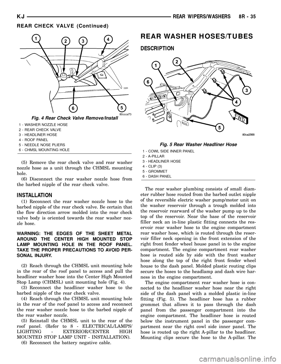
(2) Reach through the CHMSL unit mounting hole
in the rear of the roof panel to access and pull the
headliner washer hose into the Center High Mounted
Stop Lamp (CHMSL) unit mounting hole (Fig. 4).
(3) Reconnect the headliner washer hose to the
barbed nipple of the rear check valve.
(4) Reach through the CHMSL unit mounting hole
in the rear of the roof panel to access and reconnect
the rear washer nozzle hose to the barbed nipple of
the rear washer nozzle.
(5) Reinstall the CHMSL unit to the rear of the
roof panel. (Refer to 8 - ELECTRICAL/LAMPS/
LIGHTING - EXTERIOR/CENTER HIGH
MOUNTED STOP LAMP UNIT - INSTALLATION).
(6) Reconnect the battery negative cable.
REAR WASHER HOSES/TUBES
DESCRIPTION
The rear washer plumbing consists of small diam-
eter rubber hose routed from the barbed outlet nipple
of the reversible electric washer pump/motor unit on
the washer reservoir through a trough molded into
the reservoir rearward of the washer pump up to the
top of the reservoir. Near the base of the reservoir
filler neck an in-line plastic fitting connects the res-
ervoir rear washer hose to the engine compartment
rear washer hose, which is routed through the reser-
voir filler neck opening in the front extension of the
right front fender wheel house panel in to the engine
compartment. The engine compartment rear washer
hose is routed side by side with the front washer
hose along the top of the right front fender wheel
house to the dash panel. Molded plastic routing clips
secure the hoses to the headlamp and dash wire har-
ness in the engine compartment.
The engine compartment rear washer hose is con-
nected to the headliner washer hose near the right
side of the dash panel with a molded plastic in-line
fitting (Fig. 5). The headliner hose has a rubber
grommet that allows it to pass through the dash
panel from the passenger compartment into the
engine compartment. The headliner hose is routed
below the instrument panel in the passenger com-
partment near the right cowl side inner panel. The
hose is routed up the right A-pillar to the headliner.
Mounting clips secure the hose to the A-pillar. The
Fig. 4 Rear Check Valve Remove/Install
1 - WASHER NOZZLE HOSE
2 - REAR CHECK VALVE
3 - HEADLINER HOSE
4 - ROOF PANEL
5 - NEEDLE NOSE PLIERS
6 - CHMSL MOUNTING HOLE
Fig. 5 Rear Washer Headliner Hose
1 - COWL SIDE INNER PANEL
2 - A-PILLAR
3 - HEADLINER HOSE
4 - CLIP (3)
5 - GROMMET
6 - DASH PANEL
KJREAR WIPERS/WASHERS 8R - 35
REAR CHECK VALVE (Continued)
Page 753 of 1803
CIRCUIT FUNCTION
U OPEN
V SPEED CONTROL, WIPER/
WASHER
W OPEN
X AUDIO SYSTEMS
Y OPEN
Z GROUNDS
DESCRIPTION - SECTION IDENTIFICATION AND
INFORMATION
The wiring diagrams are grouped into individual
sections. If a component is most likely found in a par-
ticular group, it will be shown complete (all wires,
connectors, and pins) within that group. For exam-
ple, the Auto Shutdown Relay is most likely to be
found in Group 30, so it is shown there complete. It
can, however, be shown partially in another group if
it contains some associated wiring.
Splice diagrams in Section 8W-70 show the entire
splice and provide references to other sections the
splices serves. Section 8W-70 only contains splice dia-
grams that are not shown in their entirety some-
where else in the wiring diagrams.
Section 8W-80 shows each connector and the cir-
cuits involved with that connector. The connectors
are identified using the name/number on the dia-
gram pages.
WIRING SECTION CHART
GROUP TOPIC
8Wa-01 thru
8W-09General information and Diagram
Overview
8Wa-10 thru
8W-19Main Sources of Power and
Vehicle Grounding
8Wa-20 thru
8W-29Starting and Charging
8Wa-30 thru
8W-39Powertrain/Drivetrain Systems
8Wa-40 thru
8W-49Body Electrical items and A/C
8Wa-50 thru
8W-59Exterior Lighting, Wipers and
Trailer Tow
8Wa-60 thru
8W-69Power Accessories
8Wa-70 Splice Information
8Wa-80 Connector Pin Outs
8Wa-91 Connector, Ground and Splice
Locations
DESCRIPTION - CONNECTOR, GROUND AND
SPLICE INFORMATION
CAUTION: Not all connectors are serviced. Some
connectors are serviced only with a harness. A typ-
ical example might be the Supplemental Restraint
System connectors. Always check parts availability
before attempting a repair.
IDENTIFICATION
In-line connectors are identified by a number, as
follows:
²In-line connectors located in the engine compart-
ment are C100 series numbers
²In-line connectors located in the Instrument
Panel area are C200 series numbers.
²In-line connectors located in the body are C300
series numbers.
²Jumper harness connectors are C400 series
numbers.
²Grounds and ground connectors are identified
with a ªGº and follow the same series numbering as
the in-line connectors.
²Splices are identified with an ªSº and follow the
same series numbering as the in-line connectors.
²Component connectors are identified by the com-
ponent name instead of a number. Multiple connec-
tors on a component use a C1, C2, etc. identifier.
LOCATIONS
Section 8W-91 contains connector/ground/splice
location illustrations. The illustrations contain the
connector name (or number)/ground number/splice
number and component identification. Connector/
ground/splice location charts in section 8W-91 refer-
ence the figure numbers of the illustrations.
The abbreviation T/O is used in the component
location section to indicate a point in which the wir-
ing harness branches out to a component. The abbre-
viation N/S means Not Shown in the illustrations
WARNINGS - GENERAL
WARNINGSprovide information to prevent per-
sonal injury and vehicle damage. Below is a list of
general warnings that should be followed any time a
vehicle is being serviced.
WARNING:: ALWAYS WEAR SAFETY GLASSES FOR
EYE PROTECTION.
WARNING: USE SAFETY STANDS ANYTIME A PRO-
CEDURE REQUIRES BEING UNDER A VEHICLE.
8Wa - 01 - 6 8W-01 WIRING DIAGRAM INFORMATIONKJ
WIRING DIAGRAM INFORMATION (Continued)
Page 1250 of 1803
NOTE: When refacing valves and valve seats, it is
important that the correct size valve guide pilot be
used for reseating stones. A true and complete sur-
face must be obtained.
(1) Using a suitable dial indicator measure the
center of the valve seat Total run out must not
exceed 0.051 mm (0.002 in).
(2) Apply a small amount of Prussian blue to the
valve seat, insert the valve into the cylinder head,
while applying light pressure on the valve rotate the
valve. Remove the valve and examine the valve face.
If the blue is transferred below the top edge of the
valve face, lower the valve seat using a 15 degree
stone. If the blue is transferred to the bottom edge of
the valve face, raise the valve seat using a 65 degree
stone.
(3) When the seat is properly positioned the width
of the intake seat must be 1.75 ± 2.36 mm (0.0689 ±
0.0928 in.) and the exhaust seat must be 1.71 ± 2.32
mm (0.0673 ± 0.0911 in.).
(4) Check the valve spring installed height after
refacing the valve and seat. The installed height for
both intake and exhaust valve springs must not
exceed 41.44 mm (1.6315 in.).
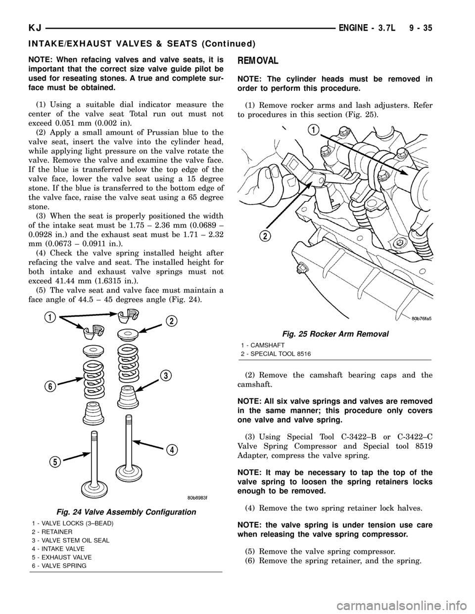
(5) The valve seat and valve face must maintain a
face angle of 44.5 ± 45 degrees angle (Fig. 24).REMOVAL
NOTE: The cylinder heads must be removed in
order to perform this procedure.
(1) Remove rocker arms and lash adjusters. Refer
to procedures in this section (Fig. 25).
(2) Remove the camshaft bearing caps and the
camshaft.
NOTE: All six valve springs and valves are removed
in the same manner; this procedure only covers
one valve and valve spring.
(3) Using Special Tool C-3422±B or C-3422±C
Valve Spring Compressor and Special tool 8519
Adapter, compress the valve spring.
NOTE: It may be necessary to tap the top of the
valve spring to loosen the spring retainers locks
enough to be removed.
(4) Remove the two spring retainer lock halves.
NOTE: the valve spring is under tension use care
when releasing the valve spring compressor.
(5) Remove the valve spring compressor.
(6) Remove the spring retainer, and the spring.
Fig. 24 Valve Assembly Configuration
1 - VALVE LOCKS (3±BEAD)
2 - RETAINER
3 - VALVE STEM OIL SEAL
4 - INTAKE VALVE
5 - EXHAUST VALVE
6 - VALVE SPRING
Fig. 25 Rocker Arm Removal
1 - CAMSHAFT
2 - SPECIAL TOOL 8516
KJENGINE - 3.7L 9 - 35
INTAKE/EXHAUST VALVES & SEATS (Continued)
Page 1254 of 1803
ENGINE BLOCK
DESCRIPTION
The cylinder block is made of cast iron. The block
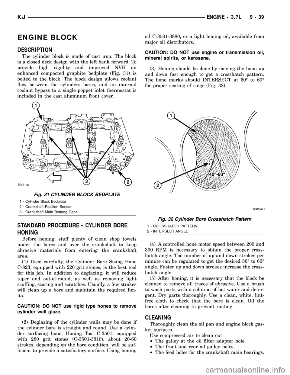
is a closed deck design with the left bank forward. To
provide high rigidity and improved NVH an
enhanced compacted graphite bedplate (Fig. 31) is
bolted to the block. The block design allows coolant
flow between the cylinders bores, and an internal
coolant bypass to a single poppet inlet thermostat is
included in the cast aluminum front cover.
STANDARD PROCEDURE - CYLINDER BORE
HONING
Before honing, stuff plenty of clean shop towels
under the bores and over the crankshaft to keep
abrasive materials from entering the crankshaft
area.
(1) Used carefully, the Cylinder Bore Sizing Hone
C-823, equipped with 220 grit stones, is the best tool
for this job. In addition to deglazing, it will reduce
taper and out-of-round, as well as removing light
scuffing, scoring and scratches. Usually, a few strokes
will clean up a bore and maintain the required lim-
its.
CAUTION: DO NOT use rigid type hones to remove
cylinder wall glaze.
(2) Deglazing of the cylinder walls may be done if
the cylinder bore is straight and round. Use a cylin-
der surfacing hone, Honing Tool C-3501, equipped
with 280 grit stones (C-3501-3810). about 20-60
strokes, depending on the bore condition, will be suf-
ficient to provide a satisfactory surface. Using honingoil C-3501-3880, or a light honing oil, available from
major oil distributors.
CAUTION: DO NOT use engine or transmission oil,
mineral spirits, or kerosene.
(3) Honing should be done by moving the hone up
and down fast enough to get a crosshatch pattern.
The hone marks should INTERSECT at 50É to 60É
for proper seating of rings (Fig. 32).
(4) A controlled hone motor speed between 200 and
300 RPM is necessary to obtain the proper cross-
hatch angle. The number of up and down strokes per
minute can be regulated to get the desired 50É to 60É
angle. Faster up and down strokes increase the cross-
hatch angle.
(5) After honing, it is necessary that the block be
cleaned to remove all traces of abrasive. Use a brush
to wash parts with a solution of hot water and deter-
gent. Dry parts thoroughly. Use a clean, white, lint-
free cloth to check that the bore is clean. Oil the
bores after cleaning to prevent rusting.
CLEANING
Thoroughly clean the oil pan and engine block gas-
ket surfaces.
Use compressed air to clean out:
²The galley at the oil filter adaptor hole.
²The front and rear oil galley holes.
²The feed holes for the crankshaft main bearings.
Fig. 31 CYLINDER BLOCK BEDPLATE
1 - Cylinder Block Bedplate
2 - Crankshaft Position Sensor
3 - Crankshaft Main Bearing Caps
Fig. 32 Cylinder Bore Crosshatch Pattern
1 - CROSSHATCH PATTERN
2 - INTERSECT ANGLE
KJENGINE - 3.7L 9 - 39
Page 1255 of 1803
Once the block has been completely cleaned, apply
Loctite PST pipe sealant with Teflon 592 to the
threads of the front and rear oil galley plugs. Tighten
the plugs to 34 N´m (25 ft. lbs.) torque.
INSPECTION
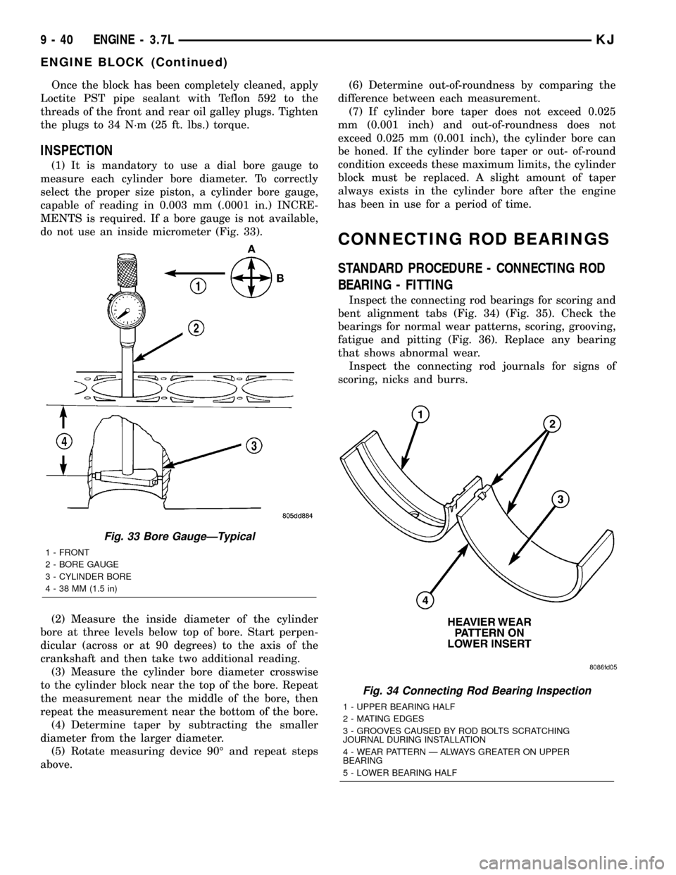
(1) It is mandatory to use a dial bore gauge to
measure each cylinder bore diameter. To correctly
select the proper size piston, a cylinder bore gauge,
capable of reading in 0.003 mm (.0001 in.) INCRE-
MENTS is required. If a bore gauge is not available,
do not use an inside micrometer (Fig. 33).
(2) Measure the inside diameter of the cylinder
bore at three levels below top of bore. Start perpen-
dicular (across or at 90 degrees) to the axis of the
crankshaft and then take two additional reading.
(3) Measure the cylinder bore diameter crosswise
to the cylinder block near the top of the bore. Repeat
the measurement near the middle of the bore, then
repeat the measurement near the bottom of the bore.
(4) Determine taper by subtracting the smaller
diameter from the larger diameter.
(5) Rotate measuring device 90É and repeat steps
above.(6) Determine out-of-roundness by comparing the
difference between each measurement.
(7) If cylinder bore taper does not exceed 0.025
mm (0.001 inch) and out-of-roundness does not
exceed 0.025 mm (0.001 inch), the cylinder bore can
be honed. If the cylinder bore taper or out- of-round
condition exceeds these maximum limits, the cylinder
block must be replaced. A slight amount of taper
always exists in the cylinder bore after the engine
has been in use for a period of time.
CONNECTING ROD BEARINGS
STANDARD PROCEDURE - CONNECTING ROD
BEARING - FITTING
Inspect the connecting rod bearings for scoring and
bent alignment tabs (Fig. 34) (Fig. 35). Check the
bearings for normal wear patterns, scoring, grooving,
fatigue and pitting (Fig. 36). Replace any bearing
that shows abnormal wear.
Inspect the connecting rod journals for signs of
scoring, nicks and burrs.
Fig. 33 Bore GaugeÐTypical
1 - FRONT
2 - BORE GAUGE
3 - CYLINDER BORE
4 - 38 MM (1.5 in)
Fig. 34 Connecting Rod Bearing Inspection
1 - UPPER BEARING HALF
2 - MATING EDGES
3 - GROOVES CAUSED BY ROD BOLTS SCRATCHING
JOURNAL DURING INSTALLATION
4 - WEAR PATTERN Ð ALWAYS GREATER ON UPPER
BEARING
5 - LOWER BEARING HALF
9 - 40 ENGINE - 3.7LKJ
ENGINE BLOCK (Continued)
Page 1275 of 1803

DIAGNOSIS AND TESTING
DIAGNOSIS AND TESTING - ENGINE OIL LEAK
Begin with a thorough visual inspection of the
engine, particularly at the area of the suspected leak.
If an oil leak source is not readily identifiable, the
following steps should be followed:
(1) Do not clean or degrease the engine at this
time because some solvents may cause rubber to
swell, temporarily stopping the leak.
(2) Add an oil soluble dye (use as recommended by
manufacturer). Start the engine and let idle for
approximately 15 minutes. Check the oil dipstick to
make sure the dye is thoroughly mixed as indicated
with a bright yellow color under a black light.
(3) Using a black light, inspect the entire engine
for fluorescent dye, particularly at the suspected area
of oil leak. If the oil leak is found and identified,
repair per service manual instructions.
(4) If dye is not observed, drive the vehicle at var-
ious speeds for approximately 24km (15 miles), and
repeat inspection.If the oil leak source is not pos-
itively identified at this time, proceed with the air
leak detection test method.
Air Leak Detection Test Method
(1) Disconnect the breather cap to air cleaner hose
at the breather cap end. Cap or plug breather cap
nipple.
(2) Remove the PCV valve from the cylinder head
cover. Cap or plug the PCV valve grommet.
(3) Attach an air hose with pressure gauge and
regulator to the dipstick tube.
CAUTION: Do not subject the engine assembly to
more than 20.6 kpa (3 PSI) of test pressure.
(4) Gradually apply air pressure from 1 psi to 2.5
psi maximum while applying soapy water at the sus-
pected source. Adjust the regulator to the suitable
test pressure that provide the best bubbles which
will pinpoint the leak source. If the oil leak is
detected and identified, repair per service manual
procedures.
(5) If the leakage occurs at the rear oil seal area,
refer to the section, Inspection for Rear Seal Area
Leak.
(6) If no leaks are detected, turn off the air supply
and remove the air hose and all plugs and caps.
Install the PCV valve and breather cap hose.
(7) Clean the oil off the suspect oil leak area using
a suitable solvent. Drive the vehicle at various
speeds approximately 24 km (15 miles). Inspect the
engine for signs of an oil leak by using a black light.
INSPECTION FOR REAR SEAL AREA LEAKS
Since it is sometimes difficult to determine the
source of an oil leak in the rear seal area of the
engine, a more involved inspection is necessary. The
following steps should be followed to help pinpoint
the source of the leak.
If the leakage occurs at the crankshaft rear oil seal
area:
(1) Disconnect the battery.
(2) Raise the vehicle.
(3) Remove torque converter or clutch housing
cover and inspect rear of block for evidence of oil.
Use a black light to check for the oil leak:
(a) Circular spray pattern generally indicates
seal leakage or crankshaft damage.
(b) Where leakage tends to run straight down,
possible causes are a porous block, camshaft bore
cup plugs oil galley pipe plugs, oil filter runoff, and
main bearing cap to cylinder block mating sur-
faces.
(4) If no leaks are detected, pressurize the crank-
case as outlined in the, Inspection (Engine oil Leaks
in general)
CAUTION: Do not exceed 20.6 kPa (3 psi).
(5) If the leak is not detected, very slowly turn the
crankshaft and watch for leakage. If a leak is
detected between the crankshaft and seal while
slowly turning the crankshaft, it is possible the
crankshaft seal surface is damaged. The seal area on
the crankshaft could have minor nicks or scratches
that can be polished out with emery cloth.
CAUTION: Use extreme caution when crankshaft
polishing is necessary to remove minor nicks and
scratches. The crankshaft seal flange is especially
machined to complement the function of the rear oil
seal.
(6) For bubbles that remain steady with shaft
rotation, no further inspection can be done until dis-
assembled.
DIAGNOSIS AND TESTING - ENGINE OIL
PRESSURE
(1) Remove oil pressure sending unit (Fig. 70)and
install gauge assembly C-3292.
(2) Run engine until thermostat opens.
(3) Oil Pressure:
²Curb IdleÐ25 Kpa (4 psi) minimum
²3000 rpmÐ170 - 550 KPa (25 - 80 psi)
(4) If oil pressure is 0 at idle, shut off engine.
Check for a clogged oil pick-up screen or a pressure
relief valve stuck open.
9 - 60 ENGINE - 3.7LKJ
LUBRICATION (Continued)
Page 1276 of 1803
DIAGNOSIS AND TESTING - REAR SEAL AREA
LEAKS
Since it is sometimes difficult to determine the
source of an oil leak in the rear seal area of the
engine, a more involved inspection is necessary. The
following steps should be followed to help pinpoint
the source of the leak.
If the leakage occurs at the crankshaft rear oil seal
area:
(1) Disconnect the battery.
(2) Raise the vehicle.
(3) Remove torque converter or clutch housing
cover and inspect rear of block for evidence of oil.
Use a black light to check for the oil leak:
(a) Circular spray pattern generally indicates
seal leakage or crankshaft damage.
(b) Where leakage tends to run straight down,
possible causes are a porous block, camshaft bore
cup plugs, oil galley pipe plugs, oil filter runoff,
and main bearing cap to cylinder block mating sur-
faces. See Engine, for proper repair procedures of
these items.
(4) If no leaks are detected, pressurized the crank-
case as outlined in the section, Inspection (Engine oil
Leaks in general)
CAUTION: Do not exceed 20.6 kPa (3 psi).(5) If the leak is not detected, very slowly turn the
crankshaft and watch for leakage. If a leak is
detected between the crankshaft and seal while
slowly turning the crankshaft, it is possible the
crankshaft seal surface is damaged. The seal area on
the crankshaft could have minor nicks or scratches
that can be polished out with emery cloth.
CAUTION: Use extreme caution when crankshaft
polishing is necessary to remove minor nicks or
scratches. The crankshaft seal flange is specially
machined to complement the function of the rear oil
seal.
(6) For bubbles that remain steady with shaft
rotation, no further inspection can be done until dis-
assembled. (Refer to 9 - ENGINE - DIAGNOSIS AND
TESTING), under the Oil Leak row, for components
inspections on possible causes and corrections.
(7) After the oil leak root cause and appropriate
corrective action have been identified, (Refer to 9 -
ENGINE/ENGINE BLOCK/CRANKSHAFT OIL
SEAL - REAR - REMOVAL).
OIL
STANDARD PROCEDURE - ENGINE OIL
WARNING: NEW OR USED ENGINE OIL CAN BE
IRRITATING TO THE SKIN. AVOID PROLONGED OR
REPEATED SKIN CONTACT WITH ENGINE OIL.
CONTAMINANTS IN USED ENGINE OIL, CAUSED BY
INTERNAL COMBUSTION, CAN BE HAZARDOUS TO
YOUR HEALTH. THOROUGHLY WASH EXPOSED
SKIN WITH SOAP AND WATER. DO NOT WASH
SKIN WITH GASOLINE, DIESEL FUEL, THINNER, OR
SOLVENTS, HEALTH PROBLEMS CAN RESULT. DO
NOT POLLUTE, DISPOSE OF USED ENGINE OIL
PROPERLY.
ENGINE OIL SPECIFICATION
CAUTION: Do not use non-detergent or straight
mineral oil when adding or changing crankcase
lubricant. Engine failure can result.
API SERVICE GRADE CERTIFIED
Use an engine oil that is API Service Grade Certi-
fied. MOPARtprovides engine oils that conform to
this service grade.
SAE VISCOSITY
An SAE viscosity grade is used to specify the vis-
cosity of engine oil. Use only engine oils with multi-
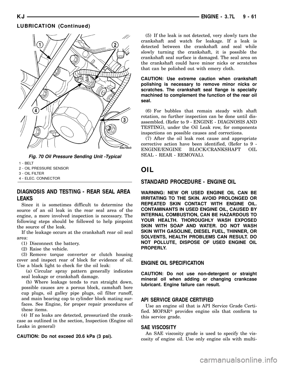
Fig. 70 Oil Pressure Sending Unit -Typical
1 - BELT
2 - OIL PRESSURE SENSOR
3 - OIL FILTER
4 - ELEC. CONNECTOR
KJENGINE - 3.7L 9 - 61
LUBRICATION (Continued)