engine oil JEEP LIBERTY 2002 KJ / 1.G Service Manual
[x] Cancel search | Manufacturer: JEEP, Model Year: 2002, Model line: LIBERTY, Model: JEEP LIBERTY 2002 KJ / 1.GPages: 1803, PDF Size: 62.3 MB
Page 348 of 1803
GENERATOR
DESCRIPTION
The generator is belt-driven by the engine using a
serpentine type drive belt. It is serviced only as a
complete assembly. If the generator fails for any rea-
son, the entire assembly must be replaced.
OPERATION
As the energized rotor begins to rotate within the
generator, the spinning magnetic field induces a cur-
rent into the windings of the stator coil. Once the
generator begins producing sufficient current, it also
provides the current needed to energize the rotor.
The stator winding connections deliver the induced
AC current to 3 positive and 3 negative diodes for
rectification. From the diodes, rectified DC current is
delivered to the vehicle electrical system through the
generator battery terminal.
Although the generators appear the same exter-
nally, different generators with different output rat-
ings are used on this vehicle. Be certain that the
replacement generator has the same output rating
and part number as the original unit. Refer to Spec-
ifications and see Generator Ratings for amperage
ratings and part numbers.
Noise emitting from the generator may be caused
by: worn, loose or defective bearings; a loose or defec-
tive drive pulley; incorrect, worn, damaged or misad-
justed fan drive belt; loose mounting bolts; a
misaligned drive pulley or a defective stator or diode.
REMOVAL
Gasoline Powered Engines
CAUTION: DISCONNECT NEGATIVE CABLE FROM
BATTERY BEFORE REMOVING BATTERY OUTPUT
WIRE FROM GENERATOR. FAILURE TO DO SO
CAN RESULT IN INJURY.
(1) Disconnect and isolate negative battery cable
at battery.
CAUTION: Never force a belt over a pulley rim
using a screwdriver. The synthetic fiber of the belt
can be damaged.CAUTION: When installing a serpentine accessory
drive belt, the belt MUST be routed correctly. The
water pump will be rotating in the wrong direction if
the belt is installed incorrectly, causing the engine
to overheat. Refer to belt routing label in engine
compartment, or refer to Belt Schematics in Cooling
System.
(2) Remove generator drive belt. Refer to 7, Cool-
ing System for procedures.
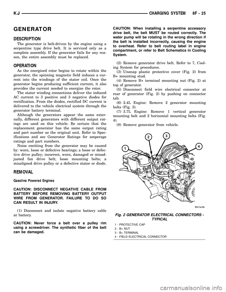
(3) Unsnap plastic protective cover (Fig. 2) from
B+ mounting stud.
(4) Remove B+ terminal mounting nut (Fig. 2) at
top of generator.
(5) Disconnect field wire electrical connector at
rear of generator (Fig. 2) by pushing on connector
tab.
(6) 2.4L Engine: Remove 2 generator mounting
bolts (Fig. 3).
(7) 3.7L Engine: Remove 1 vertical generator
mounting bolt and 2 horizontal mounting bolts (Fig.
4).
(8) Remove generator from vehicle.
Fig. 2 GENERATOR ELECTRICAL CONNECTORS -
TYPICAL
1 - PROTECTIVE CAP
2-B+NUT
3 - B+ TERMINAL
4 - FIELD ELECTRICAL CONNECTOR
KJCHARGING SYSTEM 8F - 25
Page 355 of 1803
STARTING SYSTEM
TABLE OF CONTENTS
page page
STARTING SYSTEM
DESCRIPTION.........................32
OPERATION...........................32
DIAGNOSIS AND TESTING - STARTING
SYSTEM............................33
INSPECTION - STARTING SYSTEM.........37
SPECIFICATIONS
TORQUE - GAS POWERED.............38
STARTER MOTOR - GAS POWERED......39
STARTER MOTOR
DIAGNOSIS AND TESTING - STARTER
MOTOR .............................39REMOVAL.............................39
INSTALLATION.........................41
STARTER MOTOR RELAY
DESCRIPTION.........................41
OPERATION...........................42
DIAGNOSIS AND TESTING -
STARTER RELAY......................42
REMOVAL.............................43
INSTALLATION.........................43
STARTING SYSTEM
DESCRIPTION
The starting system consists of:
²Starter relay
²Starter motor (including an integral starter sole-
noid)
Other components to be considered as part of start-
ing system are:
²Battery
²Battery cables
²Ignition switch and key lock cylinder
²Clutch pedal position switch (manual transmis-
sion)
²Park/neutral position switch (automatic trans-
mission)
²Wire harnesses and connections.
The Battery, Starting, and Charging systems oper-
ate in conjunction with one another, and must be
tested as a complete system. For correct operation of
starting/charging systems, all components used in
these 3 systems must perform within specifications.
When attempting to diagnose any of these systems, it
is important that you keep their interdependency in
mind.
The diagnostic procedures used in each of these
groups include the most basic conventional diagnostic
methods, to the more sophisticated On-Board Diag-
nostics (OBD) built into the Powertrain Control Mod-
ule (PCM). Use of an induction-type milliampere
ammeter, volt/ohmmeter, battery charger, carbon pile
rheostat (load tester), and 12-volt test lamp may be
required.Certain starting system components are monitored
by the PCM and may produce a Diagnostic Trouble
Code (DTC). Refer to Emission Control. See Diagnos-
tic Trouble Codes for additional information and a
list of codes.
OPERATION
The starting system components form two separate
circuits. A high-amperage feed circuit that feeds the
starter motor between 150 and 350 amperes (700
amperes - diesel engine), and a low-amperage control
circuit that operates on less than 20 amperes. The
high-amperage feed circuit components include the
battery, the battery cables, the contact disc portion of
the starter solenoid, and the starter motor. The low-
amperage control circuit components include the igni-
tion switch, the clutch pedal position switch (manual
transmission), the park/neutral position switch (auto-
matic transmission), the starter relay, the electro-
magnetic windings of the starter solenoid, and the
connecting wire harness components.
If the vehicle is equipped with a manual transmis-
sion, it has a clutch pedal position switch installed in
series between the ignition switch and the coil bat-
tery terminal of the starter relay. This normally open
switch prevents the starter relay from being ener-
gized when the ignition switch is turned to the
momentary Start position, unless the clutch pedal is
depressed. This feature prevents starter motor oper-
ation while the clutch disc and the flywheel are
engaged. The starter relay coil ground terminal is
always grounded on vehicles with a manual trans-
mission.
8F - 32 STARTING SYSTEMKJ
Page 356 of 1803
If the vehicle is equipped with an automatic trans-
mission, battery voltage is supplied through the low-
amperage control circuit to the coil battery terminal
of the starter relay when the ignition switch is
turned to the momentary Start position. The park/
neutral position switch is installed in series between
the starter relay coil ground terminal and ground.
This normally open switch prevents the starter relay
from being energized and the starter motor from
operating unless the automatic transmission gear
selector is in the Neutral or Park positions.
When the starter relay coil is energized, the nor-
mally open relay contacts close. The relay contacts
connect the relay common feed terminal to the relay
normally open terminal. The closed relay contacts
energize the starter solenoid coil windings.
The energized solenoid pull-in coil pulls in the sole-
noid plunger. The solenoid plunger pulls the shift
lever in the starter motor. This engages the starter
overrunning clutch and pinion gear with the starter
ring gear on the manual transmission flywheel or on
the automatic transmission torque converter or
torque converter drive plate.
As the solenoid plunger reaches the end of its
travel, the solenoid contact disc completes the high-
amperage starter feed circuit and energizes the sole-
noid plunger hold-in coil. Current now flows betweenthe solenoid battery terminal and the starter motor,
energizing the starter.
Once the engine starts, the overrunning clutch pro-
tects the starter motor from damage by allowing the
starter pinion gear to spin faster than the pinion
shaft. When the driver releases the ignition switch to
the On position, the starter relay coil is de-energized.
This causes the relay contacts to open. When the
relay contacts open, the starter solenoid plunger
hold-in coil is de-energized.
When the solenoid plunger hold-in coil is de-ener-
gized, the solenoid plunger return spring returns the
plunger to its relaxed position. This causes the con-
tact disc to open the starter feed circuit, and the shift
lever to disengage the overrunning clutch and pinion
gear from the starter ring gear.
DIAGNOSIS AND TESTING - STARTING
SYSTEM
The battery, starting, and charging systems oper-
ate in conjunction with one another, and must be
tested as a complete system. For correct starting/
charging system operation, all of the components
involved in these 3 systems must perform within
specifications.
Starting System Diagnosis
CONDITION POSSIBLE CAUSE CORRECTION
STARTER FAILS TO
OPERATE.1. Battery discharged or
faulty.1. Refer to Battery. Charge or replace battery, if required.
2. Starting circuit wiring
faulty.2. Refer to 8, Wiring Diagrams. Test and repair starter
feed and/or control circuits, if required.
3. Starter relay faulty. 3. Refer to Starter Relay in Diagnosis and Testing.
Replace starter relay if required.
4. Ignition switch faulty. 4. Refer to Ignition Switch and Key Lock Cylinder.
Replace ignition switch if required.
5. Clutch pedal position
switch faulty.5. Refer to Clutch Pedal Position Switch.
6. Park/Neutral position
switch faulty or
misadjusted.6. Refer to Park/Neutral Position Switch. Replace
park/neutral position switch if required.
7. Starter solenoid faulty. 7. Refer to Starter Motor. Replace starter motor assembly
if required.
8. Starter motor faulty. 8. If all other starting system components and circuits test
OK, replace starter motor.
KJSTARTING SYSTEM 8F - 33
STARTING SYSTEM (Continued)
Page 362 of 1803
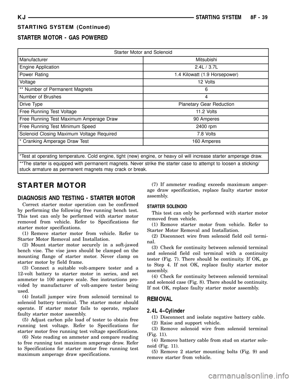
STARTER MOTOR - GAS POWERED
Starter Motor and Solenoid
Manufacturer Mitsubishi
Engine Application 2.4L / 3.7L
Power Rating 1.4 Kilowatt (1.9 Horsepower)
Voltage12 Volts
** Number of Permanent Magnets 6
Number of Brushes 4
Drive Type Planetary Gear Reduction
Free Running Test Voltage 11.2 Volts
Free Running Test Maximum Amperage Draw 90 Amperes
Free Running Test Minimum Speed 2400 rpm
Solenoid Closing Maximum Voltage Required 7.8 Volts
* Cranking Amperage Draw Test 160 Amperes
*Test at operating temperature. Cold engine, tight (new) engine, or heavy oil will increase starter amperage draw.
**The starter is equipped with permanent magnets. Never strike the starter case to attempt to loosen a sticking/
stuck armature as permanent magnets may crack or break.
STARTER MOTOR
DIAGNOSIS AND TESTING - STARTER MOTOR
Correct starter motor operation can be confirmed
by performing the following free running bench test.
This test can only be performed with starter motor
removed from vehicle. Refer to Specifications for
starter motor specifications.
(1) Remove starter motor from vehicle. Refer to
Starter Motor Removal and Installation.
(2) Mount starter motor securely in a soft-jawed
bench vise. The vise jaws should be clamped on the
mounting flange of starter motor. Never clamp on
starter motor by field frame.
(3) Connect a suitable volt-ampere tester and a
12-volt battery to starter motor in series, and set
ammeter to 100 ampere scale. See instructions pro-
vided by manufacturer of volt-ampere tester being
used.
(4) Install jumper wire from solenoid terminal to
solenoid battery terminal. The starter motor should
operate. If starter motor fails to operate, replace
faulty starter motor assembly.
(5) Adjust carbon pile load of tester to obtain free
running test voltage. Refer to Specifications for
starter motor free running test voltage specifications.
(6) Note reading on ammeter and compare reading
to free running test maximum amperage draw. Refer
to Specifications for starter motor free running test
maximum amperage draw specifications.(7) If ammeter reading exceeds maximum amper-
age draw specification, replace faulty starter motor
assembly.
STARTER SOLENOID
This test can only be performed with starter motor
removed from vehicle.
(1) Remove starter motor from vehicle. Refer to
Starter Motor Removal and Installation.
(2) Disconnect wire from solenoid field coil termi-
nal.
(3) Check for continuity between solenoid terminal
and solenoid field coil terminal with a continuity
tester (Fig. 7). There should be continuity. If OK, go
to Step 4. If not OK, replace faulty starter motor
assembly.
(4) Check for continuity between solenoid terminal
and solenoid case (Fig. 8). There should be continuity.
If not OK, replace faulty starter motor assembly.
REMOVAL
2.4L 4±Cylinder
(1) Disconnect and isolate negative battery cable.
(2) Raise and support vehicle.
(3) Remove solenoid wire from solenoid terminal
(Fig. 11).
(4) Remove battery cable from stud on starter sole-
noid (Fig. 11).
(5) Remove 2 starter mounting bolts (Fig. 9) and
remove starter from vehicle.
KJSTARTING SYSTEM 8F - 39
STARTING SYSTEM (Continued)
Page 364 of 1803
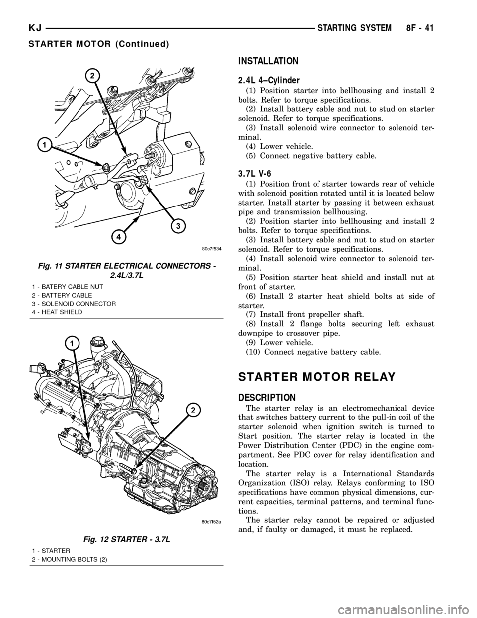
INSTALLATION
2.4L 4±Cylinder
(1) Position starter into bellhousing and install 2
bolts. Refer to torque specifications.
(2) Install battery cable and nut to stud on starter
solenoid. Refer to torque specifications.
(3) Install solenoid wire connector to solenoid ter-
minal.
(4) Lower vehicle.
(5) Connect negative battery cable.
3.7L V-6
(1) Position front of starter towards rear of vehicle
with solenoid position rotated until it is located below
starter. Install starter by passing it between exhaust
pipe and transmission bellhousing.
(2) Position starter into bellhousing and install 2
bolts. Refer to torque specifications.
(3) Install battery cable and nut to stud on starter
solenoid. Refer to torque specifications.
(4) Install solenoid wire connector to solenoid ter-
minal.
(5) Position starter heat shield and install nut at
front of starter.
(6) Install 2 starter heat shield bolts at side of
starter.
(7) Install front propeller shaft.
(8) Install 2 flange bolts securing left exhaust
downpipe to crossover pipe.
(9) Lower vehicle.
(10) Connect negative battery cable.
STARTER MOTOR RELAY
DESCRIPTION
The starter relay is an electromechanical device
that switches battery current to the pull-in coil of the
starter solenoid when ignition switch is turned to
Start position. The starter relay is located in the
Power Distribution Center (PDC) in the engine com-
partment. See PDC cover for relay identification and
location.
The starter relay is a International Standards
Organization (ISO) relay. Relays conforming to ISO
specifications have common physical dimensions, cur-
rent capacities, terminal patterns, and terminal func-
tions.
The starter relay cannot be repaired or adjusted
and, if faulty or damaged, it must be replaced.
Fig. 11 STARTER ELECTRICAL CONNECTORS -
2.4L/3.7L
1 - BATERY CABLE NUT
2 - BATTERY CABLE
3 - SOLENOID CONNECTOR
4 - HEAT SHIELD
Fig. 12 STARTER - 3.7L
1-STARTER
2 - MOUNTING BOLTS (2)
KJSTARTING SYSTEM 8F - 41
STARTER MOTOR (Continued)
Page 365 of 1803
OPERATION
The ISO relay consists of an electromagnetic coil, a
resistor or diode, and three (two fixed and one mov-
able) electrical contacts. The movable (common feed)
relay contact is held against one of the fixed contacts
(normally closed) by spring pressure. When electro-
magnetic coil is energized, it draws the movable con-
tact away from normally closed fixed contact, and
holds it against the other (normally open) fixed con-
tact.
When electromagnetic coil is de-energized, spring
pressure returns movable contact to normally closed
position. The resistor or diode is connected in parallel
with electromagnetic coil within relay, and helps to
dissipate voltage spikes produced when coil is de-en-
ergized.
DIAGNOSIS AND TESTING - STARTER RELAY
The starter relay is located in the Power Distribu-
tion Center (PDC) in engine compartment. Refer to
label on PDC cover for relay location.
RELAY TEST
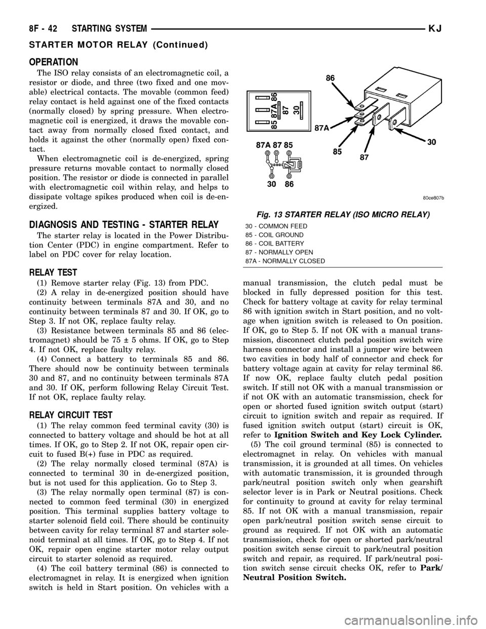
(1) Remove starter relay (Fig. 13) from PDC.
(2) A relay in de-energized position should have
continuity between terminals 87A and 30, and no
continuity between terminals 87 and 30. If OK, go to
Step 3. If not OK, replace faulty relay.
(3) Resistance between terminals 85 and 86 (elec-
tromagnet) should be 75 5 ohms. If OK, go to Step
4. If not OK, replace faulty relay.
(4) Connect a battery to terminals 85 and 86.
There should now be continuity between terminals
30 and 87, and no continuity between terminals 87A
and 30. If OK, perform following Relay Circuit Test.
If not OK, replace faulty relay.
RELAY CIRCUIT TEST
(1) The relay common feed terminal cavity (30) is
connected to battery voltage and should be hot at all
times. If OK, go to Step 2. If not OK, repair open cir-
cuit to fused B(+) fuse in PDC as required.
(2) The relay normally closed terminal (87A) is
connected to terminal 30 in de-energized position,
but is not used for this application. Go to Step 3.
(3) The relay normally open terminal (87) is con-
nected to common feed terminal (30) in energized
position. This terminal supplies battery voltage to
starter solenoid field coil. There should be continuity
between cavity for relay terminal 87 and starter sole-
noid terminal at all times. If OK, go to Step 4. If not
OK, repair open engine starter motor relay output
circuit to starter solenoid as required.
(4) The coil battery terminal (86) is connected to
electromagnet in relay. It is energized when ignition
switch is held in Start position. On vehicles with amanual transmission, the clutch pedal must be
blocked in fully depressed position for this test.
Check for battery voltage at cavity for relay terminal
86 with ignition switch in Start position, and no volt-
age when ignition switch is released to On position.
If OK, go to Step 5. If not OK with a manual trans-
mission, disconnect clutch pedal position switch wire
harness connector and install a jumper wire between
two cavities in body half of connector and check for
battery voltage again at cavity for relay terminal 86.
If now OK, replace faulty clutch pedal position
switch. If still not OK with a manual transmission or
if not OK with an automatic transmission, check for
open or shorted fused ignition switch output (start)
circuit to ignition switch and repair as required. If
fused ignition switch output (start) circuit is OK,
refer toIgnition Switch and Key Lock Cylinder.
(5) The coil ground terminal (85) is connected to
electromagnet in relay. On vehicles with manual
transmission, it is grounded at all times. On vehicles
with automatic transmission, it is grounded through
park/neutral position switch only when gearshift
selector lever is in Park or Neutral positions. Check
for continuity to ground at cavity for relay terminal
85. If not OK with a manual transmission, repair
open park/neutral position switch sense circuit to
ground as required. If not OK with an automatic
transmission, check for open or shorted park/neutral
position switch sense circuit to park/neutral position
switch and repair, as required. If park/neutral posi-
tion switch sense circuit checks OK, refer toPark/
Neutral Position Switch.
Fig. 13 STARTER RELAY (ISO MICRO RELAY)
30 - COMMON FEED
85 - COIL GROUND
86 - COIL BATTERY
87 - NORMALLY OPEN
87A - NORMALLY CLOSED
8F - 42 STARTING SYSTEMKJ
STARTER MOTOR RELAY (Continued)
Page 388 of 1803
IGNITION CONTROL
TABLE OF CONTENTS
page page
IGNITION CONTROL
DESCRIPTION..........................1
OPERATION............................1
SPECIFICATIONS
SPECIFICATIONS - IGNITION TIMING.......2
ENGINE FIRING ORDER - 2.4L 4-CYLINDER . 2
ENGINE FIRING ORDER - 3.7L V-6.........2
IGNITION COIL RESISTANCE - 2.4L........2
IGNITION COIL RESISTANCE - 3.7L V-6.....3
SPARK PLUGS........................3
SPARK PLUG CABLE RESISTANCE - 2.4L . . . 3
TORQUE - IGNITION SYSTEM............3
AUTO SHUT DOWN RELAY
DESCRIPTION - PCM OUTPUT.............4
OPERATION
OPERATION - ASD SENSE - PCM INPUT....4
OPERATION - PCM OUTPUT.............4
DIAGNOSIS AND TESTING - ASD AND FUEL
PUMP RELAYS........................4
REMOVAL.............................5
INSTALLATION..........................5
CAMSHAFT POSITION SENSOR
DESCRIPTION
DESCRIPTION - 2.4L....................5
DESCRIPTION-3.7L.....................6
OPERATION
OPERATION - 2.4L.....................6OPERATION - 3.7L.....................6
REMOVAL.............................7
INSTALLATION..........................8
IGNITION COIL
DESCRIPTION..........................9
OPERATION............................9
REMOVAL.............................10
INSTALLATION.........................10
KNOCK SENSOR
DESCRIPTION.........................11
OPERATION...........................11
REMOVAL.............................12
INSTALLATION.........................12
SPARK PLUG
DESCRIPTION.........................12
OPERATION...........................12
DIAGNOSIS AND TESTING - SPARK PLUG
CONDITIONS.........................13
REMOVAL.............................15
CLEANING SPARK PLUGS................15
INSTALLATION.........................15
IGNITION COIL CAPACITOR
DESCRIPTION.........................16
OPERATION...........................16
REMOVAL.............................16
INSTALLATION.........................16
IGNITION CONTROL
DESCRIPTION
The ignition system consists of:
²Spark Plugs
²Ignition Coil(s)
²Powertrain Control Module (PCM)
²Crankshaft Position Sensor
²2 Knock Sensors (3.7L only)
²Camshaft Position Sensor
²The MAP, TPS, IAC and ECT also have an effect
on the control of the ignition system.
OPERATION
2.4L
A common ignition coil divided into 2 halves is
used. Secondary, high-tension spark plug cables are
also used. One half of the coil fires two spark plugs
simultaneously (one plug is the cylinder under com-pression, and the other plug is the cylinder on the
exhaust stroke). Coil half number one fires cylinders
1 and 4. Coil half number two fires cylinders 2 and 3.
The PCM determines which of the coils to charge and
fire at the correct time.
The Auto Shutdown (ASD) relay provides battery
voltage to the ignition coil. The PCM provides a
ground contact (circuit) for energizing the coil. When
the PCM breaks the contact, the energy in the coil
primary transfers to the secondary causing a spark.
The PCM will de-energize the ASD relay if it does
not receive inputs from either the crankshaft or cam-
shaft position sensors.
A distributor is not used with the 2.4L engine.
3.7L
The 3.7L V6 engine uses a separate ignition coil for
each cylinder. The one-piece coil bolts directly to the
cylinder head. Rubber boots seal the secondary ter-
minal ends of the coils to the top of all 6 spark plugs.
A separate electrical connector is used for each coil.
KJIGNITION CONTROL 8I - 1
Page 389 of 1803
Because of coil design, spark plug cables (second-
ary cables) are not used. A distributor is not used
with the 3.7L engine.
Two knock sensors (one for each cylinder bank) are
used to help control spark knock.
The Auto Shutdown (ASD) relay provides battery
voltage to each ignition coil. The Powertrain Control
Module (PCM) provides a ground contact (circuit) for
energizing each coil. When the PCM breaks the con-
tact, the energy in the coil primary transfers to the
secondary causing a spark. The PCM will de-energize
the ASD relay if it does not receive inputs from
either the crankshaft or camshaft position sensors.
SPECIFICATIONS
SPECIFICATIONS - IGNITION TIMING
Ignition timing is not adjustable on any
engine.
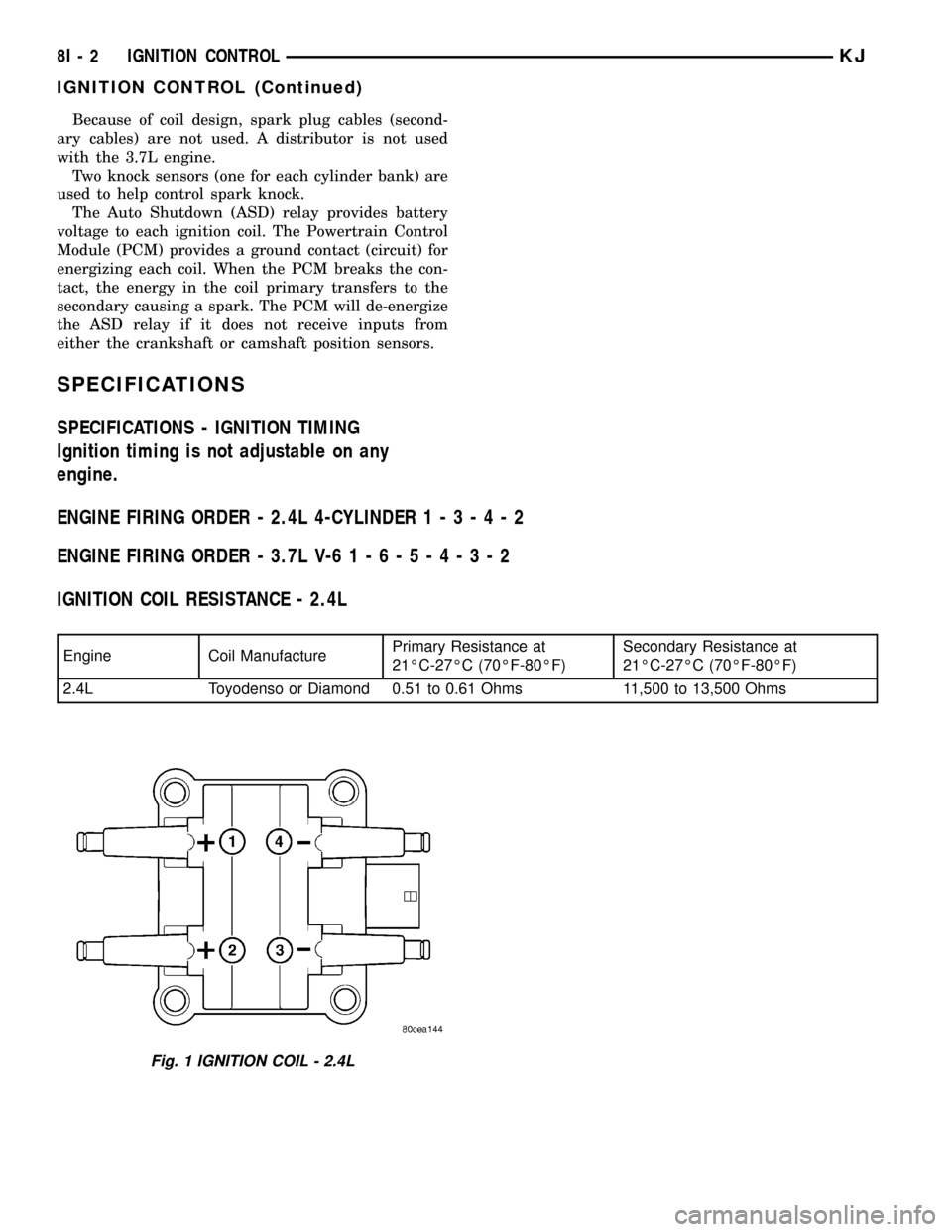
ENGINE FIRING ORDER - 2.4L 4-CYLINDER1-3-4-2
ENGINE FIRING ORDER - 3.7L V-61-6-5-4-3-2
IGNITION COIL RESISTANCE - 2.4L
Engine Coil ManufacturePrimary Resistance at
21ÉC-27ÉC (70ÉF-80ÉF)Secondary Resistance at
21ÉC-27ÉC (70ÉF-80ÉF)
2.4L Toyodenso or Diamond 0.51 to 0.61 Ohms 11,500 to 13,500 Ohms
Fig. 1 IGNITION COIL - 2.4L
8I - 2 IGNITION CONTROLKJ
IGNITION CONTROL (Continued)
Page 390 of 1803
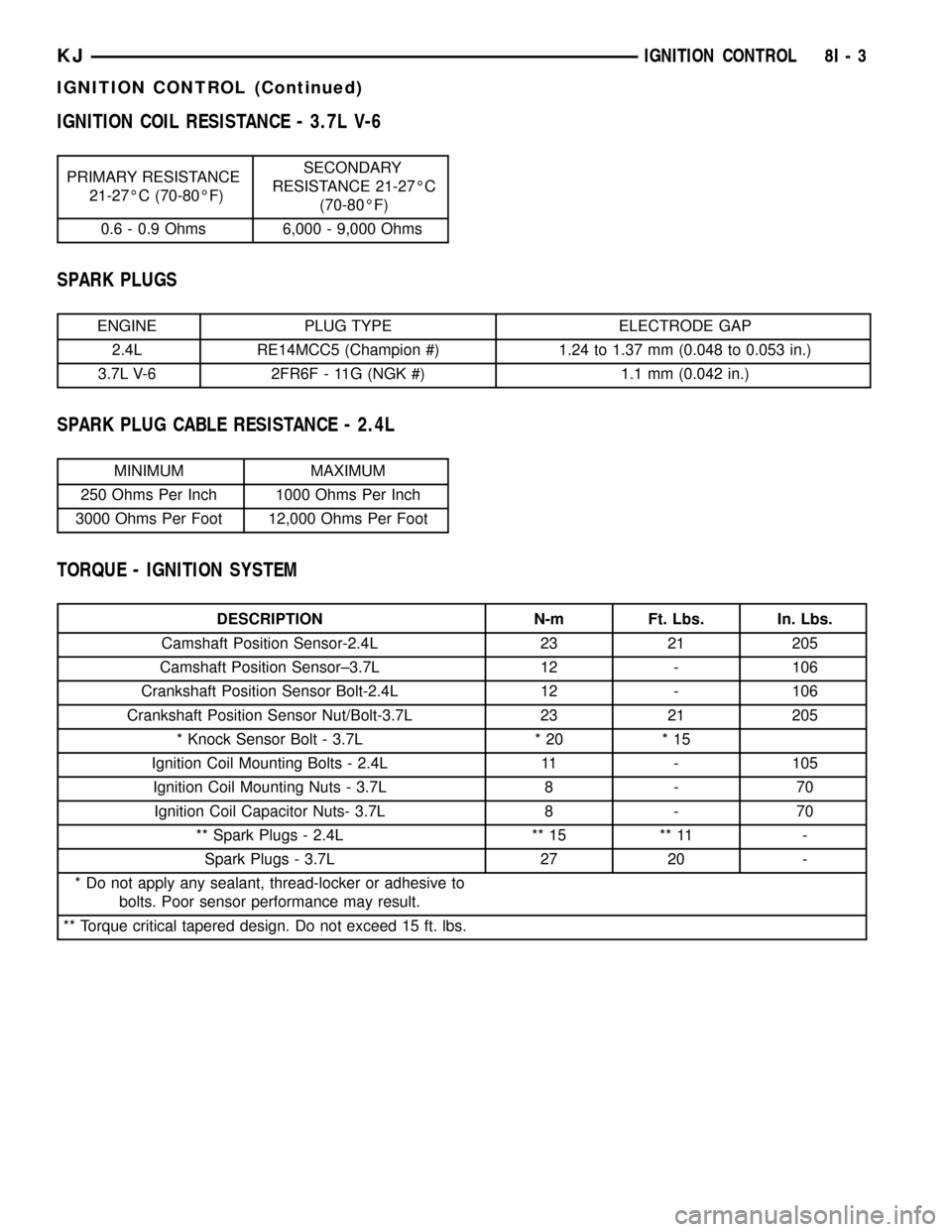
IGNITION COIL RESISTANCE - 3.7L V-6
PRIMARY RESISTANCE
21-27ÉC (70-80ÉF)SECONDARY
RESISTANCE 21-27ÉC
(70-80ÉF)
0.6 - 0.9 Ohms 6,000 - 9,000 Ohms
SPARK PLUGS
ENGINE PLUG TYPE ELECTRODE GAP
2.4L RE14MCC5 (Champion #) 1.24 to 1.37 mm (0.048 to 0.053 in.)
3.7L V-6 2FR6F - 11G (NGK #) 1.1 mm (0.042 in.)
SPARK PLUG CABLE RESISTANCE - 2.4L
MINIMUM MAXIMUM
250 Ohms Per Inch 1000 Ohms Per Inch
3000 Ohms Per Foot 12,000 Ohms Per Foot
TORQUE - IGNITION SYSTEM
DESCRIPTION N-m Ft. Lbs. In. Lbs.
Camshaft Position Sensor-2.4L 23 21 205
Camshaft Position Sensor±3.7L 12 - 106
Crankshaft Position Sensor Bolt-2.4L 12 - 106
Crankshaft Position Sensor Nut/Bolt-3.7L 23 21 205
* Knock Sensor Bolt - 3.7L * 20 * 15
Ignition Coil Mounting Bolts - 2.4L 11 - 105
Ignition Coil Mounting Nuts - 3.7L 8 - 70
Ignition Coil Capacitor Nuts- 3.7L 8 - 70
** Spark Plugs - 2.4L ** 15 ** 11 -
Spark Plugs - 3.7L 27 20 -
* Do not apply any sealant, thread-locker or adhesive to
bolts. Poor sensor performance may result.
** Torque critical tapered design. Do not exceed 15 ft. lbs.
KJIGNITION CONTROL 8I - 3
IGNITION CONTROL (Continued)
Page 391 of 1803
AUTO SHUT DOWN RELAY
DESCRIPTION - PCM OUTPUT
The 5±pin, 12±volt, Automatic Shutdown (ASD)
relay is located in the Power Distribution Center
(PDC). Refer to label on PDC cover for relay location.
OPERATION
OPERATION - ASD SENSE - PCM INPUT
A 12 volt signal at this input indicates to the PCM
that the ASD has been activated. The relay is used to
connect the oxygen sensor heater elements, oxygen
sensor heater relay, ignition coil and fuel injectors to
12 volt + power supply.
This input is used only to sense that the ASD relay
is energized. If the Powertrain Control Module
(PCM) does not see 12 volts at this input when the
ASD should be activated, it will set a Diagnostic
Trouble Code (DTC).
OPERATION - PCM OUTPUT
The ASD relay supplies battery voltage (12+ volts)
to the fuel injectors and ignition coil(s). With certain
emissions packages it also supplies 12±volts to the
oxygen sensor heating elements and the oxygen sen-
sor heater relay.
The ground circuit for the coil within the ASD
relay is controlled by the Powertrain Control Module
(PCM). The PCM operates the ASD relay by switch-
ing its ground circuit on and off.
The ASD relay will be shut±down, meaning the
12±volt power supply to the ASD relay will be de-ac-
tivated by the PCM if the ignition key is left in the
ON position. This is if the engine has not been run-
ning for approximately 1.8 seconds.
DIAGNOSIS AND TESTING - ASD AND FUEL
PUMP RELAYS
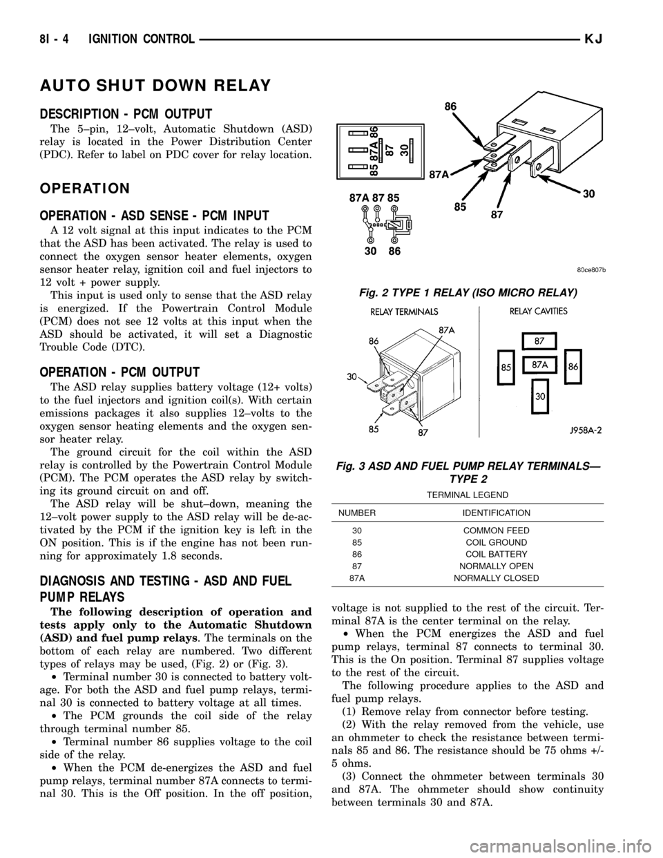
The following description of operation and
tests apply only to the Automatic Shutdown
(ASD) and fuel pump relays. The terminals on the
bottom of each relay are numbered. Two different
types of relays may be used, (Fig. 2) or (Fig. 3).
²Terminal number 30 is connected to battery volt-
age. For both the ASD and fuel pump relays, termi-
nal 30 is connected to battery voltage at all times.
²The PCM grounds the coil side of the relay
through terminal number 85.
²Terminal number 86 supplies voltage to the coil
side of the relay.
²When the PCM de-energizes the ASD and fuel
pump relays, terminal number 87A connects to termi-
nal 30. This is the Off position. In the off position,voltage is not supplied to the rest of the circuit. Ter-
minal 87A is the center terminal on the relay.
²When the PCM energizes the ASD and fuel
pump relays, terminal 87 connects to terminal 30.
This is the On position. Terminal 87 supplies voltage
to the rest of the circuit.
The following procedure applies to the ASD and
fuel pump relays.
(1) Remove relay from connector before testing.
(2) With the relay removed from the vehicle, use
an ohmmeter to check the resistance between termi-
nals 85 and 86. The resistance should be 75 ohms +/-
5 ohms.
(3) Connect the ohmmeter between terminals 30
and 87A. The ohmmeter should show continuity
between terminals 30 and 87A.
Fig. 2 TYPE 1 RELAY (ISO MICRO RELAY)
Fig. 3 ASD AND FUEL PUMP RELAY TERMINALSÐ
TYPE 2
TERMINAL LEGEND
NUMBER IDENTIFICATION
30 COMMON FEED
85 COIL GROUND
86 COIL BATTERY
87 NORMALLY OPEN
87A NORMALLY CLOSED
8I - 4 IGNITION CONTROLKJ