Power seat JEEP LIBERTY 2002 KJ / 1.G Repair Manual
[x] Cancel search | Manufacturer: JEEP, Model Year: 2002, Model line: LIBERTY, Model: JEEP LIBERTY 2002 KJ / 1.GPages: 1803, PDF Size: 62.3 MB
Page 1135 of 1803
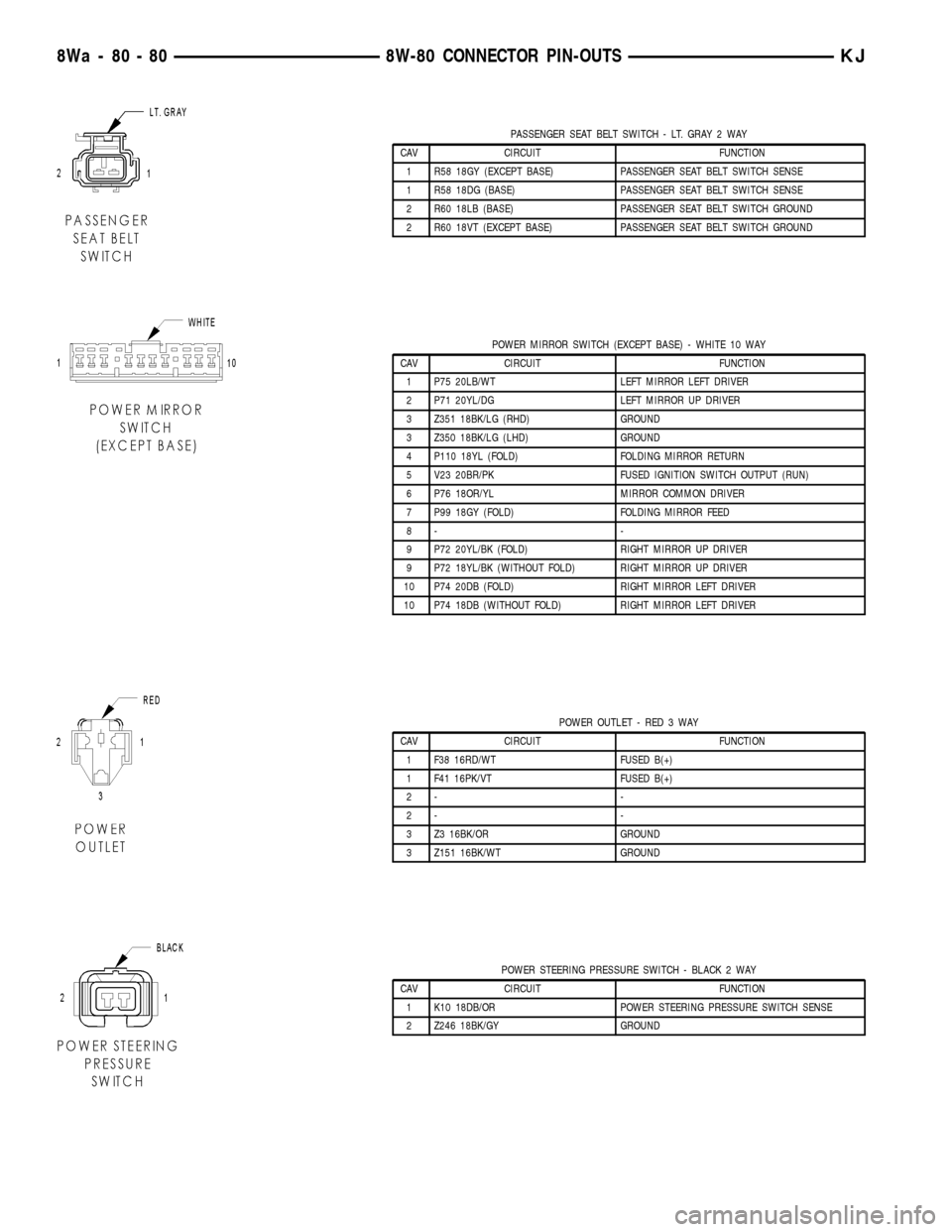
PASSENGER SEAT BELT SWITCH - LT. GRAY 2 WAY
CAV CIRCUIT FUNCTION
1 R58 18GY (EXCEPT BASE) PASSENGER SEAT BELT SWITCH SENSE
1 R58 18DG (BASE) PASSENGER SEAT BELT SWITCH SENSE
2 R60 18LB (BASE) PASSENGER SEAT BELT SWITCH GROUND
2 R60 18VT (EXCEPT BASE) PASSENGER SEAT BELT SWITCH GROUND
POWER MIRROR SWITCH (EXCEPT BASE) - WHITE 10 WAY
CAV CIRCUIT FUNCTION
1 P75 20LB/WT LEFT MIRROR LEFT DRIVER
2 P71 20YL/DG LEFT MIRROR UP DRIVER
3 Z351 18BK/LG (RHD) GROUND
3 Z350 18BK/LG (LHD) GROUND
4 P110 18YL (FOLD) FOLDING MIRROR RETURN
5 V23 20BR/PK FUSED IGNITION SWITCH OUTPUT (RUN)
6 P76 18OR/YL MIRROR COMMON DRIVER
7 P99 18GY (FOLD) FOLDING MIRROR FEED
8- -
9 P72 20YL/BK (FOLD) RIGHT MIRROR UP DRIVER
9 P72 18YL/BK (WITHOUT FOLD) RIGHT MIRROR UP DRIVER
10 P74 20DB (FOLD) RIGHT MIRROR LEFT DRIVER
10 P74 18DB (WITHOUT FOLD) RIGHT MIRROR LEFT DRIVER
POWER OUTLET - RED 3 WAY
CAV CIRCUIT FUNCTION
1 F38 16RD/WT FUSED B(+)
1 F41 16PK/VT FUSED B(+)
2- -
2- -
3 Z3 16BK/OR GROUND
3 Z151 16BK/WT GROUND
POWER STEERING PRESSURE SWITCH - BLACK 2 WAY
CAV CIRCUIT FUNCTION
1 K10 18DB/OR POWER STEERING PRESSURE SWITCH SENSE
2 Z246 18BK/GY GROUND
8Wa - 80 - 80 8W-80 CONNECTOR PIN-OUTSKJ
Page 1146 of 1803
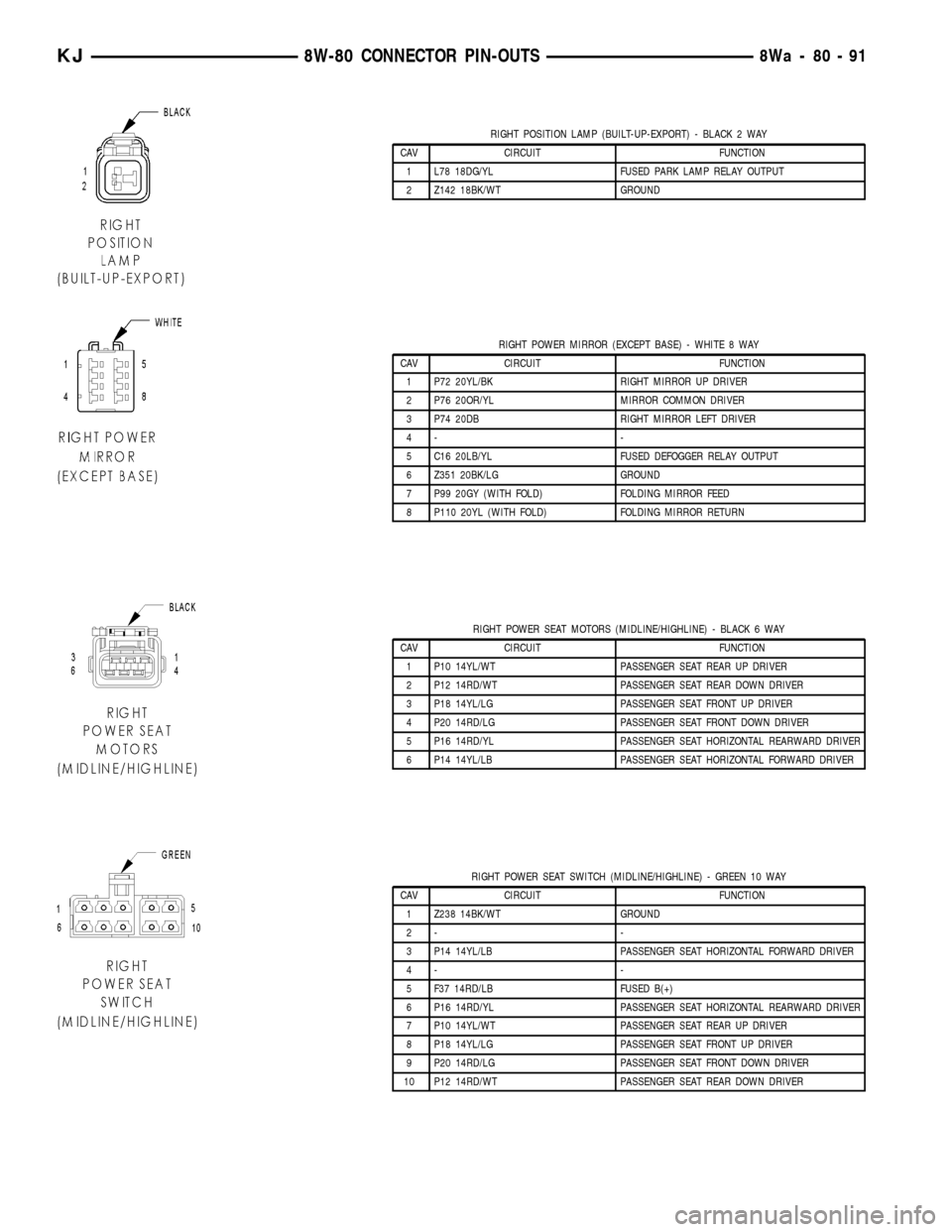
RIGHT POSITION LAMP (BUILT-UP-EXPORT) - BLACK 2 WAY
CAV CIRCUIT FUNCTION
1 L78 18DG/YL FUSED PARK LAMP RELAY OUTPUT
2 Z142 18BK/WT GROUND
RIGHT POWER MIRROR (EXCEPT BASE) - WHITE 8 WAY
CAV CIRCUIT FUNCTION
1 P72 20YL/BK RIGHT MIRROR UP DRIVER
2 P76 20OR/YL MIRROR COMMON DRIVER
3 P74 20DB RIGHT MIRROR LEFT DRIVER
4- -
5 C16 20LB/YL FUSED DEFOGGER RELAY OUTPUT
6 Z351 20BK/LG GROUND
7 P99 20GY (WITH FOLD) FOLDING MIRROR FEED
8 P110 20YL (WITH FOLD) FOLDING MIRROR RETURN
RIGHT POWER SEAT MOTORS (MIDLINE/HIGHLINE) - BLACK 6 WAY
CAV CIRCUIT FUNCTION
1 P10 14YL/WT PASSENGER SEAT REAR UP DRIVER
2 P12 14RD/WT PASSENGER SEAT REAR DOWN DRIVER
3 P18 14YL/LG PASSENGER SEAT FRONT UP DRIVER
4 P20 14RD/LG PASSENGER SEAT FRONT DOWN DRIVER
5 P16 14RD/YL PASSENGER SEAT HORIZONTAL REARWARD DRIVER
6 P14 14YL/LB PASSENGER SEAT HORIZONTAL FORWARD DRIVER
RIGHT POWER SEAT SWITCH (MIDLINE/HIGHLINE) - GREEN 10 WAY
CAV CIRCUIT FUNCTION
1 Z238 14BK/WT GROUND
2- -
3 P14 14YL/LB PASSENGER SEAT HORIZONTAL FORWARD DRIVER
4- -
5 F37 14RD/LB FUSED B(+)
6 P16 14RD/YL PASSENGER SEAT HORIZONTAL REARWARD DRIVER
7 P10 14YL/WT PASSENGER SEAT REAR UP DRIVER
8 P18 14YL/LG PASSENGER SEAT FRONT UP DRIVER
9 P20 14RD/LG PASSENGER SEAT FRONT DOWN DRIVER
10 P12 14RD/WT PASSENGER SEAT REAR DOWN DRIVER
KJ8W-80 CONNECTOR PIN-OUTS8Wa-80-91
Page 1161 of 1803
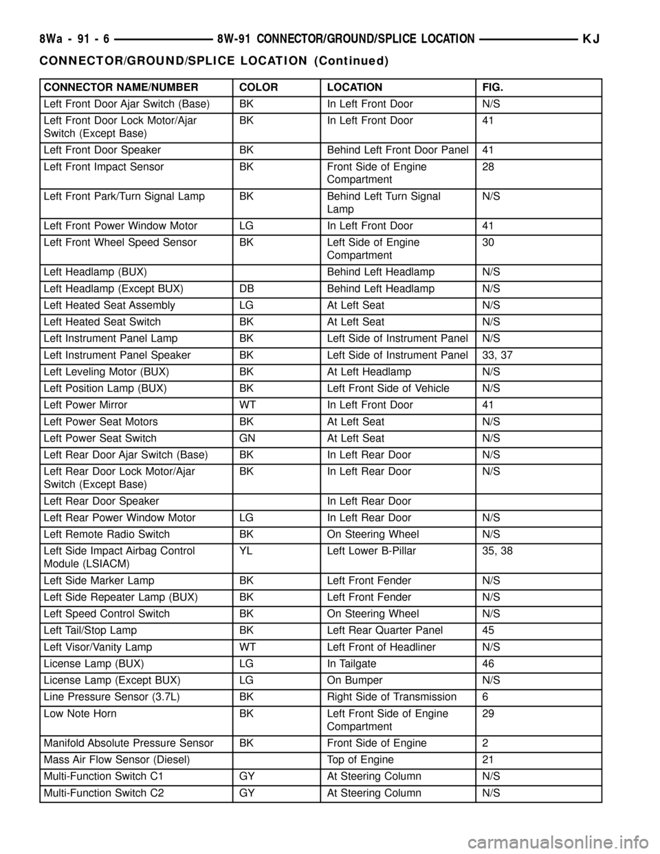
CONNECTOR NAME/NUMBER COLOR LOCATION FIG.
Left Front Door Ajar Switch (Base) BK In Left Front Door N/S
Left Front Door Lock Motor/Ajar
Switch (Except Base)BK In Left Front Door 41
Left Front Door Speaker BK Behind Left Front Door Panel 41
Left Front Impact Sensor BK Front Side of Engine
Compartment28
Left Front Park/Turn Signal Lamp BK Behind Left Turn Signal
LampN/S
Left Front Power Window Motor LG In Left Front Door 41
Left Front Wheel Speed Sensor BK Left Side of Engine
Compartment30
Left Headlamp (BUX) Behind Left Headlamp N/S
Left Headlamp (Except BUX) DB Behind Left Headlamp N/S
Left Heated Seat Assembly LG At Left Seat N/S
Left Heated Seat Switch BK At Left Seat N/S
Left Instrument Panel Lamp BK Left Side of Instrument Panel N/S
Left Instrument Panel Speaker BK Left Side of Instrument Panel 33, 37
Left Leveling Motor (BUX) BK At Left Headlamp N/S
Left Position Lamp (BUX) BK Left Front Side of Vehicle N/S
Left Power Mirror WT In Left Front Door 41
Left Power Seat Motors BK At Left Seat N/S
Left Power Seat Switch GN At Left Seat N/S
Left Rear Door Ajar Switch (Base) BK In Left Rear Door N/S
Left Rear Door Lock Motor/Ajar
Switch (Except Base)BK In Left Rear Door N/S
Left Rear Door Speaker In Left Rear Door
Left Rear Power Window Motor LG In Left Rear Door N/S
Left Remote Radio Switch BK On Steering Wheel N/S
Left Side Impact Airbag Control
Module (LSIACM)YL Left Lower B-Pillar 35, 38
Left Side Marker Lamp BK Left Front Fender N/S
Left Side Repeater Lamp (BUX) BK Left Front Fender N/S
Left Speed Control Switch BK On Steering Wheel N/S
Left Tail/Stop Lamp BK Left Rear Quarter Panel 45
Left Visor/Vanity Lamp WT Left Front of Headliner N/S
License Lamp (BUX) LG In Tailgate 46
License Lamp (Except BUX) LG On Bumper N/S
Line Pressure Sensor (3.7L) BK Right Side of Transmission 6
Low Note Horn BK Left Front Side of Engine
Compartment29
Manifold Absolute Pressure Sensor BK Front Side of Engine 2
Mass Air Flow Sensor (Diesel) Top of Engine 21
Multi-Function Switch C1 GY At Steering Column N/S
Multi-Function Switch C2 GY At Steering Column N/S
8Wa - 91 - 6 8W-91 CONNECTOR/GROUND/SPLICE LOCATIONKJ
CONNECTOR/GROUND/SPLICE LOCATION (Continued)
Page 1162 of 1803
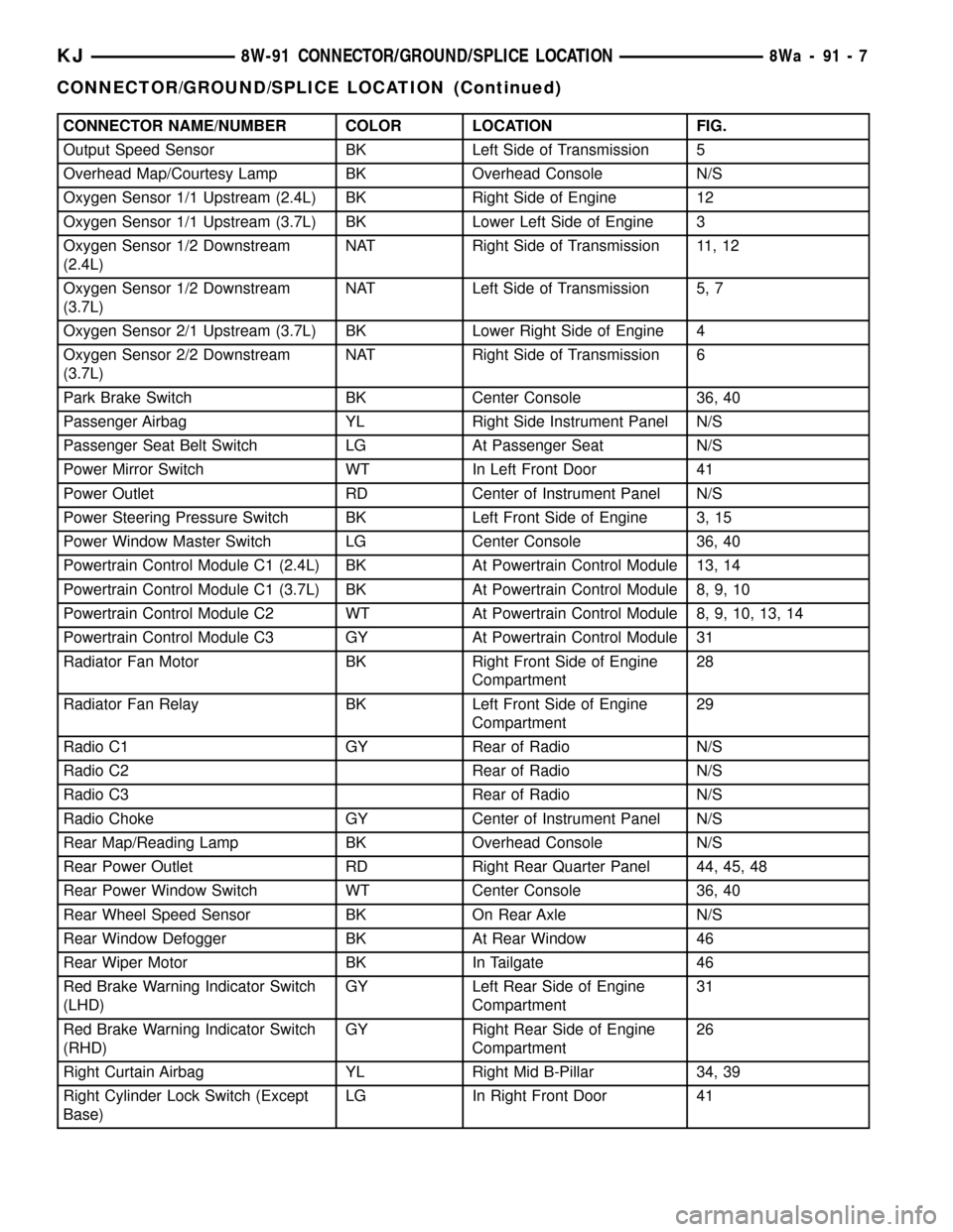
CONNECTOR NAME/NUMBER COLOR LOCATION FIG.
Output Speed Sensor BK Left Side of Transmission 5
Overhead Map/Courtesy Lamp BK Overhead Console N/S
Oxygen Sensor 1/1 Upstream (2.4L) BK Right Side of Engine 12
Oxygen Sensor 1/1 Upstream (3.7L) BK Lower Left Side of Engine 3
Oxygen Sensor 1/2 Downstream
(2.4L)NAT Right Side of Transmission 11, 12
Oxygen Sensor 1/2 Downstream
(3.7L)NAT Left Side of Transmission 5, 7
Oxygen Sensor 2/1 Upstream (3.7L) BK Lower Right Side of Engine 4
Oxygen Sensor 2/2 Downstream
(3.7L)NAT Right Side of Transmission 6
Park Brake Switch BK Center Console 36, 40
Passenger Airbag YL Right Side Instrument Panel N/S
Passenger Seat Belt Switch LG At Passenger Seat N/S
Power Mirror Switch WT In Left Front Door 41
Power Outlet RD Center of Instrument Panel N/S
Power Steering Pressure Switch BK Left Front Side of Engine 3, 15
Power Window Master Switch LG Center Console 36, 40
Powertrain Control Module C1 (2.4L) BK At Powertrain Control Module 13, 14
Powertrain Control Module C1 (3.7L) BK At Powertrain Control Module 8, 9, 10
Powertrain Control Module C2 WT At Powertrain Control Module 8, 9, 10, 13, 14
Powertrain Control Module C3 GY At Powertrain Control Module 31
Radiator Fan Motor BK Right Front Side of Engine
Compartment28
Radiator Fan Relay BK Left Front Side of Engine
Compartment29
Radio C1 GY Rear of Radio N/S
Radio C2 Rear of Radio N/S
Radio C3 Rear of Radio N/S
Radio Choke GY Center of Instrument Panel N/S
Rear Map/Reading Lamp BK Overhead Console N/S
Rear Power Outlet RD Right Rear Quarter Panel 44, 45, 48
Rear Power Window Switch WT Center Console 36, 40
Rear Wheel Speed Sensor BK On Rear Axle N/S
Rear Window Defogger BK At Rear Window 46
Rear Wiper Motor BK In Tailgate 46
Red Brake Warning Indicator Switch
(LHD)GY Left Rear Side of Engine
Compartment31
Red Brake Warning Indicator Switch
(RHD)GY Right Rear Side of Engine
Compartment26
Right Curtain Airbag YL Right Mid B-Pillar 34, 39
Right Cylinder Lock Switch (Except
Base)LG In Right Front Door 41
KJ8W-91 CONNECTOR/GROUND/SPLICE LOCATION8Wa-91-7
CONNECTOR/GROUND/SPLICE LOCATION (Continued)
Page 1163 of 1803
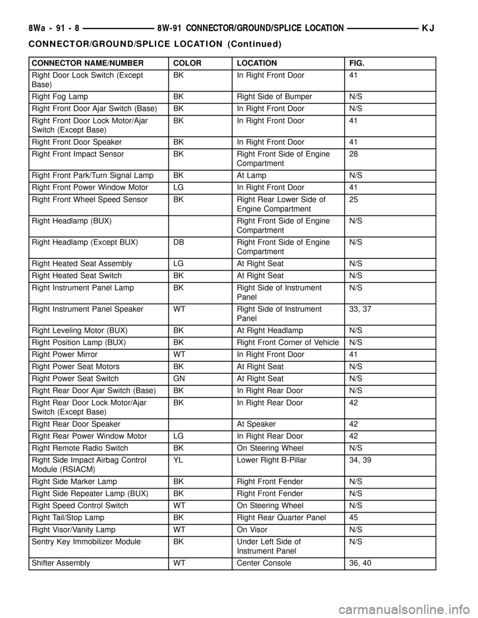
CONNECTOR NAME/NUMBER COLOR LOCATION FIG.
Right Door Lock Switch (Except
Base)BK In Right Front Door 41
Right Fog Lamp BK Right Side of Bumper N/S
Right Front Door Ajar Switch (Base) BK In Right Front Door N/S
Right Front Door Lock Motor/Ajar
Switch (Except Base)BK In Right Front Door 41
Right Front Door Speaker BK In Right Front Door 41
Right Front Impact Sensor BK Right Front Side of Engine
Compartment28
Right Front Park/Turn Signal Lamp BK At Lamp N/S
Right Front Power Window Motor LG In Right Front Door 41
Right Front Wheel Speed Sensor BK Right Rear Lower Side of
Engine Compartment25
Right Headlamp (BUX) Right Front Side of Engine
CompartmentN/S
Right Headlamp (Except BUX) DB Right Front Side of Engine
CompartmentN/S
Right Heated Seat Assembly LG At Right Seat N/S
Right Heated Seat Switch BK At Right Seat N/S
Right Instrument Panel Lamp BK Right Side of Instrument
PanelN/S
Right Instrument Panel Speaker WT Right Side of Instrument
Panel33, 37
Right Leveling Motor (BUX) BK At Right Headlamp N/S
Right Position Lamp (BUX) BK Right Front Corner of Vehicle N/S
Right Power Mirror WT In Right Front Door 41
Right Power Seat Motors BK At Right Seat N/S
Right Power Seat Switch GN At Right Seat N/S
Right Rear Door Ajar Switch (Base) BK In Right Rear Door N/S
Right Rear Door Lock Motor/Ajar
Switch (Except Base)BK In Right Rear Door 42
Right Rear Door Speaker At Speaker 42
Right Rear Power Window Motor LG In Right Rear Door 42
Right Remote Radio Switch BK On Steering Wheel N/S
Right Side Impact Airbag Control
Module (RSIACM)YL Lower Right B-Pillar 34, 39
Right Side Marker Lamp BK Right Front Fender N/S
Right Side Repeater Lamp (BUX) BK Right Front Fender N/S
Right Speed Control Switch WT On Steering Wheel N/S
Right Tail/Stop Lamp BK Right Rear Quarter Panel 45
Right Visor/Vanity Lamp WT On Visor N/S
Sentry Key Immobilizer Module BK Under Left Side of
Instrument PanelN/S
Shifter Assembly WT Center Console 36, 40
8Wa - 91 - 8 8W-91 CONNECTOR/GROUND/SPLICE LOCATIONKJ
CONNECTOR/GROUND/SPLICE LOCATION (Continued)
Page 1165 of 1803
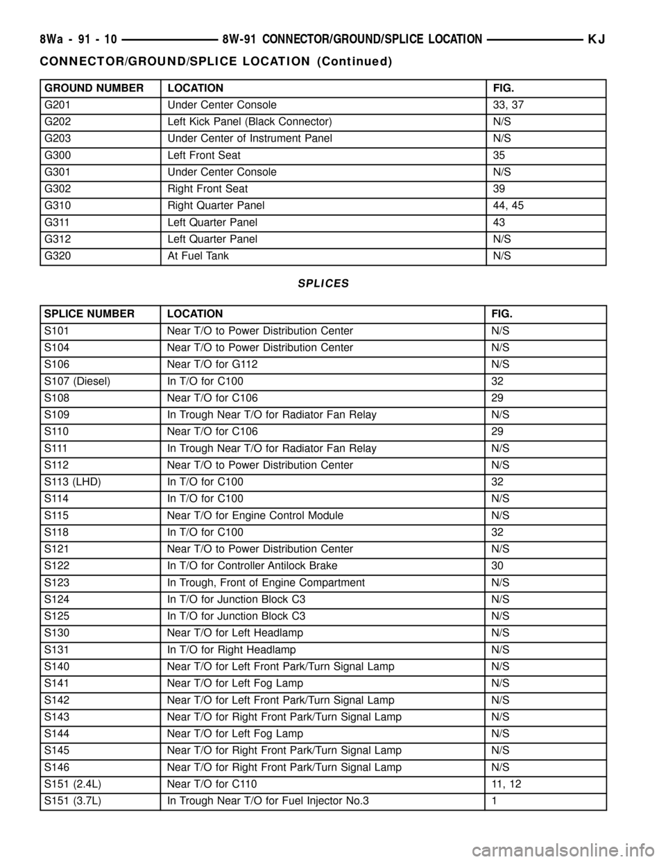
GROUND NUMBER LOCATION FIG.
G201 Under Center Console 33, 37
G202 Left Kick Panel (Black Connector) N/S
G203 Under Center of Instrument Panel N/S
G300 Left Front Seat 35
G301 Under Center Console N/S
G302 Right Front Seat 39
G310 Right Quarter Panel 44, 45
G311 Left Quarter Panel 43
G312 Left Quarter Panel N/S
G320 At Fuel Tank N/S
SPLICES
SPLICE NUMBER LOCATION FIG.
S101 Near T/O to Power Distribution Center N/S
S104 Near T/O to Power Distribution Center N/S
S106 Near T/O for G112 N/S
S107 (Diesel) In T/O for C100 32
S108 Near T/O for C106 29
S109 In Trough Near T/O for Radiator Fan Relay N/S
S110 Near T/O for C106 29
S111 In Trough Near T/O for Radiator Fan Relay N/S
S112 Near T/O to Power Distribution Center N/S
S113 (LHD) In T/O for C100 32
S114 In T/O for C100 N/S
S115 Near T/O for Engine Control Module N/S
S118 In T/O for C100 32
S121 Near T/O to Power Distribution Center N/S
S122 In T/O for Controller Antilock Brake 30
S123 In Trough, Front of Engine Compartment N/S
S124 In T/O for Junction Block C3 N/S
S125 In T/O for Junction Block C3 N/S
S130 Near T/O for Left Headlamp N/S
S131 In T/O for Right Headlamp N/S
S140 Near T/O for Left Front Park/Turn Signal Lamp N/S
S141 Near T/O for Left Fog Lamp N/S
S142 Near T/O for Left Front Park/Turn Signal Lamp N/S
S143 Near T/O for Right Front Park/Turn Signal Lamp N/S
S144 Near T/O for Left Fog Lamp N/S
S145 Near T/O for Right Front Park/Turn Signal Lamp N/S
S146 Near T/O for Right Front Park/Turn Signal Lamp N/S
S151 (2.4L) Near T/O for C110 11, 12
S151 (3.7L) In Trough Near T/O for Fuel Injector No.3 1
8Wa - 91 - 10 8W-91 CONNECTOR/GROUND/SPLICE LOCATIONKJ
CONNECTOR/GROUND/SPLICE LOCATION (Continued)
Page 1167 of 1803
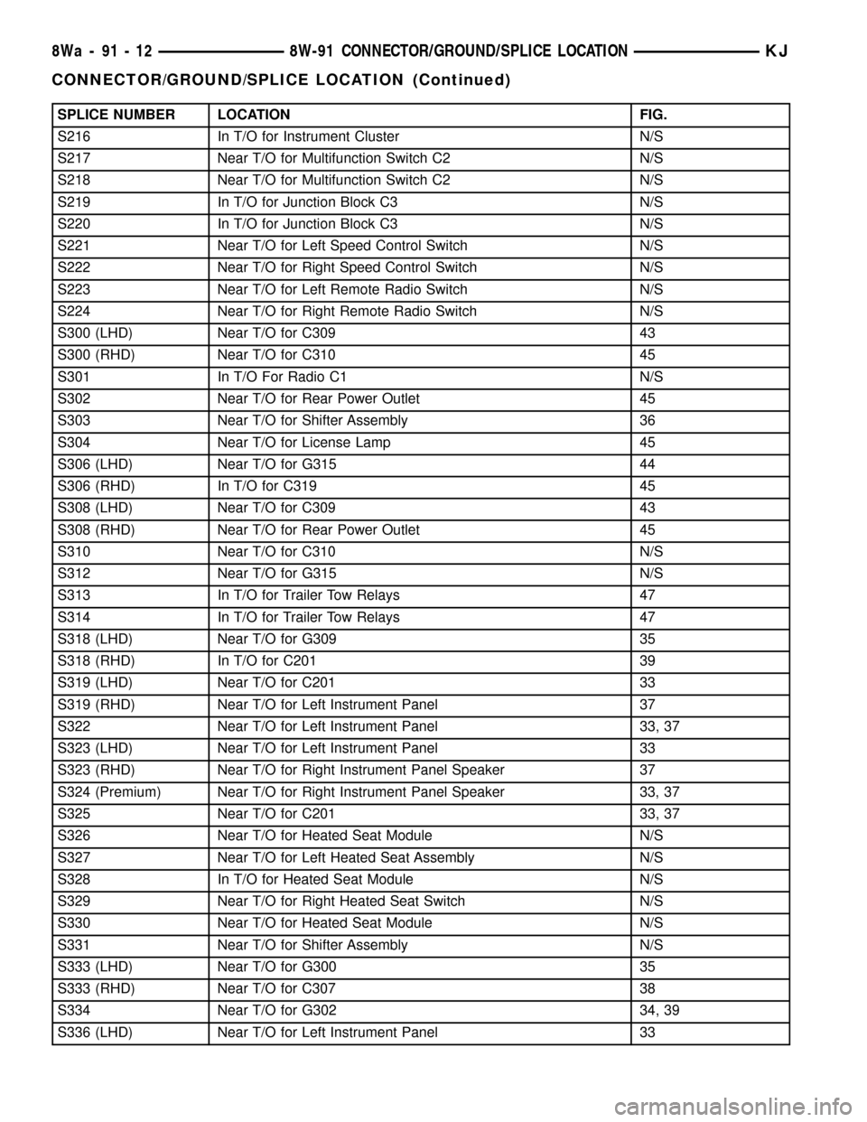
SPLICE NUMBER LOCATION FIG.
S216 In T/O for Instrument Cluster N/S
S217 Near T/O for Multifunction Switch C2 N/S
S218 Near T/O for Multifunction Switch C2 N/S
S219 In T/O for Junction Block C3 N/S
S220 In T/O for Junction Block C3 N/S
S221 Near T/O for Left Speed Control Switch N/S
S222 Near T/O for Right Speed Control Switch N/S
S223 Near T/O for Left Remote Radio Switch N/S
S224 Near T/O for Right Remote Radio Switch N/S
S300 (LHD) Near T/O for C309 43
S300 (RHD) Near T/O for C310 45
S301 In T/O For Radio C1 N/S
S302 Near T/O for Rear Power Outlet 45
S303 Near T/O for Shifter Assembly 36
S304 Near T/O for License Lamp 45
S306 (LHD) Near T/O for G315 44
S306 (RHD) In T/O for C319 45
S308 (LHD) Near T/O for C309 43
S308 (RHD) Near T/O for Rear Power Outlet 45
S310 Near T/O for C310 N/S
S312 Near T/O for G315 N/S
S313 In T/O for Trailer Tow Relays 47
S314 In T/O for Trailer Tow Relays 47
S318 (LHD) Near T/O for G309 35
S318 (RHD) In T/O for C201 39
S319 (LHD) Near T/O for C201 33
S319 (RHD) Near T/O for Left Instrument Panel 37
S322 Near T/O for Left Instrument Panel 33, 37
S323 (LHD) Near T/O for Left Instrument Panel 33
S323 (RHD) Near T/O for Right Instrument Panel Speaker 37
S324 (Premium) Near T/O for Right Instrument Panel Speaker 33, 37
S325 Near T/O for C201 33, 37
S326 Near T/O for Heated Seat Module N/S
S327 Near T/O for Left Heated Seat Assembly N/S
S328 In T/O for Heated Seat Module N/S
S329 Near T/O for Right Heated Seat Switch N/S
S330 Near T/O for Heated Seat Module N/S
S331 Near T/O for Shifter Assembly N/S
S333 (LHD) Near T/O for G300 35
S333 (RHD) Near T/O for C307 38
S334 Near T/O for G302 34, 39
S336 (LHD) Near T/O for Left Instrument Panel 33
8Wa - 91 - 12 8W-91 CONNECTOR/GROUND/SPLICE LOCATIONKJ
CONNECTOR/GROUND/SPLICE LOCATION (Continued)
Page 1224 of 1803
CYLINDER COMBUSTION PRESSURE LEAKAGE DIAGNOSIS CHART
CONDITION POSSIBLE CAUSE CORRECTION
AIR ESCAPES THROUGH
THROTTLE BODYIntake valve bent, burnt, or not
seated properlyInspect valve and valve seat.
Reface or replace, as necessary.
Inspect valve springs. Replace as
necessary.
AIR ESCAPES THROUGH
TAILPIPEExhaust valve bent, burnt, or not
seated properlyInspect valve and valve seat.
Reface or replace, as necessary.
Inspect valve springs. Replace as
necessary.
AIR ESCAPES THROUGH
RADIATORHead gasket leaking or cracked
cylinder head or blockRemove cylinder head and inspect.
Replace defective part
MORE THAN 50% LEAKAGE
FROM ADJACENT CYLINDERSHead gasket leaking or crack in
cylinder head or block between
adjacent cylindersRemove cylinder head and inspect.
Replace gasket, head, or block as
necessary
MORE THAN 25% LEAKAGE AND
AIR ESCAPES THROUGH OIL
FILLER CAP OPENING ONLYStuck or broken piston rings;
cracked piston; worn rings and/or
cylinder wallInspect for broken rings or piston.
Measure ring gap and cylinder
diameter, taper and out-of-round.
Replace defective part as necessary
STANDARD PROCEDURE
STANDARD PROCEDURE - ENGINE GASKET
SURFACE PREPARATION
To ensure engine gasket sealing, proper surface
preparation must be performed, especially with the
use of aluminum engine components and multi-layer
steel cylinder head gaskets.
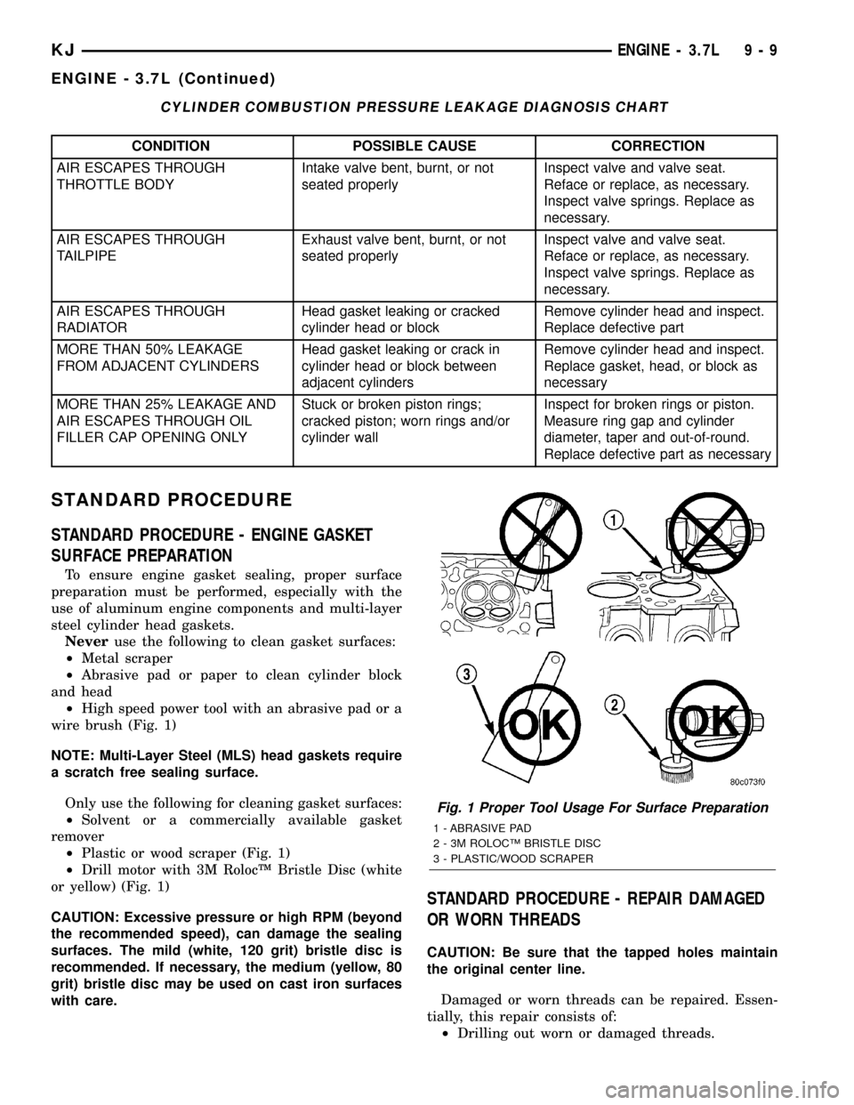
Neveruse the following to clean gasket surfaces:
²Metal scraper
²Abrasive pad or paper to clean cylinder block
and head
²High speed power tool with an abrasive pad or a
wire brush (Fig. 1)
NOTE: Multi-Layer Steel (MLS) head gaskets require
a scratch free sealing surface.
Only use the following for cleaning gasket surfaces:
²Solvent or a commercially available gasket
remover
²Plastic or wood scraper (Fig. 1)
²Drill motor with 3M RolocŸ Bristle Disc (white
or yellow) (Fig. 1)
CAUTION: Excessive pressure or high RPM (beyond
the recommended speed), can damage the sealing
surfaces. The mild (white, 120 grit) bristle disc is
recommended. If necessary, the medium (yellow, 80
grit) bristle disc may be used on cast iron surfaces
with care.
STANDARD PROCEDURE - REPAIR DAMAGED
OR WORN THREADS
CAUTION: Be sure that the tapped holes maintain
the original center line.
Damaged or worn threads can be repaired. Essen-
tially, this repair consists of:
²Drilling out worn or damaged threads.
Fig. 1 Proper Tool Usage For Surface Preparation
1 - ABRASIVE PAD
2 - 3M ROLOCŸ BRISTLE DISC
3 - PLASTIC/WOOD SCRAPER
KJENGINE - 3.7L 9 - 9
ENGINE - 3.7L (Continued)
Page 1292 of 1803
IDLER SHAFT
REMOVAL
(1) Remove the primary and secondary timing
chains and sprockets. Refer to procedure in this sec-
tion.
NOTE: To remove the idler shaft, it is necessary to
tap threads into the shaft, to install the removal
tool.
(2) Using a 12 mm X 1.75 tap, cut threads in the
idler shaft center bore.
(3) Cover the radiator core with a suitable cover.
CAUTION: Use care when removing the idler shaft,
Do not strike the radiator cooling fins with the slide
hammer.
(4) Using Special Tool 8517 Slide Hammer, remove
the idler shaft.
INSTALLATION
(1) Thoroughly clean the idler shaft bore.
(2) Position the idler shaft in the bore.
NOTE: The two lubrication holes in the idler shaft
do not require any special alignment.
NOTE: Before using the retaining bolt to install the
idler shaft, coat the threads and the pilot on the
idler shaft, with clean engine oil.
(3) Using the primary idler sprocket retaining bolt
and washer, carefully draw the idler shaft into the
bore until fully seated.
(4) Coat the idler shaft with clean engine oil.
(5) Install the timing chains and sprockets. Refer
to procedure in this section.
TIMING BELT/CHAIN AND
SPROCKET(S
REMOVAL
(1) Disconnect negative cable from battery.
(2) Drain cooling system. Refer to COOLING SYS-
TEM for procedures.
(3) Remove right and left cylinder head covers.
Refer to CYLINDER HEAD COVER.
(4) Remove radiator fan shroud. Refer to COOL-
ING SYSTEM for procedure.
(5) Rotate engine until timing mark on crankshaft
damper aligns with TDC mark on timing chain cover
(Fig. 103) (#1 cylinder exhaust stroke) and the cam-
shaft sprocket ªV6º marks are at the 12 o'clock posi-
tion (Fig. 102).
CAUTION: The nut on the right side camshaft
sprocket should not be removed for any reason, as
the sprocket and camshaft sensor target wheel is
serviced as an assembly. If the nut was removed
retorque nut to 5 N´m (44 in. lbs.).
(6) Remove power steering pump. Refer to STEER-
ING for procedure.
(7) Remove access plug from left and right cylinder
heads for access to chain guide fasteners (Fig. 104).
(8) Remove the oil fill housing to gain access to the
right side tensioner arm fastener.
(9) Remove crankshaft damper and timing chain
cover. Refer to procedures.
(10) Collapse and pin primary chain tensioner.
CAUTION: Plate behind left secondary chain ten-
sioner could fall into oil pan. Therefore, cover pan
opening.
(11) Remove secondary chain tensioners.
(12) Remove camshaft position and crankshaft
position sensors (Fig. 105) and (Fig. 106).
KJENGINE - 3.7L 9 - 77
Page 1316 of 1803
AIR CLEANER ELEMENT
REMOVAL - 2.4L
Housing removal is not necessary for element (fil-
ter) replacement.
(1) Disconnect air intake duct at side of element
cover.
(2) Pry up 2 spring clips from front of housing
cover (spring clips retain cover to housing).
(3) Release housing cover from locating tabs
located on rear of housing, and remove cover.
(4) Remove air cleaner element (filter) from hous-
ing.
(5) Clean inside of housing before replacing ele-
ment.
INSTALLATION - 2.4L
(1) Install element into housing.
(2) Position housing cover into housing locating
tabs.
(3) Pry up spring clips and lock cover to housing.
(4) Connect air intake duct.
If any air filter, air resonator, air intake tubes or
air filter housing clamps had been loosened or
removed, tighten them to 5 N´m (40 in. lbs.) torque.
CYLINDER HEAD
DESCRIPTION
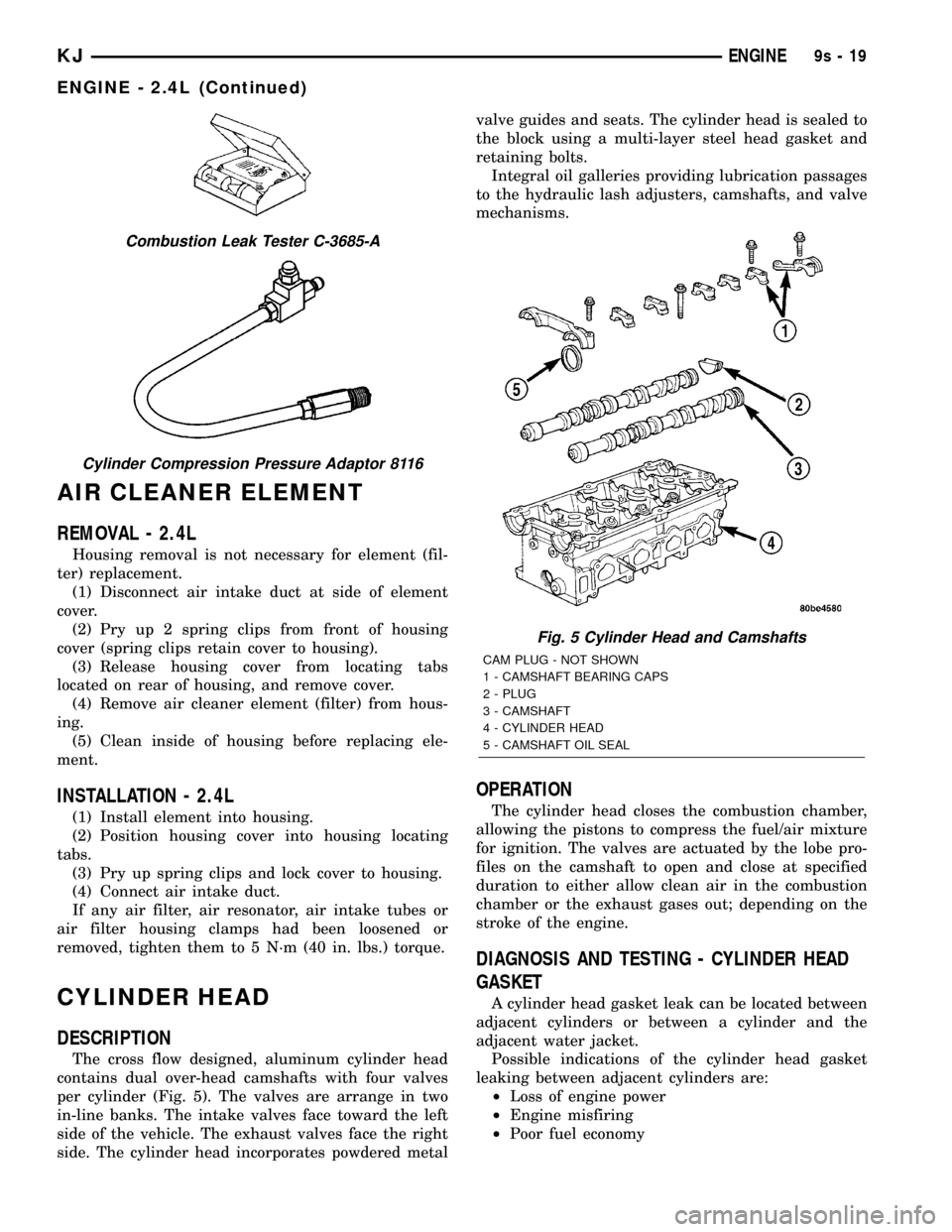
The cross flow designed, aluminum cylinder head
contains dual over-head camshafts with four valves
per cylinder (Fig. 5). The valves are arrange in two
in-line banks. The intake valves face toward the left
side of the vehicle. The exhaust valves face the right
side. The cylinder head incorporates powdered metalvalve guides and seats. The cylinder head is sealed to
the block using a multi-layer steel head gasket and
retaining bolts.
Integral oil galleries providing lubrication passages
to the hydraulic lash adjusters, camshafts, and valve
mechanisms.
OPERATION
The cylinder head closes the combustion chamber,
allowing the pistons to compress the fuel/air mixture
for ignition. The valves are actuated by the lobe pro-
files on the camshaft to open and close at specified
duration to either allow clean air in the combustion
chamber or the exhaust gases out; depending on the
stroke of the engine.
DIAGNOSIS AND TESTING - CYLINDER HEAD
GASKET
A cylinder head gasket leak can be located between
adjacent cylinders or between a cylinder and the
adjacent water jacket.
Possible indications of the cylinder head gasket
leaking between adjacent cylinders are:
²Loss of engine power
²Engine misfiring
²Poor fuel economy
Combustion Leak Tester C-3685-A
Cylinder Compression Pressure Adaptor 8116
Fig. 5 Cylinder Head and Camshafts
CAM PLUG - NOT SHOWN
1 - CAMSHAFT BEARING CAPS
2 - PLUG
3 - CAMSHAFT
4 - CYLINDER HEAD
5 - CAMSHAFT OIL SEAL
KJENGINE9s-19
ENGINE - 2.4L (Continued)