Transmission control module JEEP LIBERTY 2002 KJ / 1.G Repair Manual
[x] Cancel search | Manufacturer: JEEP, Model Year: 2002, Model line: LIBERTY, Model: JEEP LIBERTY 2002 KJ / 1.GPages: 1803, PDF Size: 62.3 MB
Page 1154 of 1803
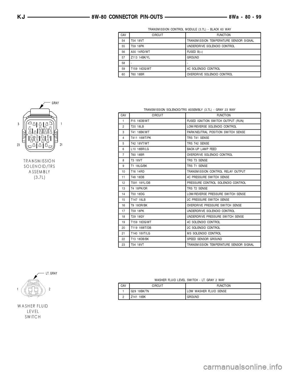
TRANSMISSION CONTROL MODULE (3.7L) - BLACK 60 WAY
CAV CIRCUIT FUNCTION
54 T54 18VT TRANSMISSION TEMPERATURE SENSOR SIGNAL
55 T59 18PK UNDERDRIVE SOLENOID CONTROL
56 A30 14RD/WT FUSED B(+)
57 Z113 14BK/YL GROUND
58 - -
59 T159 18DG/WT 4C SOLENOID CONTROL
60 T60 18BR OVERDRIVE SOLENOID CONTROL
TRANSMISSION SOLENOID/TRS ASSEMBLY (3.7L) - GRAY 23 WAY
CAV CIRCUIT FUNCTION
1 F15 18DB/WT FUSED IGNITION SWITCH OUTPUT (RUN)
2 T20 18LB LOW/REVERSE SOLENOID CONTROL
3 T41 18BK/WT PARK/NEUTRAL POSITION SWITCH SENSE
4 T411 18WT/PK TRS T41 SENSE
5 T42 18VT/WT TRS T42 SENSE
6 L10 18BR/LG BACK-UP LAMP FEED
7 T60 18BR OVERDRIVE SOLENOID CONTROL
8 T3 18VT TRS T3 SENSE
9 T1 18LG/BK TRS T1 SENSE
10 T16 14RD TRANSMISSION CONTROL RELAY OUTPUT
11 T48 18DB 4C PRESSURE SWITCH SENSE
12 T591 18YL/DB PRESSURE CONTROL SOLENOID CONTROL
13 T4 18PK/OR TRS T2 SENSE
14 T50 18DG LOW/REVERSE PRESSURE SWITCH SENSE
15 T147 18LB 2C PRESSURE SWITCH SENSE
16 T9 18OR/BK OVERDRIVE PRESSURE SWITCH SENSE
17 T59 18PK UNDERDRIVE SOLENOID CONTROL
18 T29 18GY UNDERDRIVE PRESSURE SWITCH SENSE
19 T159 18DG/WT 4C SOLENOID CONTROL
20 T119 18WT/DB 2C SOLENOID CONTROL
21 T140 18VT/LG MS SOLENOID CONTROL
22 T13 18DB/BK SPEED SENSOR GROUND
23 T54 18VT TRANSMISSION TEMPERATURE SENSOR SIGNAL
WASHER FLUID LEVEL SWITCH - LT. GRAY 2 WAY
CAV CIRCUIT FUNCTION
1 G29 18BK/TN LOW WASHER FLUID SENSE
2 Z141 18BK GROUND
KJ8W-80 CONNECTOR PIN-OUTS8Wa-80-99
Page 1156 of 1803
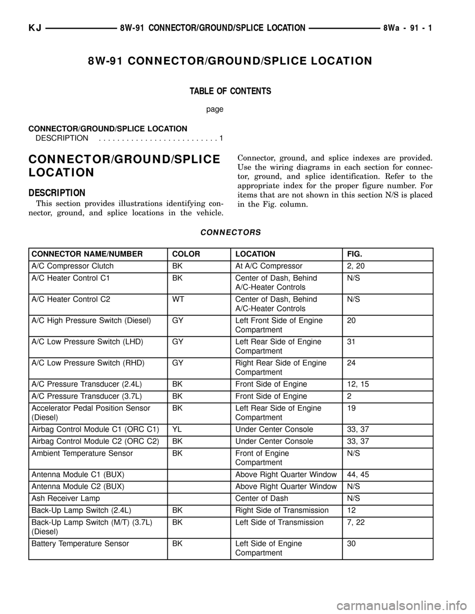
8W-91 CONNECTOR/GROUND/SPLICE LOCATION
TABLE OF CONTENTS
page
CONNECTOR/GROUND/SPLICE LOCATION
DESCRIPTION..........................1
CONNECTOR/GROUND/SPLICE
LOCATION
DESCRIPTION
This section provides illustrations identifying con-
nector, ground, and splice locations in the vehicle.Connector, ground, and splice indexes are provided.
Use the wiring diagrams in each section for connec-
tor, ground, and splice identification. Refer to the
appropriate index for the proper figure number. For
items that are not shown in this section N/S is placed
in the Fig. column.
CONNECTORS
CONNECTOR NAME/NUMBER COLOR LOCATION FIG.
A/C Compressor Clutch BK At A/C Compressor 2, 20
A/C Heater Control C1 BK Center of Dash, Behind
A/C-Heater ControlsN/S
A/C Heater Control C2 WT Center of Dash, Behind
A/C-Heater ControlsN/S
A/C High Pressure Switch (Diesel) GY Left Front Side of Engine
Compartment20
A/C Low Pressure Switch (LHD) GY Left Rear Side of Engine
Compartment31
A/C Low Pressure Switch (RHD) GY Right Rear Side of Engine
Compartment24
A/C Pressure Transducer (2.4L) BK Front Side of Engine 12, 15
A/C Pressure Transducer (3.7L) BK Front Side of Engine 2
Accelerator Pedal Position Sensor
(Diesel)BK Left Rear Side of Engine
Compartment19
Airbag Control Module C1 (ORC C1) YL Under Center Console 33, 37
Airbag Control Module C2 (ORC C2) BK Under Center Console 33, 37
Ambient Temperature Sensor BK Front of Engine
CompartmentN/S
Antenna Module C1 (BUX) Above Right Quarter Window 44, 45
Antenna Module C2 (BUX) Above Right Quarter Window N/S
Ash Receiver Lamp Center of Dash N/S
Back-Up Lamp Switch (2.4L) BK Right Side of Transmission 12
Back-Up Lamp Switch (M/T) (3.7L)
(Diesel)BK Left Side of Transmission 7, 22
Battery Temperature Sensor BK Left Side of Engine
Compartment30
KJ8W-91 CONNECTOR/GROUND/SPLICE LOCATION8Wa-91-1
Page 1160 of 1803
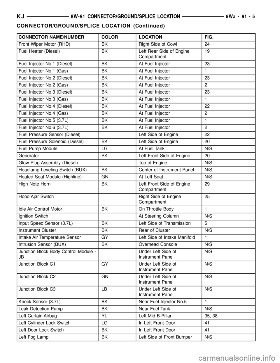
CONNECTOR NAME/NUMBER COLOR LOCATION FIG.
Front Wiper Motor (RHD) BK Right Side of Cowl 24
Fuel Heater (Diesel) BK Left Rear Side of Engine
Compartment19
Fuel Injector No.1 (Diesel) BK At Fuel Injector 23
Fuel Injector No.1 (Gas) BK At Fuel Injector 1
Fuel Injector No.2 (Diesel) BK At Fuel Injector 23
Fuel Injector No.2 (Gas) BK At Fuel Injector 2
Fuel Injector No.3 (Diesel) BK At Fuel Injector 23
Fuel Injector No.3 (Gas) BK At Fuel Injector 1
Fuel Injector No.4 (Diesel) BK At Fuel Injector 22
Fuel Injector No.4 (Gas) BK At Fuel Injector 2
Fuel Injector No.5 (3.7L) BK At Fuel Injector 1
Fuel Injector No.6 (3.7L) BK At Fuel Injector 2
Fuel Pressure Sensor (Diesel) Left Side of Engine 22
Fuel Pressure Solenoid (Diesel) BK Left Side of Engine 20
Fuel Pump Module LG At Fuel Tank N/S
Generator BK Left Front Side of Engine 20
Glow Plug Assembly (Diesel) Top of Engine N/S
Headlamp Leveling Switch (BUX) BK Center of Instrument Panel N/S
Heated Seat Module (Highline) GN At Left Seat N/S
High Note Horn BK Left Front Side of Engine
Compartment29
Hood Ajar Switch Right Side of Engine
Compartment25
Idle Air Control Motor BK On Throttle Body 1
Ignition Switch At Steering Column N/S
Input Speed Sensor (3.7L) BK Left Side of Transmission 5
Instrument Cluster BK Rear of Cluster N/S
Intake Air Temperature Sensor GY Left Side of Intake Manifold 1
Intrusion Sensor (BUX) BK Overhead Console N/S
Junction Block Body Control Module -
JBUnder Left Side of
Instrument PanelN/S
Junction Block C1 GY Under Left Side of
Instrument PanelN/S
Junction Block C2 GN Under Left Side of
Instrument PanelN/S
Junction Block C3 LB Under Left Side of
Instrument PanelN/S
Knock Sensor (3.7L) BK Near Fuel Injector No.5 1
Leak Detection Pump BK Near Fuel Tank N/S
Left Curtain Airbag YL Left Mid B-Pillar 35, 38
Left Cylinder Lock Switch LG In Left Front Door 41
Left Door Lock Switch BK In Left Front Door 41
Left Fog Lamp BK Left Side of Front Bumper N/S
KJ8W-91 CONNECTOR/GROUND/SPLICE LOCATION8Wa-91-5
CONNECTOR/GROUND/SPLICE LOCATION (Continued)
Page 1161 of 1803
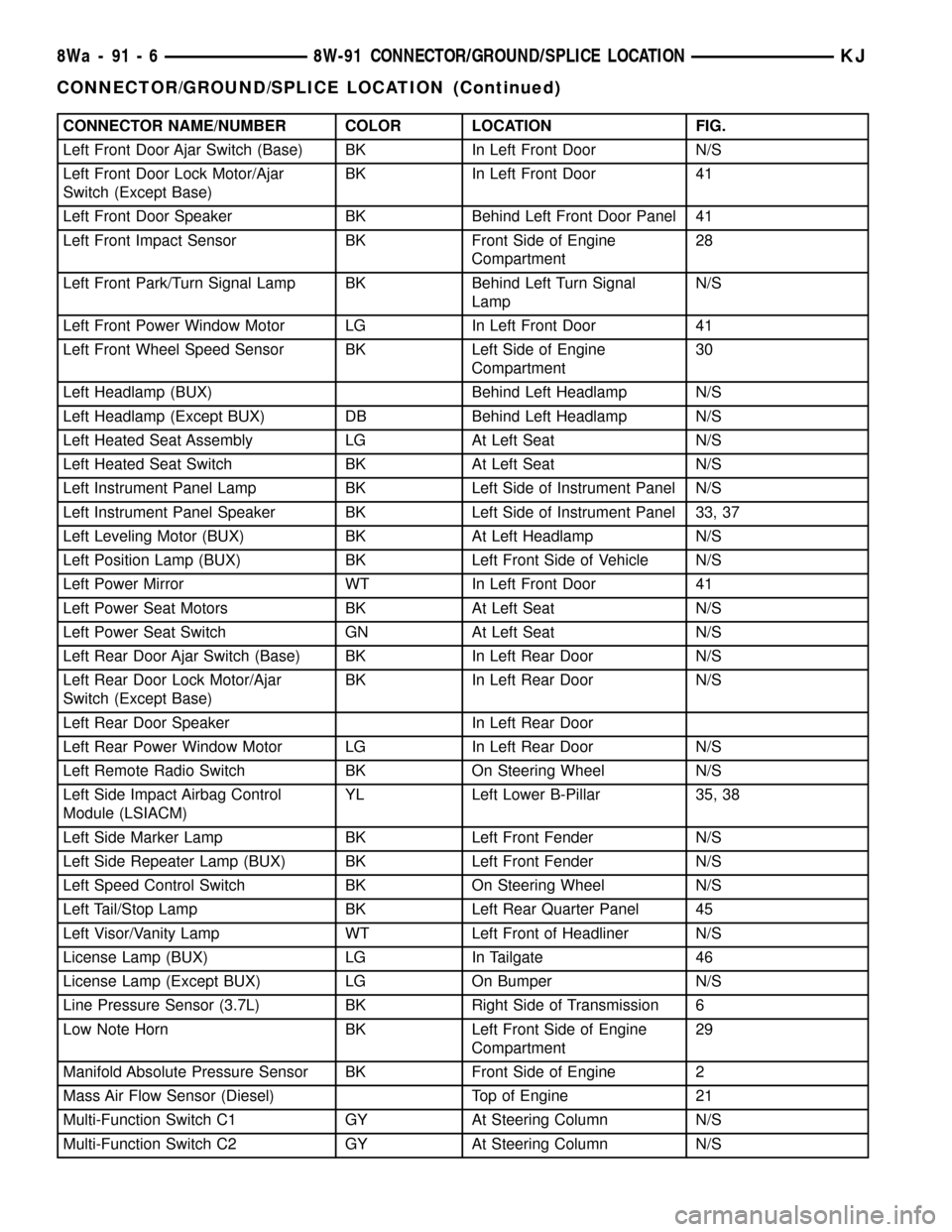
CONNECTOR NAME/NUMBER COLOR LOCATION FIG.
Left Front Door Ajar Switch (Base) BK In Left Front Door N/S
Left Front Door Lock Motor/Ajar
Switch (Except Base)BK In Left Front Door 41
Left Front Door Speaker BK Behind Left Front Door Panel 41
Left Front Impact Sensor BK Front Side of Engine
Compartment28
Left Front Park/Turn Signal Lamp BK Behind Left Turn Signal
LampN/S
Left Front Power Window Motor LG In Left Front Door 41
Left Front Wheel Speed Sensor BK Left Side of Engine
Compartment30
Left Headlamp (BUX) Behind Left Headlamp N/S
Left Headlamp (Except BUX) DB Behind Left Headlamp N/S
Left Heated Seat Assembly LG At Left Seat N/S
Left Heated Seat Switch BK At Left Seat N/S
Left Instrument Panel Lamp BK Left Side of Instrument Panel N/S
Left Instrument Panel Speaker BK Left Side of Instrument Panel 33, 37
Left Leveling Motor (BUX) BK At Left Headlamp N/S
Left Position Lamp (BUX) BK Left Front Side of Vehicle N/S
Left Power Mirror WT In Left Front Door 41
Left Power Seat Motors BK At Left Seat N/S
Left Power Seat Switch GN At Left Seat N/S
Left Rear Door Ajar Switch (Base) BK In Left Rear Door N/S
Left Rear Door Lock Motor/Ajar
Switch (Except Base)BK In Left Rear Door N/S
Left Rear Door Speaker In Left Rear Door
Left Rear Power Window Motor LG In Left Rear Door N/S
Left Remote Radio Switch BK On Steering Wheel N/S
Left Side Impact Airbag Control
Module (LSIACM)YL Left Lower B-Pillar 35, 38
Left Side Marker Lamp BK Left Front Fender N/S
Left Side Repeater Lamp (BUX) BK Left Front Fender N/S
Left Speed Control Switch BK On Steering Wheel N/S
Left Tail/Stop Lamp BK Left Rear Quarter Panel 45
Left Visor/Vanity Lamp WT Left Front of Headliner N/S
License Lamp (BUX) LG In Tailgate 46
License Lamp (Except BUX) LG On Bumper N/S
Line Pressure Sensor (3.7L) BK Right Side of Transmission 6
Low Note Horn BK Left Front Side of Engine
Compartment29
Manifold Absolute Pressure Sensor BK Front Side of Engine 2
Mass Air Flow Sensor (Diesel) Top of Engine 21
Multi-Function Switch C1 GY At Steering Column N/S
Multi-Function Switch C2 GY At Steering Column N/S
8Wa - 91 - 6 8W-91 CONNECTOR/GROUND/SPLICE LOCATIONKJ
CONNECTOR/GROUND/SPLICE LOCATION (Continued)
Page 1162 of 1803
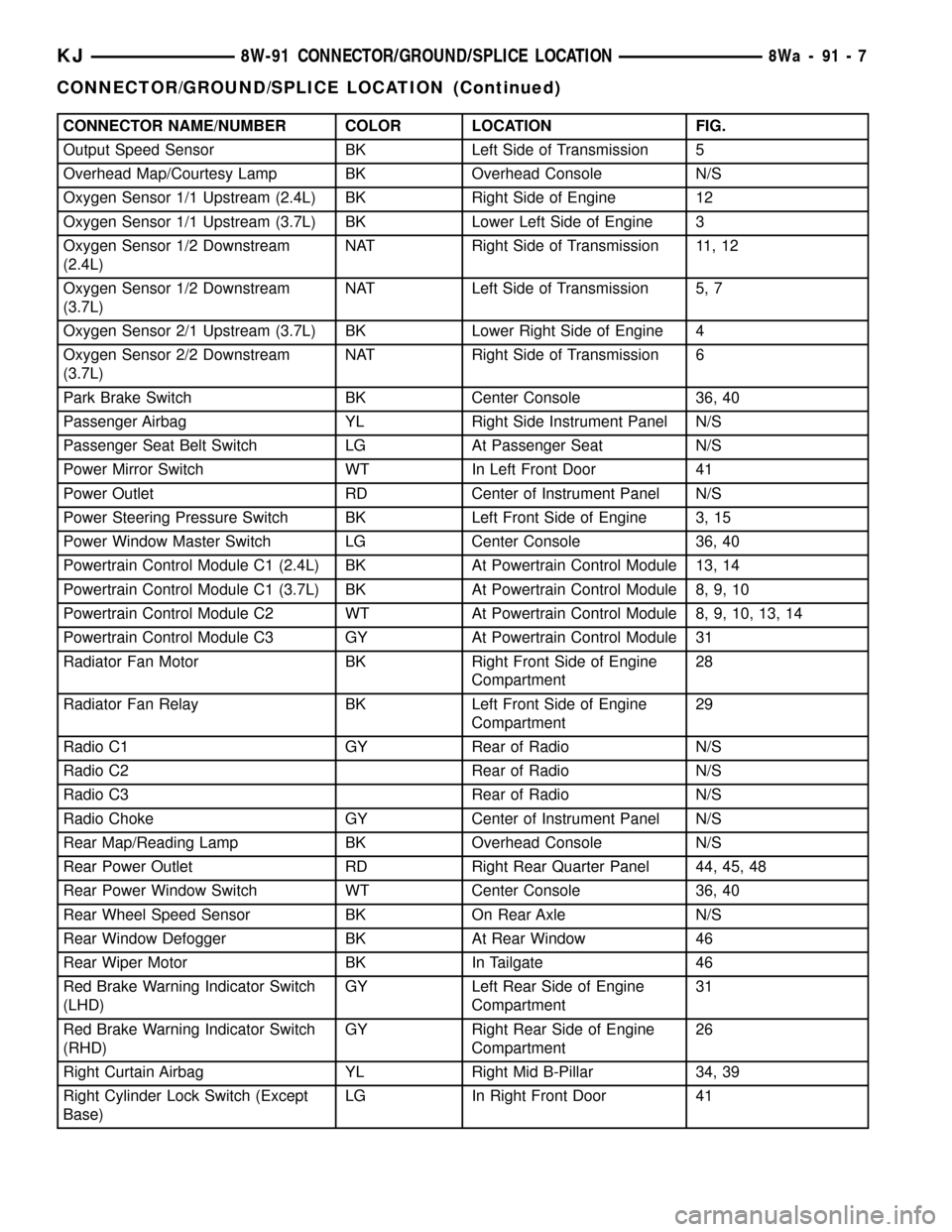
CONNECTOR NAME/NUMBER COLOR LOCATION FIG.
Output Speed Sensor BK Left Side of Transmission 5
Overhead Map/Courtesy Lamp BK Overhead Console N/S
Oxygen Sensor 1/1 Upstream (2.4L) BK Right Side of Engine 12
Oxygen Sensor 1/1 Upstream (3.7L) BK Lower Left Side of Engine 3
Oxygen Sensor 1/2 Downstream
(2.4L)NAT Right Side of Transmission 11, 12
Oxygen Sensor 1/2 Downstream
(3.7L)NAT Left Side of Transmission 5, 7
Oxygen Sensor 2/1 Upstream (3.7L) BK Lower Right Side of Engine 4
Oxygen Sensor 2/2 Downstream
(3.7L)NAT Right Side of Transmission 6
Park Brake Switch BK Center Console 36, 40
Passenger Airbag YL Right Side Instrument Panel N/S
Passenger Seat Belt Switch LG At Passenger Seat N/S
Power Mirror Switch WT In Left Front Door 41
Power Outlet RD Center of Instrument Panel N/S
Power Steering Pressure Switch BK Left Front Side of Engine 3, 15
Power Window Master Switch LG Center Console 36, 40
Powertrain Control Module C1 (2.4L) BK At Powertrain Control Module 13, 14
Powertrain Control Module C1 (3.7L) BK At Powertrain Control Module 8, 9, 10
Powertrain Control Module C2 WT At Powertrain Control Module 8, 9, 10, 13, 14
Powertrain Control Module C3 GY At Powertrain Control Module 31
Radiator Fan Motor BK Right Front Side of Engine
Compartment28
Radiator Fan Relay BK Left Front Side of Engine
Compartment29
Radio C1 GY Rear of Radio N/S
Radio C2 Rear of Radio N/S
Radio C3 Rear of Radio N/S
Radio Choke GY Center of Instrument Panel N/S
Rear Map/Reading Lamp BK Overhead Console N/S
Rear Power Outlet RD Right Rear Quarter Panel 44, 45, 48
Rear Power Window Switch WT Center Console 36, 40
Rear Wheel Speed Sensor BK On Rear Axle N/S
Rear Window Defogger BK At Rear Window 46
Rear Wiper Motor BK In Tailgate 46
Red Brake Warning Indicator Switch
(LHD)GY Left Rear Side of Engine
Compartment31
Red Brake Warning Indicator Switch
(RHD)GY Right Rear Side of Engine
Compartment26
Right Curtain Airbag YL Right Mid B-Pillar 34, 39
Right Cylinder Lock Switch (Except
Base)LG In Right Front Door 41
KJ8W-91 CONNECTOR/GROUND/SPLICE LOCATION8Wa-91-7
CONNECTOR/GROUND/SPLICE LOCATION (Continued)
Page 1164 of 1803
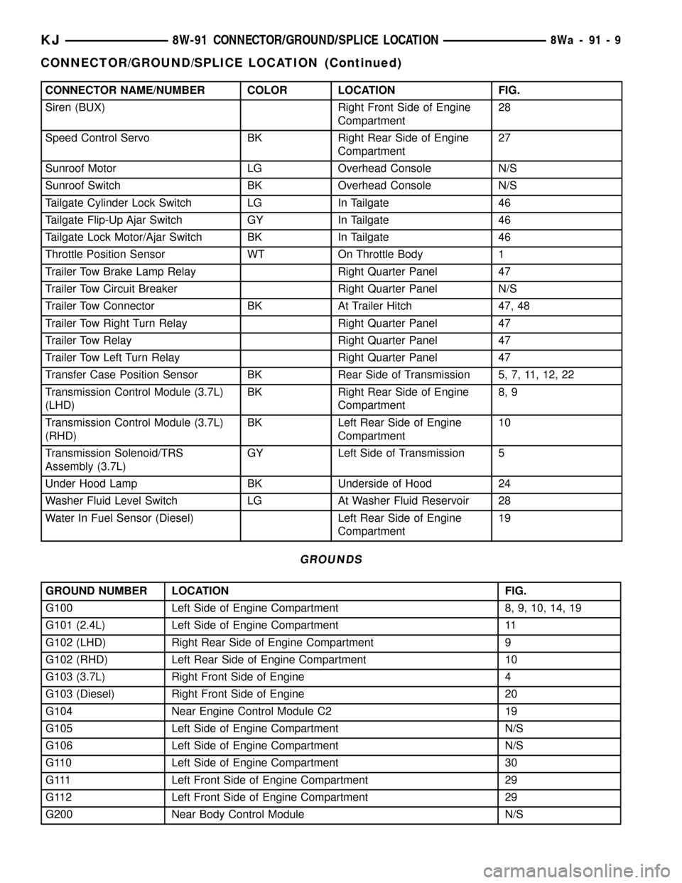
CONNECTOR NAME/NUMBER COLOR LOCATION FIG.
Siren (BUX) Right Front Side of Engine
Compartment28
Speed Control Servo BK Right Rear Side of Engine
Compartment27
Sunroof Motor LG Overhead Console N/S
Sunroof Switch BK Overhead Console N/S
Tailgate Cylinder Lock Switch LG In Tailgate 46
Tailgate Flip-Up Ajar Switch GY In Tailgate 46
Tailgate Lock Motor/Ajar Switch BK In Tailgate 46
Throttle Position Sensor WT On Throttle Body 1
Trailer Tow Brake Lamp Relay Right Quarter Panel 47
Trailer Tow Circuit Breaker Right Quarter Panel N/S
Trailer Tow Connector BK At Trailer Hitch 47, 48
Trailer Tow Right Turn Relay Right Quarter Panel 47
Trailer Tow Relay Right Quarter Panel 47
Trailer Tow Left Turn Relay Right Quarter Panel 47
Transfer Case Position Sensor BK Rear Side of Transmission 5, 7, 11, 12, 22
Transmission Control Module (3.7L)
(LHD)BK Right Rear Side of Engine
Compartment8, 9
Transmission Control Module (3.7L)
(RHD)BK Left Rear Side of Engine
Compartment10
Transmission Solenoid/TRS
Assembly (3.7L)GY Left Side of Transmission 5
Under Hood Lamp BK Underside of Hood 24
Washer Fluid Level Switch LG At Washer Fluid Reservoir 28
Water In Fuel Sensor (Diesel) Left Rear Side of Engine
Compartment19
GROUNDS
GROUND NUMBER LOCATION FIG.
G100 Left Side of Engine Compartment 8, 9, 10, 14, 19
G101 (2.4L) Left Side of Engine Compartment 11
G102 (LHD) Right Rear Side of Engine Compartment 9
G102 (RHD) Left Rear Side of Engine Compartment 10
G103 (3.7L) Right Front Side of Engine 4
G103 (Diesel) Right Front Side of Engine 20
G104 Near Engine Control Module C2 19
G105 Left Side of Engine Compartment N/S
G106 Left Side of Engine Compartment N/S
G110 Left Side of Engine Compartment 30
G111 Left Front Side of Engine Compartment 29
G112 Left Front Side of Engine Compartment 29
G200 Near Body Control Module N/S
KJ8W-91 CONNECTOR/GROUND/SPLICE LOCATION8Wa-91-9
CONNECTOR/GROUND/SPLICE LOCATION (Continued)
Page 1166 of 1803
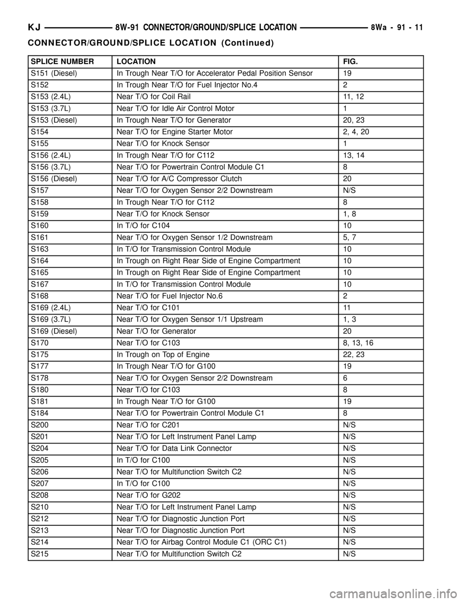
SPLICE NUMBER LOCATION FIG.
S151 (Diesel) In Trough Near T/O for Accelerator Pedal Position Sensor 19
S152 In Trough Near T/O for Fuel Injector No.4 2
S153 (2.4L) Near T/O for Coil Rail 11, 12
S153 (3.7L) Near T/O for Idle Air Control Motor 1
S153 (Diesel) In Trough Near T/O for Generator 20, 23
S154 Near T/O for Engine Starter Motor 2, 4, 20
S155 Near T/O for Knock Sensor 1
S156 (2.4L) In Trough Near T/O for C112 13, 14
S156 (3.7L) Near T/O for Powertrain Control Module C1 8
S156 (Diesel) Near T/O for A/C Compressor Clutch 20
S157 Near T/O for Oxygen Sensor 2/2 Downstream N/S
S158 In Trough Near T/O for C112 8
S159 Near T/O for Knock Sensor 1, 8
S160 In T/O for C104 10
S161 Near T/O for Oxygen Sensor 1/2 Downstream 5, 7
S163 In T/O for Transmission Control Module 10
S164 In Trough on Right Rear Side of Engine Compartment 10
S165 In Trough on Right Rear Side of Engine Compartment 10
S167 In T/O for Transmission Control Module 10
S168 Near T/O for Fuel Injector No.6 2
S169 (2.4L) Near T/O for C101 11
S169 (3.7L) Near T/O for Oxygen Sensor 1/1 Upstream 1, 3
S169 (Diesel) Near T/O for Generator 20
S170 Near T/O for C103 8, 13, 16
S175 In Trough on Top of Engine 22, 23
S177 In Trough Near T/O for G100 19
S178 Near T/O for Oxygen Sensor 2/2 Downstream 6
S180 Near T/O for C103 8
S181 In Trough Near T/O for G100 19
S184 Near T/O for Powertrain Control Module C1 8
S200 Near T/O for C201 N/S
S201 Near T/O for Left Instrument Panel Lamp N/S
S204 Near T/O for Data Link Connector N/S
S205 In T/O for C100 N/S
S206 Near T/O for Multifunction Switch C2 N/S
S207 In T/O for C100 N/S
S208 Near T/O for G202 N/S
S210 Near T/O for Left Instrument Panel Lamp N/S
S212 Near T/O for Diagnostic Junction Port N/S
S213 Near T/O for Diagnostic Junction Port N/S
S214 Near T/O for Airbag Control Module C1 (ORC C1) N/S
S215 Near T/O for Multifunction Switch C2 N/S
KJ8W-91 CONNECTOR/GROUND/SPLICE LOCATION8Wa-91-11
CONNECTOR/GROUND/SPLICE LOCATION (Continued)
Page 1425 of 1803

WARNING: THE EXHAUST MANIFOLD, EXHAUST
PIPES AND CATALYTIC CONVERTER BECOME
VERY HOT DURING ENGINE OPERATION. ALLOW
ENGINE TO COOL BEFORE REMOVING OXYGEN
SENSOR.
(1) Raise and support vehicle.
(2) Disconnect wire connector from O2S sensor.
CAUTION: When disconnecting sensor electrical
connector, do not pull directly on wire going into
sensor.
(3) Remove O2S sensor with an oxygen sensor
removal and installation tool.
(4) Clean threads in exhaust pipe using appropri-
ate tap.
INSTALLATION
Threads of new oxygen sensors are factory coated
with anti-seize compound to aid in removal.DO
NOT add any additional anti-seize compound to
threads of a new oxygen sensor.
(1) Install O2S sensor. Tighten to 30 N´m (22 ft.
lbs.) torque.
(2) Connect O2S sensor wire connector.
(3) Lower vehicle.
THROTTLE BODY
DESCRIPTION
The throttle body is located on the intake manifold.
Fuel does not enter the intake manifold through the
throttle body. Fuel is sprayed into the manifold by
the fuel injectors.
OPERATION
Filtered air from the air cleaner enters the intake
manifold through the throttle body. The throttle body
contains an air control passage controlled by an Idle
Air Control (IAC) motor. The air control passage is
used to supply air for idle conditions. A throttle valve
(plate) is used to supply air for above idle conditions.
Certain sensors are attached to the throttle body.
The accelerator pedal cable, speed control cable and
transmission control cable (when equipped) are con-
nected to the throttle body linkage arm.
A (factory adjusted) set screw is used to mechani-
cally limit the position of the throttle body throttle
plate.Never attempt to adjust the engine idle
speed using this screw.All idle speed functions are
controlled by the PCM.
REMOVAL
2.4L
A (factory adjusted) set screw is used to mechani-
cally limit the position of the throttle body throttle
plate.Never attempt to adjust the engine idle
speed using this screw.All idle speed functions are
controlled by the Powertrain Control Module (PCM).
(1) Remove air cleaner tube at throttle body.
(2) Disconnect throttle body electrical connectors
at IAC motor and TPS.
(3) Remove all control cables from throttle body
(lever) arm. Refer to the Accelerator Pedal and Throt-
tle Cable section for removal/installation procedures.
(4) Disconnect necessary vacuum lines at throttle
body.
(5) Remove 3 throttle body mounting bolts (Fig.
23).
(6) Remove throttle body from intake manifold.
(7) Check condition of old throttle body-to-intake
manifold o-ring.
3.7L
A (factory adjusted) set screw is used to mechani-
cally limit the position of the throttle body throttle
plate.Never attempt to adjust the engine idle
speed using this screw.All idle speed functions are
controlled by the Powertrain Control Module (PCM).
(1) Remove air cleaner tube at throttle body.
(2) Disconnect throttle body electrical connectors
at IAC motor and TPS.
Fig. 23 THROTTLE BODY MOUNTING BOLTS - 2.4L
1 - THROTTLE BODY
2 - IGNITION COIL
3 - MOUNTING BOLTS (3)
KJFUEL INJECTION 14 - 43
OXYGEN SENSOR (Continued)
Page 1715 of 1803
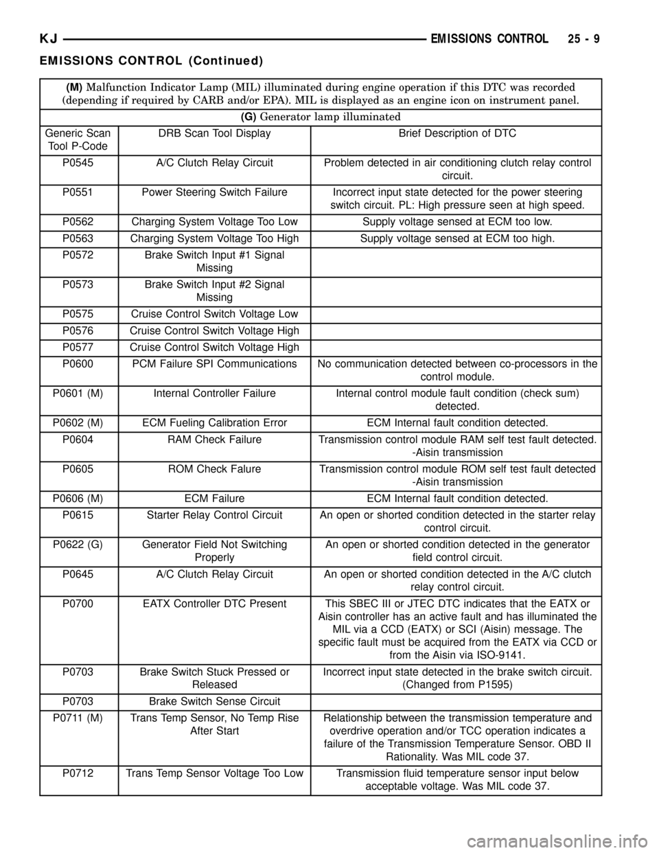
(M)Malfunction Indicator Lamp (MIL) illuminated during engine operation if this DTC was recorded
(depending if required by CARB and/or EPA). MIL is displayed as an engine icon on instrument panel.
(G)Generator lamp illuminated
Generic Scan
Tool P-CodeDRB Scan Tool Display Brief Description of DTC
P0545 A/C Clutch Relay Circuit Problem detected in air conditioning clutch relay control
circuit.
P0551 Power Steering Switch Failure Incorrect input state detected for the power steering
switch circuit. PL: High pressure seen at high speed.
P0562 Charging System Voltage Too Low Supply voltage sensed at ECM too low.
P0563 Charging System Voltage Too High Supply voltage sensed at ECM too high.
P0572 Brake Switch Input #1 Signal
Missing
P0573 Brake Switch Input #2 Signal
Missing
P0575 Cruise Control Switch Voltage Low
P0576 Cruise Control Switch Voltage High
P0577 Cruise Control Switch Voltage High
P0600 PCM Failure SPI Communications No communication detected between co-processors in the
control module.
P0601 (M) Internal Controller Failure Internal control module fault condition (check sum)
detected.
P0602 (M) ECM Fueling Calibration Error ECM Internal fault condition detected.
P0604 RAM Check Failure Transmission control module RAM self test fault detected.
-Aisin transmission
P0605 ROM Check Falure Transmission control module ROM self test fault detected
-Aisin transmission
P0606 (M) ECM Failure ECM Internal fault condition detected.
P0615 Starter Relay Control Circuit An open or shorted condition detected in the starter relay
control circuit.
P0622 (G) Generator Field Not Switching
ProperlyAn open or shorted condition detected in the generator
field control circuit.
P0645 A/C Clutch Relay Circuit An open or shorted condition detected in the A/C clutch
relay control circuit.
P0700 EATX Controller DTC Present This SBEC III or JTEC DTC indicates that the EATX or
Aisin controller has an active fault and has illuminated the
MIL via a CCD (EATX) or SCI (Aisin) message. The
specific fault must be acquired from the EATX via CCD or
from the Aisin via ISO-9141.
P0703 Brake Switch Stuck Pressed or
ReleasedIncorrect input state detected in the brake switch circuit.
(Changed from P1595)
P0703 Brake Switch Sense Circuit
P0711 (M) Trans Temp Sensor, No Temp Rise
After StartRelationship between the transmission temperature and
overdrive operation and/or TCC operation indicates a
failure of the Transmission Temperature Sensor. OBD II
Rationality. Was MIL code 37.
P0712 Trans Temp Sensor Voltage Too Low Transmission fluid temperature sensor input below
acceptable voltage. Was MIL code 37.
KJEMISSIONS CONTROL 25 - 9
EMISSIONS CONTROL (Continued)
Page 1721 of 1803
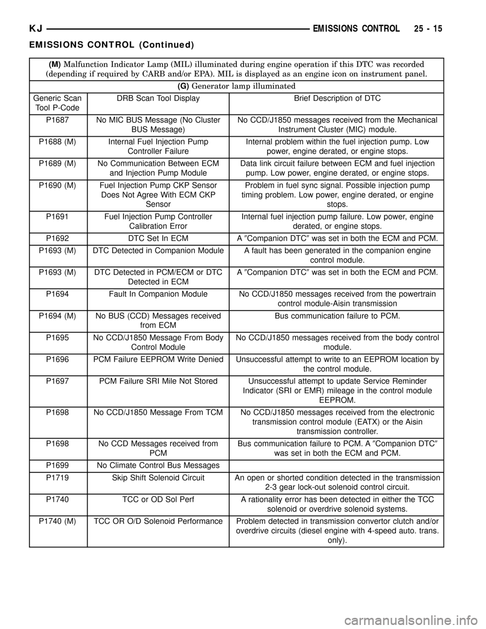
(M)Malfunction Indicator Lamp (MIL) illuminated during engine operation if this DTC was recorded
(depending if required by CARB and/or EPA). MIL is displayed as an engine icon on instrument panel.
(G)Generator lamp illuminated
Generic Scan
Tool P-CodeDRB Scan Tool Display Brief Description of DTC
P1687 No MIC BUS Message (No Cluster
BUS Message)No CCD/J1850 messages received from the Mechanical
Instrument Cluster (MIC) module.
P1688 (M) Internal Fuel Injection Pump
Controller FailureInternal problem within the fuel injection pump. Low
power, engine derated, or engine stops.
P1689 (M) No Communication Between ECM
and Injection Pump ModuleData link circuit failure between ECM and fuel injection
pump. Low power, engine derated, or engine stops.
P1690 (M) Fuel Injection Pump CKP Sensor
Does Not Agree With ECM CKP
SensorProblem in fuel sync signal. Possible injection pump
timing problem. Low power, engine derated, or engine
stops.
P1691 Fuel Injection Pump Controller
Calibration ErrorInternal fuel injection pump failure. Low power, engine
derated, or engine stops.
P1692 DTC Set In ECM A9Companion DTC9was set in both the ECM and PCM.
P1693 (M) DTC Detected in Companion Module A fault has been generated in the companion engine
control module.
P1693 (M) DTC Detected in PCM/ECM or DTC
Detected in ECMA9Companion DTC9was set in both the ECM and PCM.
P1694 Fault In Companion Module No CCD/J1850 messages received from the powertrain
control module-Aisin transmission
P1694 (M) No BUS (CCD) Messages received
from ECMBus communication failure to PCM.
P1695 No CCD/J1850 Message From Body
Control ModuleNo CCD/J1850 messages received from the body control
module.
P1696 PCM Failure EEPROM Write Denied Unsuccessful attempt to write to an EEPROM location by
the control module.
P1697 PCM Failure SRI Mile Not Stored Unsuccessful attempt to update Service Reminder
Indicator (SRI or EMR) mileage in the control module
EEPROM.
P1698 No CCD/J1850 Message From TCM No CCD/J1850 messages received from the electronic
transmission control module (EATX) or the Aisin
transmission controller.
P1698 No CCD Messages received from
PCMBus communication failure to PCM. A9Companion DTC9
was set in both the ECM and PCM.
P1699 No Climate Control Bus Messages
P1719 Skip Shift Solenoid Circuit An open or shorted condition detected in the transmission
2-3 gear lock-out solenoid control circuit.
P1740 TCC or OD Sol Perf A rationality error has been detected in either the TCC
solenoid or overdrive solenoid systems.
P1740 (M) TCC OR O/D Solenoid Performance Problem detected in transmission convertor clutch and/or
overdrive circuits (diesel engine with 4-speed auto. trans.
only).
KJEMISSIONS CONTROL 25 - 15
EMISSIONS CONTROL (Continued)