Bumper JEEP LIBERTY 2002 KJ / 1.G Workshop Manual
[x] Cancel search | Manufacturer: JEEP, Model Year: 2002, Model line: LIBERTY, Model: JEEP LIBERTY 2002 KJ / 1.GPages: 1803, PDF Size: 62.3 MB
Page 3 of 1803
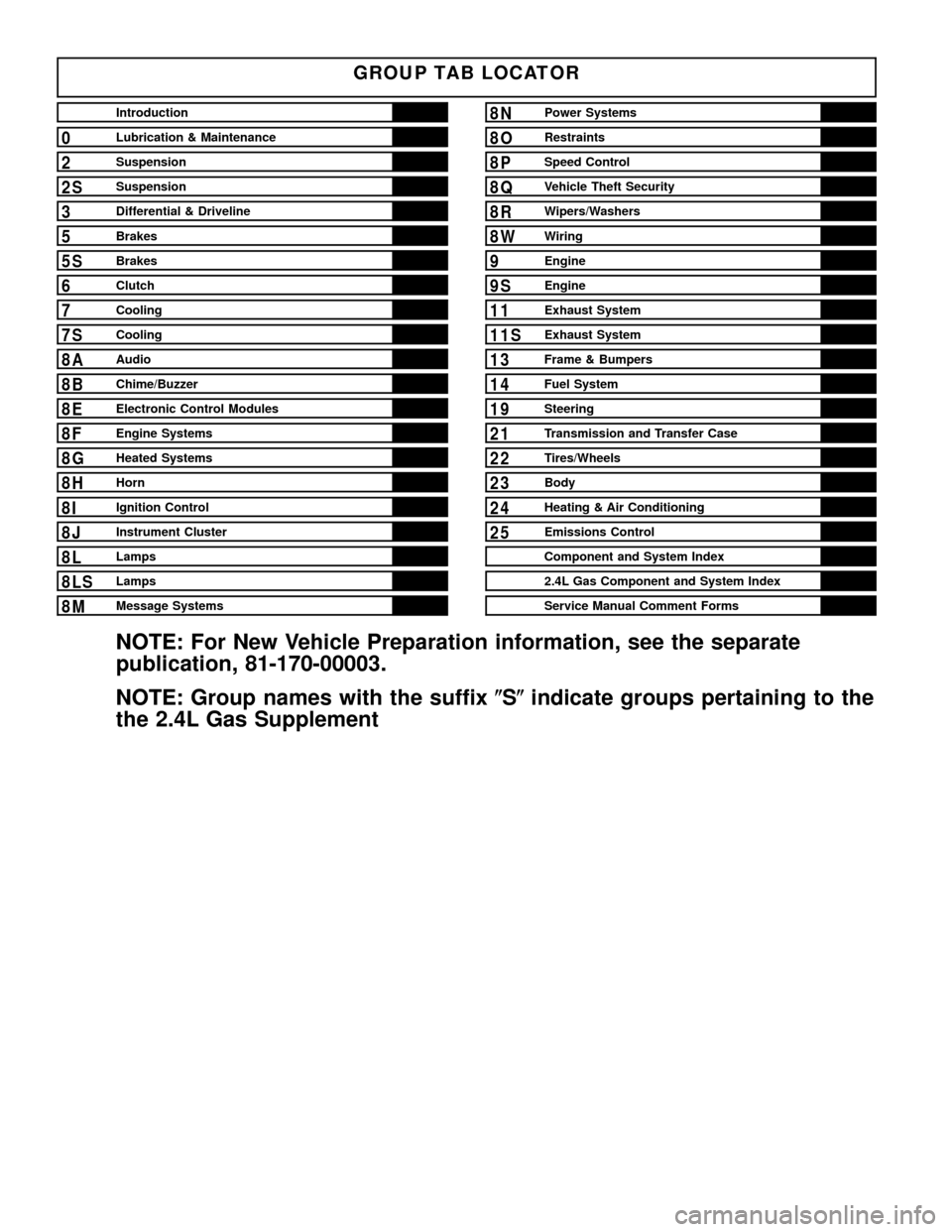
GROUP TAB LOCATOR
Introduction
0Lubrication & Maintenance
2Suspension
2SSuspension
3Differential & Driveline
5Brakes
5SBrakes
6Clutch
7Cooling
7SCooling
8AAudio
8BChime/Buzzer
8EElectronic Control Modules
8FEngine Systems
8GHeated Systems
8HHorn
8IIgnition Control
8JInstrument Cluster
8LLamps
8LSLamps
8MMessage Systems
8NPower Systems
8ORestraints
8PSpeed Control
8QVehicle Theft Security
8RWipers/Washers
8WWiring
9Engine
9SEngine
11Exhaust System
11SExhaust System
13Frame & Bumpers
14Fuel System
19Steering
21Transmission and Transfer Case
22Tires/Wheels
23Body
24Heating & Air Conditioning
25Emissions Control
Component and System Index
2.4L Gas Component and System Index
Service Manual Comment Forms
NOTE: For New Vehicle Preparation information, see the separate
publication, 81-170-00003.
NOTE: Group names with the suffix(S(indicate groups pertaining to the
the 2.4L Gas Supplement
Page 19 of 1803
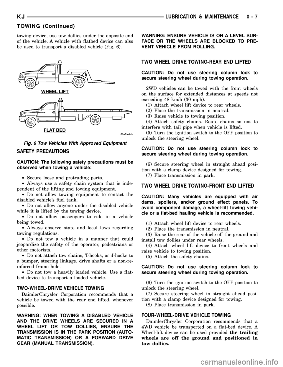
towing device, use tow dollies under the opposite end
of the vehicle. A vehicle with flatbed device can also
be used to transport a disabled vehicle (Fig. 6).
SAFETY PRECAUTIONS
CAUTION: The following safety precautions must be
observed when towing a vehicle:
²Secure loose and protruding parts.
²Always use a safety chain system that is inde-
pendent of the lifting and towing equipment.
²Do not allow towing equipment to contact the
disabled vehicle's fuel tank.
²Do not allow anyone under the disabled vehicle
while it is lifted by the towing device.
²Do not allow passengers to ride in a vehicle
being towed.
²Always observe state and local laws regarding
towing regulations.
²Do not tow a vehicle in a manner that could
jeopardize the safety of the operator, pedestrians or
other motorists.
²Do not attach tow chains, T-hooks, or J-hooks to
a bumper, steering linkage, drive shafts or a non-re-
inforced frame hole.
²Do not tow a heavily loaded vehicle. Use a flat-
bed device to transport a loaded vehicle.
TWO-WHEEL-DRIVE VEHICLE TOWING
DaimlerChrysler Corporation recommends that a
vehicle be towed with the rear end lifted, whenever
possible.
WARNING: WHEN TOWING A DISABLED VEHICLE
AND THE DRIVE WHEELS ARE SECURED IN A
WHEEL LIFT OR TOW DOLLIES, ENSURE THE
TRANSMISSION IS IN THE PARK POSITION (AUTO-
MATIC TRANSMISSION) OR A FORWARD DRIVE
GEAR (MANUAL TRANSMISSION).WARNING: ENSURE VEHICLE IS ON A LEVEL SUR-
FACE OR THE WHEELS ARE BLOCKED TO PRE-
VENT VEHICLE FROM ROLLING.
TWO WHEEL DRIVE TOWING-REAR END LIFTED
CAUTION: Do not use steering column lock to
secure steering wheel during towing operation.
2WD vehicles can be towed with the front wheels
on the surface for extended distances at speeds not
exceeding 48 km/h (30 mph).
(1) Attach wheel lift device to rear wheels.
(2) Place the transmission in neutral.
(3) Raise vehicle to towing position.
(4) Attach safety chains. Route chains so not to
interfere with tail pipe when vehicle is lifted.
(5) Turn the ignition switch to the OFF position to
unlock the steering wheel.
CAUTION: Do not use steering column lock to
secure steering wheel during towing operation.
(6) Secure steering wheel in straight ahead posi-
tion with a clamp device designed for towing.
(7) Place transmission in park.
TWO WHEEL DRIVE TOWING-FRONT END LIFTED
CAUTION: Many vehicles are equipped with air
dams, spoilers, and/or ground effect panels. To
avoid component damage, a wheel-lift towing vehi-
cle or a flat-bed hauling vehicle is recommended.
(1) Attach wheel lift device to rear wheels.
(2) Place the transmission in neutral.
(3) Raise the rear of the vehicle off the ground and
install tow dollies under rear wheels.
(4) Attach wheel lift device to front wheels and
raise vehicle to towing position.
(5) Attach the safety chains.
CAUTION: Do not use steering column lock to
secure steering wheel during towing operation.
(6) Turn the ignition switch to the OFF position to
unlock the steering wheel.
(7) Secure steering wheel in straight ahead posi-
tion with a clamp device designed for towing.
(8) Place transmission in park.
FOUR-WHEEL-DRIVE VEHICLE TOWING
DaimlerChrysler Corporation recommends that a
4WD vehicle be transported on a flat-bed device. A
Wheel-lift device can be used providedthe trailing
wheels are off the ground and positioned in
tow dollies.
Fig. 6 Tow Vehicles With Approved Equipment
KJLUBRICATION & MAINTENANCE 0 - 7
TOWING (Continued)
Page 31 of 1803
(5) Align the marks front and rear at the cam/
pivot bolts and tighten the bolts. Tighten the bolts to
170 N´m (125 ft.lbs.)
(6) Install the stabilizer link bolt at the lower con-
trol arm. Tighten the bolt to 136 N´m (100 ft.lbs.)
(7) Install the lower clevis bracket bolt at the
lower control arm. Tighten the bolt to 150 N´m (110
ft.lbs.)
(8) Install the tire and wheel assembly. (Refer to
22 - TIRES/WHEELS/WHEELS - STANDARD PRO-
CEDURE).
(9) Perform a full wheel alignment (Refer to 2 -
SUSPENSION/WHEEL ALIGNMENT - STANDARD
PROCEDURE).
SHOCK
REMOVAL
REMOVAL - LEFT SIDE
(1) Disconnect the battery.
(2) Remove the battery (Refer to 8 - ELECTRI-
CAL/BATTERY SYSTEM/BATTERY - REMOVAL).
(3) Unclip the power center and move it to the side
out of the way.
(4) Remove the battery tray (Refer to 8 - ELEC-
TRICAL/BATTERY SYSTEM/TRAY - REMOVAL).
(5) Disconnect the battery temperature sensor
from the battery tray.
(6) Remove the four upper shock mounting nuts.
(7) Raise and support the vehicle.(8) Remove the left tire and wheel assembly.
(9) Remove the lower bolt at the lower control
securing the clevis bracket.
(10) Remove the stabilizer link (Refer to 2 - SUS-
PENSION/FRONT/STABILIZER LINK - REMOVAL).
(11) Remove the lower ball joint nut.
(12) Seperate the lower ball joint from the lower
control arm using tool C-4150A.
(13) Rotate the lower control arm downward to
allow access.
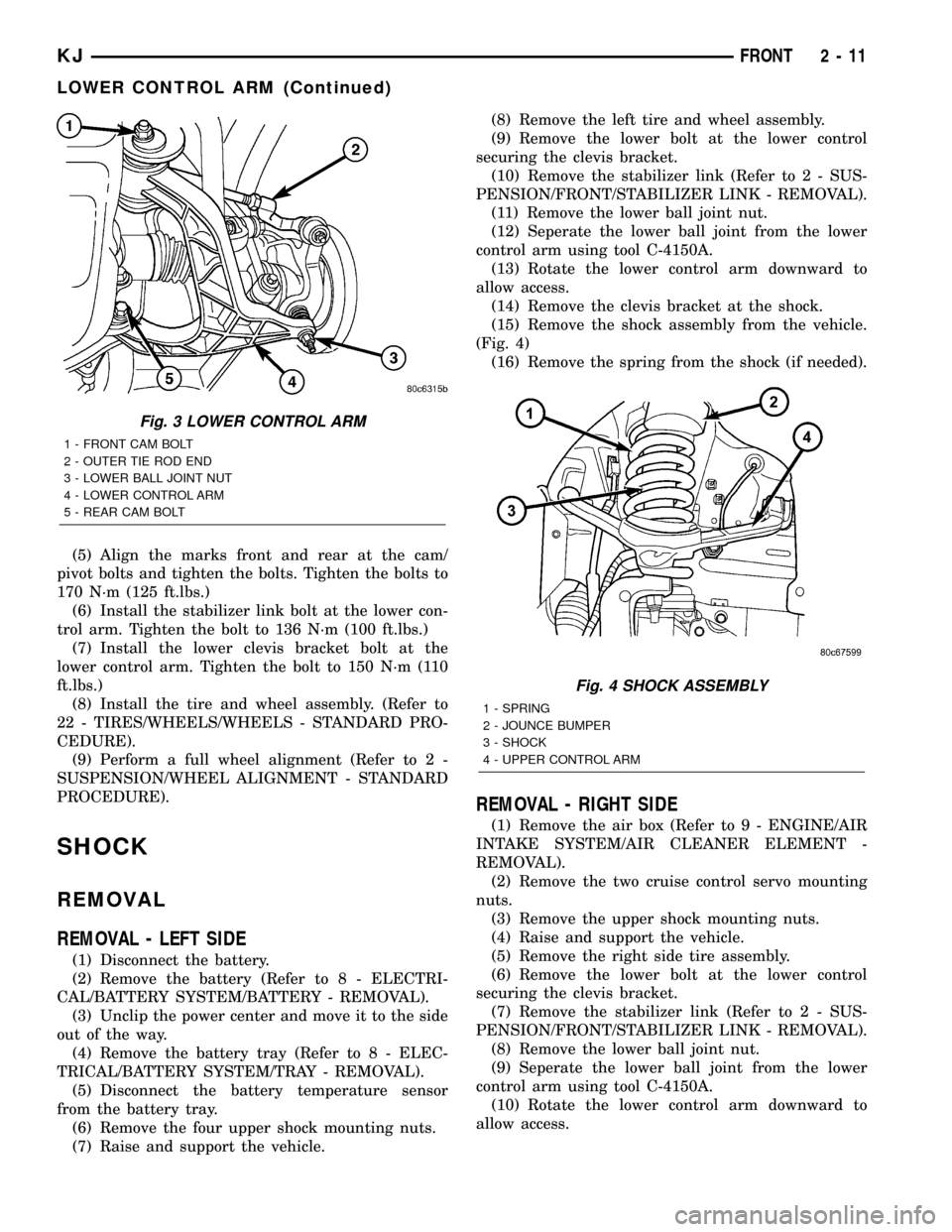
(14) Remove the clevis bracket at the shock.
(15) Remove the shock assembly from the vehicle.
(Fig. 4)
(16) Remove the spring from the shock (if needed).
REMOVAL - RIGHT SIDE
(1) Remove the air box (Refer to 9 - ENGINE/AIR
INTAKE SYSTEM/AIR CLEANER ELEMENT -
REMOVAL).
(2) Remove the two cruise control servo mounting
nuts.
(3) Remove the upper shock mounting nuts.
(4) Raise and support the vehicle.
(5) Remove the right side tire assembly.
(6) Remove the lower bolt at the lower control
securing the clevis bracket.
(7) Remove the stabilizer link (Refer to 2 - SUS-
PENSION/FRONT/STABILIZER LINK - REMOVAL).
(8) Remove the lower ball joint nut.
(9) Seperate the lower ball joint from the lower
control arm using tool C-4150A.
(10) Rotate the lower control arm downward to
allow access.
Fig. 3 LOWER CONTROL ARM
1 - FRONT CAM BOLT
2 - OUTER TIE ROD END
3 - LOWER BALL JOINT NUT
4 - LOWER CONTROL ARM
5 - REAR CAM BOLT
Fig. 4 SHOCK ASSEMBLY
1 - SPRING
2 - JOUNCE BUMPER
3 - SHOCK
4 - UPPER CONTROL ARM
KJFRONT 2 - 11
LOWER CONTROL ARM (Continued)
Page 36 of 1803
REAR
TABLE OF CONTENTS
page page
REAR
DESCRIPTION.........................16
WARNING.............................16
DIAGNOSIS AND TESTING - REAR
SUSPENSION........................17
SPECIFICATIONS
TORQUE CHART......................17
SHOCK
REMOVAL.............................18
INSTALLATION.........................18
SPRING
REMOVAL.............................18
INSTALLATION.........................18
JOUNCE BUMPER
REMOVAL.............................19
INSTALLATION.........................19
STABILIZER BAR
REMOVAL.............................19INSTALLATION.........................19
UPPER BALL JOINT
REMOVAL.............................20
INSTALLATION.........................20
UPPER CONTROL ARM
DESCRIPTION - UPPER SUSPENSION ARM,
BUSHINGS, AND BALL JOINT............20
OPERATION - UPPER SUSPENSION ARM,
BUSHINGS, AND BALL JOINT............20
REMOVAL.............................20
INSTALLATION.........................21
LOWER CONTROL ARM
DESCRIPTION.........................21
OPERATION...........................21
REMOVAL.............................21
INSTALLATION.........................21
REAR
DESCRIPTION
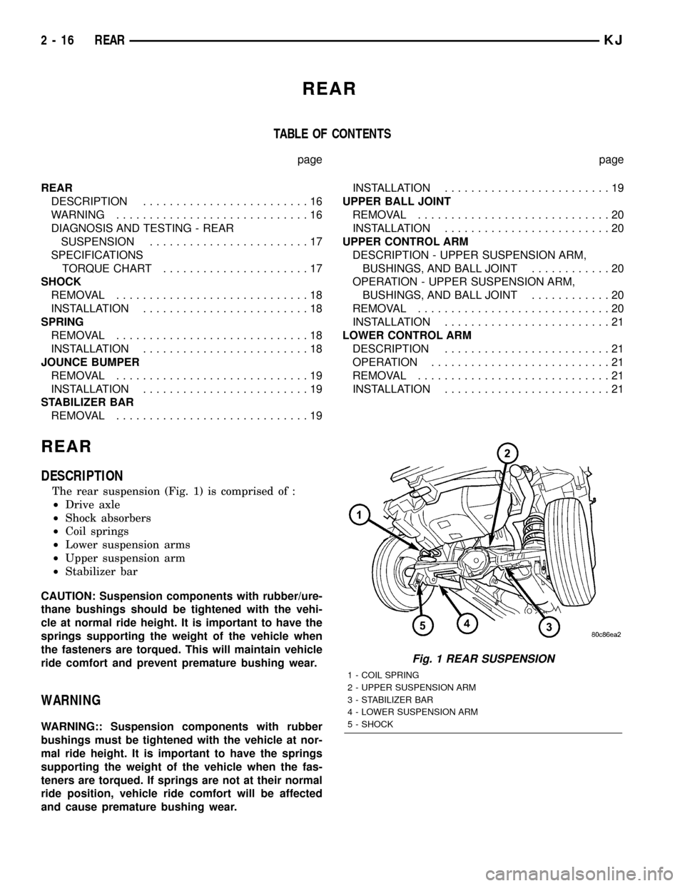
The rear suspension (Fig. 1) is comprised of :
²Drive axle
²Shock absorbers
²Coil springs
²Lower suspension arms
²Upper suspension arm
²Stabilizer bar
CAUTION: Suspension components with rubber/ure-
thane bushings should be tightened with the vehi-
cle at normal ride height. It is important to have the
springs supporting the weight of the vehicle when
the fasteners are torqued. This will maintain vehicle
ride comfort and prevent premature bushing wear.
WARNING
WARNING:: Suspension components with rubber
bushings must be tightened with the vehicle at nor-
mal ride height. It is important to have the springs
supporting the weight of the vehicle when the fas-
teners are torqued. If springs are not at their normal
ride position, vehicle ride comfort will be affected
and cause premature bushing wear.
Fig. 1 REAR SUSPENSION
1 - COIL SPRING
2 - UPPER SUSPENSION ARM
3 - STABILIZER BAR
4 - LOWER SUSPENSION ARM
5 - SHOCK
2 - 16 REARKJ
Page 38 of 1803
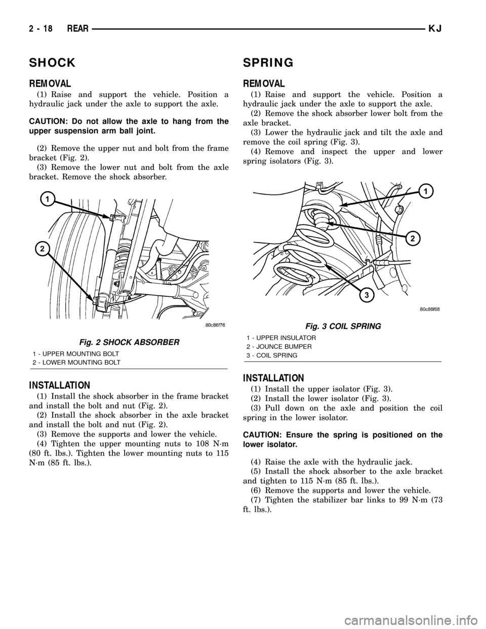
SHOCK
REMOVAL
(1) Raise and support the vehicle. Position a
hydraulic jack under the axle to support the axle.
CAUTION: Do not allow the axle to hang from the
upper suspension arm ball joint.
(2) Remove the upper nut and bolt from the frame
bracket (Fig. 2).
(3) Remove the lower nut and bolt from the axle
bracket. Remove the shock absorber.
INSTALLATION
(1) Install the shock absorber in the frame bracket
and install the bolt and nut (Fig. 2).
(2) Install the shock absorber in the axle bracket
and install the bolt and nut (Fig. 2).
(3) Remove the supports and lower the vehicle.
(4) Tighten the upper mounting nuts to 108 N´m
(80 ft. lbs.). Tighten the lower mounting nuts to 115
N´m (85 ft. lbs.).
SPRING
REMOVAL
(1) Raise and support the vehicle. Position a
hydraulic jack under the axle to support the axle.
(2) Remove the shock absorber lower bolt from the
axle bracket.
(3) Lower the hydraulic jack and tilt the axle and
remove the coil spring (Fig. 3).
(4) Remove and inspect the upper and lower
spring isolators (Fig. 3).
INSTALLATION
(1) Install the upper isolator (Fig. 3).
(2) Install the lower isolator (Fig. 3).
(3) Pull down on the axle and position the coil
spring in the lower isolator.
CAUTION: Ensure the spring is positioned on the
lower isolator.
(4) Raise the axle with the hydraulic jack.
(5) Install the shock absorber to the axle bracket
and tighten to 115 N´m (85 ft. lbs.).
(6) Remove the supports and lower the vehicle.
(7) Tighten the stabilizer bar links to 99 N´m (73
ft. lbs.).
Fig. 2 SHOCK ABSORBER
1 - UPPER MOUNTING BOLT
2 - LOWER MOUNTING BOLT
Fig. 3 COIL SPRING
1 - UPPER INSULATOR
2 - JOUNCE BUMPER
3 - COIL SPRING
2 - 18 REARKJ
Page 39 of 1803
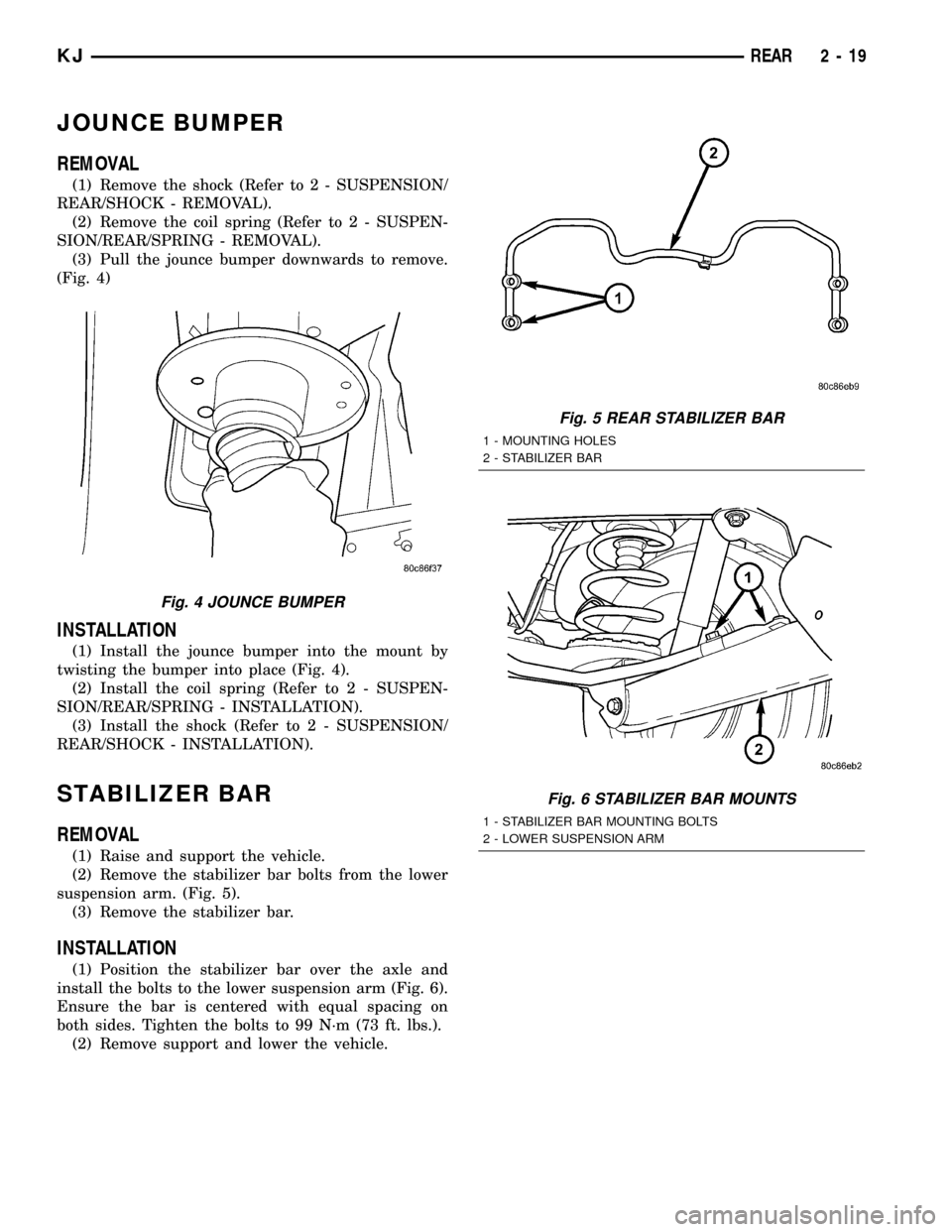
JOUNCE BUMPER
REMOVAL
(1) Remove the shock (Refer to 2 - SUSPENSION/
REAR/SHOCK - REMOVAL).
(2) Remove the coil spring (Refer to 2 - SUSPEN-
SION/REAR/SPRING - REMOVAL).
(3) Pull the jounce bumper downwards to remove.
(Fig. 4)
INSTALLATION
(1) Install the jounce bumper into the mount by
twisting the bumper into place (Fig. 4).
(2) Install the coil spring (Refer to 2 - SUSPEN-
SION/REAR/SPRING - INSTALLATION).
(3) Install the shock (Refer to 2 - SUSPENSION/
REAR/SHOCK - INSTALLATION).
STABILIZER BAR
REMOVAL
(1) Raise and support the vehicle.
(2) Remove the stabilizer bar bolts from the lower
suspension arm. (Fig. 5).
(3) Remove the stabilizer bar.
INSTALLATION
(1) Position the stabilizer bar over the axle and
install the bolts to the lower suspension arm (Fig. 6).
Ensure the bar is centered with equal spacing on
both sides. Tighten the bolts to 99 N´m (73 ft. lbs.).
(2) Remove support and lower the vehicle.
Fig. 4 JOUNCE BUMPER
Fig. 5 REAR STABILIZER BAR
1 - MOUNTING HOLES
2 - STABILIZER BAR
Fig. 6 STABILIZER BAR MOUNTS
1 - STABILIZER BAR MOUNTING BOLTS
2 - LOWER SUSPENSION ARM
KJREAR 2 - 19
Page 40 of 1803
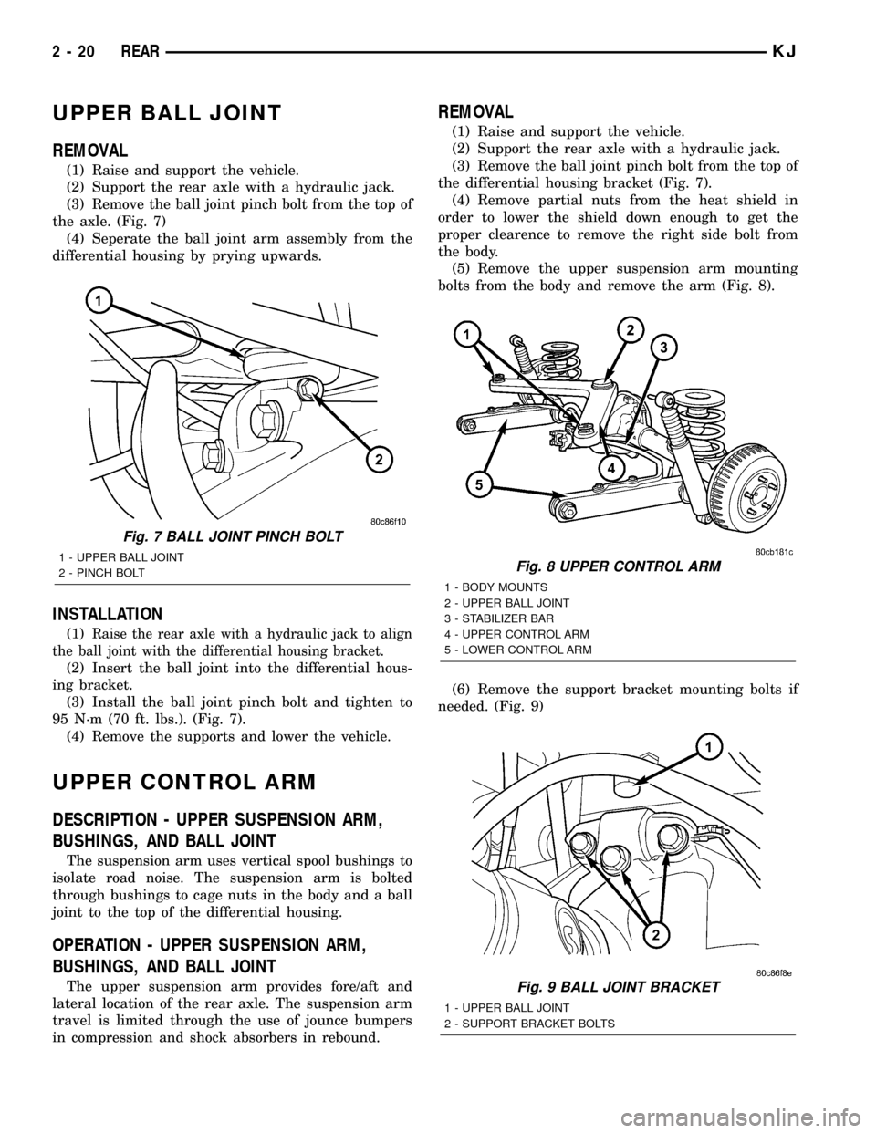
UPPER BALL JOINT
REMOVAL
(1) Raise and support the vehicle.
(2) Support the rear axle with a hydraulic jack.
(3) Remove the ball joint pinch bolt from the top of
the axle. (Fig. 7)
(4) Seperate the ball joint arm assembly from the
differential housing by prying upwards.
INSTALLATION
(1)Raise the rear axle with a hydraulic jack to align
the ball joint with the differential housing bracket.
(2) Insert the ball joint into the differential hous-
ing bracket.
(3) Install the ball joint pinch bolt and tighten to
95 N´m (70 ft. lbs.). (Fig. 7).
(4) Remove the supports and lower the vehicle.
UPPER CONTROL ARM
DESCRIPTION - UPPER SUSPENSION ARM,
BUSHINGS, AND BALL JOINT
The suspension arm uses vertical spool bushings to
isolate road noise. The suspension arm is bolted
through bushings to cage nuts in the body and a ball
joint to the top of the differential housing.
OPERATION - UPPER SUSPENSION ARM,
BUSHINGS, AND BALL JOINT
The upper suspension arm provides fore/aft and
lateral location of the rear axle. The suspension arm
travel is limited through the use of jounce bumpers
in compression and shock absorbers in rebound.
REMOVAL
(1) Raise and support the vehicle.
(2) Support the rear axle with a hydraulic jack.
(3) Remove the ball joint pinch bolt from the top of
the differential housing bracket (Fig. 7).
(4) Remove partial nuts from the heat shield in
order to lower the shield down enough to get the
proper clearence to remove the right side bolt from
the body.
(5) Remove the upper suspension arm mounting
bolts from the body and remove the arm (Fig. 8).
(6) Remove the support bracket mounting bolts if
needed. (Fig. 9)
Fig. 7 BALL JOINT PINCH BOLT
1 - UPPER BALL JOINT
2 - PINCH BOLTFig. 8 UPPER CONTROL ARM
1 - BODY MOUNTS
2 - UPPER BALL JOINT
3 - STABILIZER BAR
4 - UPPER CONTROL ARM
5 - LOWER CONTROL ARM
Fig. 9 BALL JOINT BRACKET
1 - UPPER BALL JOINT
2 - SUPPORT BRACKET BOLTS
2 - 20 REARKJ
Page 443 of 1803
HEADLAMP LEVELING MOTOR
DESCRIPTION.........................35
OPERATION...........................36
REMOVAL.............................36
INSTALLATION.........................36
HEADLAMP LEVELING SWITCH
DESCRIPTION.........................37
OPERATION...........................37
DIAGNOSIS AND TESTING - HEADLAMP
LEVELING SWITCH....................37
REMOVAL.............................38
INSTALLATION.........................38
HEADLAMP LOW BEAM RELAY
DESCRIPTION.........................39
OPERATION...........................39
DIAGNOSIS AND TESTING - HEADLAMP LOW
BEAM RELAY........................40
REMOVAL.............................40
INSTALLATION.........................41
HEADLAMP UNIT
REMOVAL.............................41
INSTALLATION.........................42
ADJUSTMENTS
ADJUSTMENT - HEADLAMP UNIT........42
LICENSE PLATE LAMP BULB
REMOVAL.............................44
INSTALLATION.........................45
LICENSE PLATE LAMP UNIT
REMOVAL.............................45
INSTALLATION.........................46
MULTI-FUNCTION SWITCH
DESCRIPTION.........................46
OPERATION...........................48
DIAGNOSIS AND TESTING - MULTI-
FUNCTION SWITCH...................50
REMOVAL.............................53
INSTALLATION.........................53
PARK LAMP RELAY
DESCRIPTION.........................54OPERATION...........................54
DIAGNOSIS AND TESTING - PARK LAMP
RELAY..............................55
REMOVAL.............................55
INSTALLATION.........................56
REAR FOG LAMP RELAY
DESCRIPTION.........................56
OPERATION...........................57
DIAGNOSIS AND TESTING - REAR FOG
LAMP RELAY.........................57
REMOVAL.............................58
INSTALLATION.........................58
REAR LAMP BULB
REMOVAL.............................58
INSTALLATION.........................59
REAR LAMP UNIT
REMOVAL.............................59
INSTALLATION.........................60
REPEATER LAMP BULB
REMOVAL.............................60
INSTALLATION.........................60
REPEATER LAMP UNIT
REMOVAL.............................60
INSTALLATION.........................61
TRAILER TOW CONNECTOR
REMOVAL.............................61
INSTALLATION.........................61
TRAILER TOW RELAY
DESCRIPTION.........................61
OPERATION...........................62
DIAGNOSIS AND TESTING - TRAILER TOW
RELAY..............................62
REMOVAL.............................63
INSTALLATION.........................64
TRAILER TOW WIRING
DESCRIPTION.........................64
LAMPS/LIGHTING - EXTERIOR
DESCRIPTION
The exterior lighting system for this model
includes the following exterior lamps (Fig. 1):
²Backup Lamps- The backup (or reverse) lamps
are integral to the rear lamp units mounted to the
back of the quarter panel on each side of the tailgate
at the rear of the vehicle.
²Brake Lamps- The brake (or stop) lamps
include a lamp that is integral to the rear lamp units
mounted to the back of the quarter panel on each
side of the tailgate, and the Center High Mounted
Stop Lamp (CHMSL) that is centered on the rear
edge of the roof panel above the flip-up glass opening
at the rear of the vehicle.²Daytime Running Lamps- Vehicles manufac-
tured for sale in Canada illuminate the high beam
filament in each headlamp bulb serves as the Day-
time Running Lamps (DRL).
²Front Fog Lamps- Optional front fog lamps
include a single round front fog lamp unit with an
adjustable reflector and a removable bulb that is
secured behind a dedicated opening on each forward-
facing end of the front bumper fascia.
²Hazard Warning Lamps- The hazard warning
lamps include all of the right and left turn signal
lamps.
²Headlamps- A single round headlamp housing
with a fixed lens, an adjustable reflector, and a single
removable halogen bulb is secured to the grille open-
ing panel on each side of the grille opening at the
8L - 2 LAMPS/LIGHTING - EXTERIORKJ
Page 445 of 1803
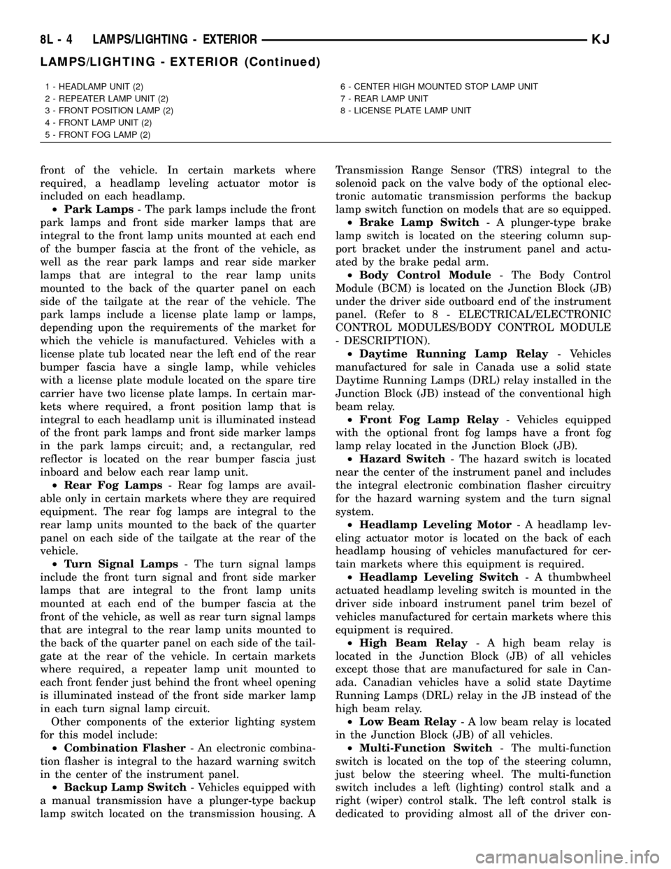
front of the vehicle. In certain markets where
required, a headlamp leveling actuator motor is
included on each headlamp.
²Park Lamps- The park lamps include the front
park lamps and front side marker lamps that are
integral to the front lamp units mounted at each end
of the bumper fascia at the front of the vehicle, as
well as the rear park lamps and rear side marker
lamps that are integral to the rear lamp units
mounted to the back of the quarter panel on each
side of the tailgate at the rear of the vehicle. The
park lamps include a license plate lamp or lamps,
depending upon the requirements of the market for
which the vehicle is manufactured. Vehicles with a
license plate tub located near the left end of the rear
bumper fascia have a single lamp, while vehicles
with a license plate module located on the spare tire
carrier have two license plate lamps. In certain mar-
kets where required, a front position lamp that is
integral to each headlamp unit is illuminated instead
of the front park lamps and front side marker lamps
in the park lamps circuit; and, a rectangular, red
reflector is located on the rear bumper fascia just
inboard and below each rear lamp unit.
²Rear Fog Lamps- Rear fog lamps are avail-
able only in certain markets where they are required
equipment. The rear fog lamps are integral to the
rear lamp units mounted to the back of the quarter
panel on each side of the tailgate at the rear of the
vehicle.
²Turn Signal Lamps- The turn signal lamps
include the front turn signal and front side marker
lamps that are integral to the front lamp units
mounted at each end of the bumper fascia at the
front of the vehicle, as well as rear turn signal lamps
that are integral to the rear lamp units mounted to
the back of the quarter panel on each side of the tail-
gate at the rear of the vehicle. In certain markets
where required, a repeater lamp unit mounted to
each front fender just behind the front wheel opening
is illuminated instead of the front side marker lamp
in each turn signal lamp circuit.
Other components of the exterior lighting system
for this model include:
²Combination Flasher- An electronic combina-
tion flasher is integral to the hazard warning switch
in the center of the instrument panel.
²Backup Lamp Switch- Vehicles equipped with
a manual transmission have a plunger-type backup
lamp switch located on the transmission housing. ATransmission Range Sensor (TRS) integral to the
solenoid pack on the valve body of the optional elec-
tronic automatic transmission performs the backup
lamp switch function on models that are so equipped.
²Brake Lamp Switch- A plunger-type brake
lamp switch is located on the steering column sup-
port bracket under the instrument panel and actu-
ated by the brake pedal arm.
²Body Control Module- The Body Control
Module (BCM) is located on the Junction Block (JB)
under the driver side outboard end of the instrument
panel. (Refer to 8 - ELECTRICAL/ELECTRONIC
CONTROL MODULES/BODY CONTROL MODULE
- DESCRIPTION).
²Daytime Running Lamp Relay- Vehicles
manufactured for sale in Canada use a solid state
Daytime Running Lamps (DRL) relay installed in the
Junction Block (JB) instead of the conventional high
beam relay.
²Front Fog Lamp Relay- Vehicles equipped
with the optional front fog lamps have a front fog
lamp relay located in the Junction Block (JB).
²Hazard Switch- The hazard switch is located
near the center of the instrument panel and includes
the integral electronic combination flasher circuitry
for the hazard warning system and the turn signal
system.
²Headlamp Leveling Motor- A headlamp lev-
eling actuator motor is located on the back of each
headlamp housing of vehicles manufactured for cer-
tain markets where this equipment is required.
²Headlamp Leveling Switch- A thumbwheel
actuated headlamp leveling switch is mounted in the
driver side inboard instrument panel trim bezel of
vehicles manufactured for certain markets where this
equipment is required.
²High Beam Relay- A high beam relay is
located in the Junction Block (JB) of all vehicles
except those that are manufactured for sale in Can-
ada. Canadian vehicles have a solid state Daytime
Running Lamps (DRL) relay in the JB instead of the
high beam relay.
²Low Beam Relay- A low beam relay is located
in the Junction Block (JB) of all vehicles.
²Multi-Function Switch- The multi-function
switch is located on the top of the steering column,
just below the steering wheel. The multi-function
switch includes a left (lighting) control stalk and a
right (wiper) control stalk. The left control stalk is
dedicated to providing almost all of the driver con-
1 - HEADLAMP UNIT (2)
2 - REPEATER LAMP UNIT (2)
3 - FRONT POSITION LAMP (2)
4 - FRONT LAMP UNIT (2)
5 - FRONT FOG LAMP (2)6 - CENTER HIGH MOUNTED STOP LAMP UNIT
7 - REAR LAMP UNIT
8 - LICENSE PLATE LAMP UNIT
8L - 4 LAMPS/LIGHTING - EXTERIORKJ
LAMPS/LIGHTING - EXTERIOR (Continued)
Page 466 of 1803
FRONT FOG LAMP UNIT
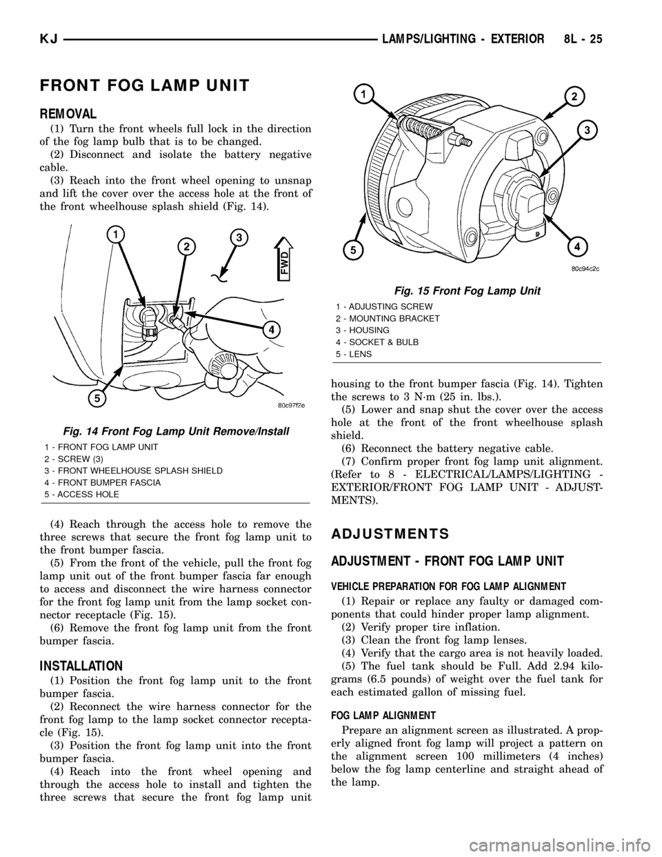
REMOVAL
(1) Turn the front wheels full lock in the direction
of the fog lamp bulb that is to be changed.
(2) Disconnect and isolate the battery negative
cable.
(3) Reach into the front wheel opening to unsnap
and lift the cover over the access hole at the front of
the front wheelhouse splash shield (Fig. 14).
(4) Reach through the access hole to remove the
three screws that secure the front fog lamp unit to
the front bumper fascia.
(5) From the front of the vehicle, pull the front fog
lamp unit out of the front bumper fascia far enough
to access and disconnect the wire harness connector
for the front fog lamp unit from the lamp socket con-
nector receptacle (Fig. 15).
(6) Remove the front fog lamp unit from the front
bumper fascia.
INSTALLATION
(1) Position the front fog lamp unit to the front
bumper fascia.
(2) Reconnect the wire harness connector for the
front fog lamp to the lamp socket connector recepta-
cle (Fig. 15).
(3) Position the front fog lamp unit into the front
bumper fascia.
(4) Reach into the front wheel opening and
through the access hole to install and tighten the
three screws that secure the front fog lamp unithousing to the front bumper fascia (Fig. 14). Tighten
the screws to 3 N´m (25 in. lbs.).
(5) Lower and snap shut the cover over the access
hole at the front of the front wheelhouse splash
shield.
(6) Reconnect the battery negative cable.
(7) Confirm proper front fog lamp unit alignment.
(Refer to 8 - ELECTRICAL/LAMPS/LIGHTING -
EXTERIOR/FRONT FOG LAMP UNIT - ADJUST-
MENTS).
ADJUSTMENTS
ADJUSTMENT - FRONT FOG LAMP UNIT
VEHICLE PREPARATION FOR FOG LAMP ALIGNMENT
(1) Repair or replace any faulty or damaged com-
ponents that could hinder proper lamp alignment.
(2) Verify proper tire inflation.
(3) Clean the front fog lamp lenses.
(4) Verify that the cargo area is not heavily loaded.
(5) The fuel tank should be Full. Add 2.94 kilo-
grams (6.5 pounds) of weight over the fuel tank for
each estimated gallon of missing fuel.
FOG LAMP ALIGNMENT
Prepare an alignment screen as illustrated. A prop-
erly aligned front fog lamp will project a pattern on
the alignment screen 100 millimeters (4 inches)
below the fog lamp centerline and straight ahead of
the lamp.
Fig. 14 Front Fog Lamp Unit Remove/Install
1 - FRONT FOG LAMP UNIT
2 - SCREW (3)
3 - FRONT WHEELHOUSE SPLASH SHIELD
4 - FRONT BUMPER FASCIA
5 - ACCESS HOLE
Fig. 15 Front Fog Lamp Unit
1 - ADJUSTING SCREW
2 - MOUNTING BRACKET
3 - HOUSING
4 - SOCKET & BULB
5 - LENS
KJLAMPS/LIGHTING - EXTERIOR 8L - 25