Termine JEEP LIBERTY 2002 KJ / 1.G Workshop Manual
[x] Cancel search | Manufacturer: JEEP, Model Year: 2002, Model line: LIBERTY, Model: JEEP LIBERTY 2002 KJ / 1.GPages: 1803, PDF Size: 62.3 MB
Page 4 of 1803
INTRODUCTION
TABLE OF CONTENTS
page page
FASTENER IDENTIFICATION
DESCRIPTION..........................1
FASTENER USAGE
DESCRIPTION
DESCRIPTION........................4
DESCRIPTION........................4
THREADED HOLE REPAIR
DESCRIPTION..........................4
INTERNATIONAL SYMBOLS
DESCRIPTION..........................4
METRIC SYSTEM
DESCRIPTION..........................5TORQUE REFERENCES
DESCRIPTION..........................7
VEHICLE EMISSION CONTROL INFORMATION
(VECI) LABEL
DESCRIPTION..........................8
VEHICLE IDENTIFICATION NUMBER
DESCRIPTION..........................8
VEHICLE SAFETY CERTIFICATION LABEL
DESCRIPTION..........................9
FASTENER IDENTIFICATION
DESCRIPTION
The SAE bolt strength grades range from grade 2
to grade 8. The higher the grade number, the greater
the bolt strength. Identification is determined by the
line marks on the top of each bolt head. The actual
bolt strength grade corresponds to the number of linemarks plus 2. The most commonly used metric bolt
strength classes are 9.8 and 10.9. The metric
strength class identification number is imprinted on
the head of the bolt. The higher the class number,
the greater the bolt strength. Some metric nuts are
imprinted with a single-digit strength class on the
nut face. Refer to the Fastener Identification and
Fastener Strength Charts (Fig. 1) and (Fig. 2).
KJINTRODUCTION 1
Page 11 of 1803
VEHICLE EMISSION CONTROL
INFORMATION (VECI) LABEL
DESCRIPTION
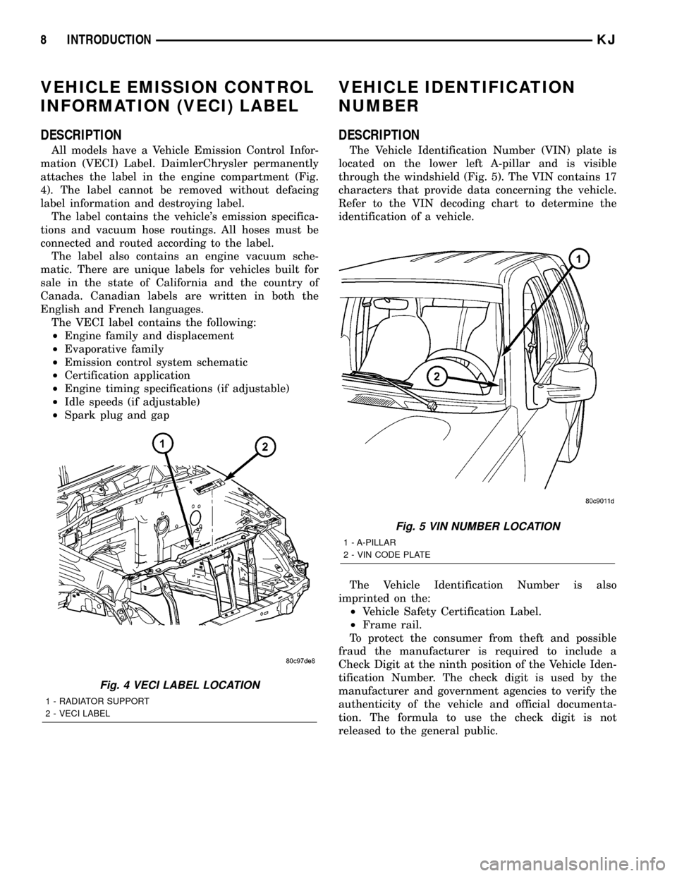
All models have a Vehicle Emission Control Infor-
mation (VECI) Label. DaimlerChrysler permanently
attaches the label in the engine compartment (Fig.
4). The label cannot be removed without defacing
label information and destroying label.
The label contains the vehicle's emission specifica-
tions and vacuum hose routings. All hoses must be
connected and routed according to the label.
The label also contains an engine vacuum sche-
matic. There are unique labels for vehicles built for
sale in the state of California and the country of
Canada. Canadian labels are written in both the
English and French languages.
The VECI label contains the following:
²Engine family and displacement
²Evaporative family
²Emission control system schematic
²Certification application
²Engine timing specifications (if adjustable)
²Idle speeds (if adjustable)
²Spark plug and gap
VEHICLE IDENTIFICATION
NUMBER
DESCRIPTION
The Vehicle Identification Number (VIN) plate is
located on the lower left A-pillar and is visible
through the windshield (Fig. 5). The VIN contains 17
characters that provide data concerning the vehicle.
Refer to the VIN decoding chart to determine the
identification of a vehicle.
The Vehicle Identification Number is also
imprinted on the:
²Vehicle Safety Certification Label.
²Frame rail.
To protect the consumer from theft and possible
fraud the manufacturer is required to include a
Check Digit at the ninth position of the Vehicle Iden-
tification Number. The check digit is used by the
manufacturer and government agencies to verify the
authenticity of the vehicle and official documenta-
tion. The formula to use the check digit is not
released to the general public.
Fig. 4 VECI LABEL LOCATION
1 - RADIATOR SUPPORT
2 - VECI LABEL
Fig. 5 VIN NUMBER LOCATION
1 - A-PILLAR
2 - VIN CODE PLATE
8 INTRODUCTIONKJ
Page 24 of 1803
STANDARD PROCEDURE
STANDARD PROCEDURE - HEIGHT
MEASUREMENT
RIDE HEIGHT
NOTE: The suspension is non-adjustable.
The vehicle suspension height should be measured
before performing wheel alignment procedure. Also
when front suspension components have been
replaced. This measure must be performed with the
vehicle supporting it's own weight and taken on both
sides of the vehicle.
Front and rear ride heights are not adjustable. The
spring selections at assembly determine ride height
for acceptable appearance of the vehicle. Ride height
dimensions assume full fluids (including fuel) and
zero passengers. Refer to the table below for front
ride height dimensions.
Vehicle ride height audits should be performed uti-
lizing the following procedure:
(1) Drive the vehicle straight and forward on a
non-tacky surface for a minimum of 20 feet to neu-
tralize track width.
(2) Bounce the front of the vehicle five times.
(3) Measure and record the dimensions
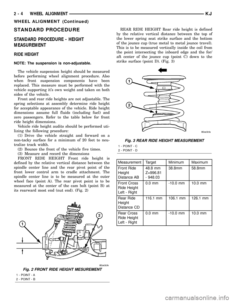
FRONT RIDE HEIGHT Front ride height is
defined by the relative vertical distance between the
spindle center line and the rear pivot point of the
front lower control arm to cradle attachment. The
spindle center line is to be measured at the outer
wheel face (point A). The rear pivot point is to be
measured at the center of the cam bolt (point B) at
its rearward most end (nut end). (Fig. 2)REAR RIDE HEIGHT Rear ride height is defined
by the relative vertical distance between the top of
the lower spring seat strike surface and the bottom
of the jounce cup (true metal to metal jounce travel).
This is to be measured vertically inside the coil from
the point intersecting the inboard edge and the for/
aft center of the jounce cup (point C) down to the
strike surface (point D). (Fig. 3)
Measurement Target Minimum Maximum
Front Ride
Height
Distance AB48.8 mm
Z=996.81
- 948.0338.8mm 58.8mm
Front Cross
Ride Height
Left - Right0.0 mm -10.0 mm 10.0 mm
Rear Ride
Height
Distance CD116.1 mm 106.1 mm 126.1 mm
Rear Cross
Ride Height
Left - Right0.0 mm -10.0 mm 10.0 mm
Fig. 2 FRONT RIDE HEIGHT MESUREMENT
1 - POINT - A
2 - POINT - B
Fig. 3 REAR RIDE HEIGHT MEASUREMENT
1 - POINT - C
2 - POINT - D
2 - 4 WHEEL ALIGNMENTKJ
WHEEL ALIGNMENT (Continued)
Page 76 of 1803
PINION DEPTH MEASUREMENT
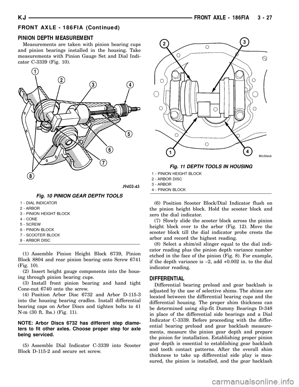
Measurements are taken with pinion bearing cups
and pinion bearings installed in the housing. Take
measurements with Pinion Gauge Set and Dial Indi-
cator C-3339 (Fig. 10).
(1) Assemble Pinion Height Block 6739, Pinion
Block 8804 and rear pinion bearing onto Screw 6741
(Fig. 10).
(2) Insert height gauge components into the hous-
ing through pinion bearing cups.
(3) Install front pinion bearing and hand tight
Cone-nut 6740 onto the screw.
(4) Position Arbor Disc 6732 and Arbor D-115-3
into the housing bearing cradles. Install differential
bearing caps on Arbor Discs and tighten bolts to 41
N´m (30 ft. lbs.) (Fig. 11).
NOTE: Arbor Discs 6732 has different step diame-
ters to fit other axles. Choose proper step for axle
being serviced.
(5) Assemble Dial Indicator C-3339 into Scooter
Block D-115-2 and secure set screw.(6) Position Scooter Block/Dial Indicator flush on
the pinion height block. Hold the scooter block and
zero the dial indicator.
(7) Slowly slide the scooter block across the pinion
height block over to the arbor (Fig. 12). Move the
scooter block till the dial indicator probe crests the
arbor and record the highest reading.
(8) Select a shim/oil slinger equal to the dial indi-
cator reading plus the pinion depth variance number
etched in the face of the pinion (Fig. 8). For example,
if the depth variance is ±2, add +0.002 in. to the dial
indicator reading.
DIFFERENTIAL
Differential bearing preload and gear backlash is
adjusted by the use of selective shims. The shims are
located between the differential bearing cups and the
differential housing. The proper shim thickness can
be determined using slip-fit Dummy Bearings D-348
in place of the differential side bearings and a Dial
Indicator C-3339. Before proceeding with the differ-
ential bearing preload and gear backlash measure-
ments, measure the pinion gear depth and prepare
the pinion for installation. Establishing proper pinion
gear depth is essential to establishing gear backlash
and tooth contact patterns. After the overall shim
thickness to take up differential side play is mea-
sured, the pinion is installed, and the gear backlash
Fig. 10 PINION GEAR DEPTH TOOLS
1 - DIAL INDICATOR
2 - ARBOR
3 - PINION HEIGHT BLOCK
4 - CONE
5 - SCREW
6 - PINION BLOCK
7 - SCOOTER BLOCK
8 - ARBOR DISC
Fig. 11 DEPTH TOOLS IN HOUSING
1 - PINION HEIGHT BLOCK
2 - ARBOR DISC
3 - ARBOR
4 - PINION BLOCK
KJFRONT AXLE - 186FIA 3 - 27
FRONT AXLE - 186FIA (Continued)
Page 77 of 1803
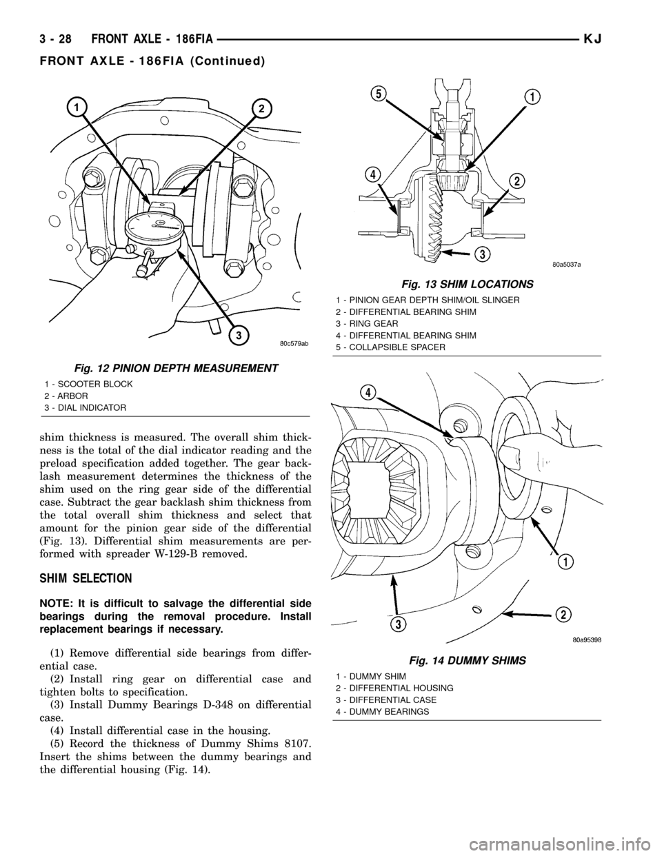
shim thickness is measured. The overall shim thick-
ness is the total of the dial indicator reading and the
preload specification added together. The gear back-
lash measurement determines the thickness of the
shim used on the ring gear side of the differential
case. Subtract the gear backlash shim thickness from
the total overall shim thickness and select that
amount for the pinion gear side of the differential
(Fig. 13). Differential shim measurements are per-
formed with spreader W-129-B removed.
SHIM SELECTION
NOTE: It is difficult to salvage the differential side
bearings during the removal procedure. Install
replacement bearings if necessary.
(1) Remove differential side bearings from differ-
ential case.
(2) Install ring gear on differential case and
tighten bolts to specification.
(3) Install Dummy Bearings D-348 on differential
case.
(4) Install differential case in the housing.
(5) Record the thickness of Dummy Shims 8107.
Insert the shims between the dummy bearings and
the differential housing (Fig. 14).
Fig. 12 PINION DEPTH MEASUREMENT
1 - SCOOTER BLOCK
2 - ARBOR
3 - DIAL INDICATOR
Fig. 13 SHIM LOCATIONS
1 - PINION GEAR DEPTH SHIM/OIL SLINGER
2 - DIFFERENTIAL BEARING SHIM
3 - RING GEAR
4 - DIFFERENTIAL BEARING SHIM
5 - COLLAPSIBLE SPACER
Fig. 14 DUMMY SHIMS
1 - DUMMY SHIM
2 - DIFFERENTIAL HOUSING
3 - DIFFERENTIAL CASE
4 - DUMMY BEARINGS
3 - 28 FRONT AXLE - 186FIAKJ
FRONT AXLE - 186FIA (Continued)
Page 106 of 1803
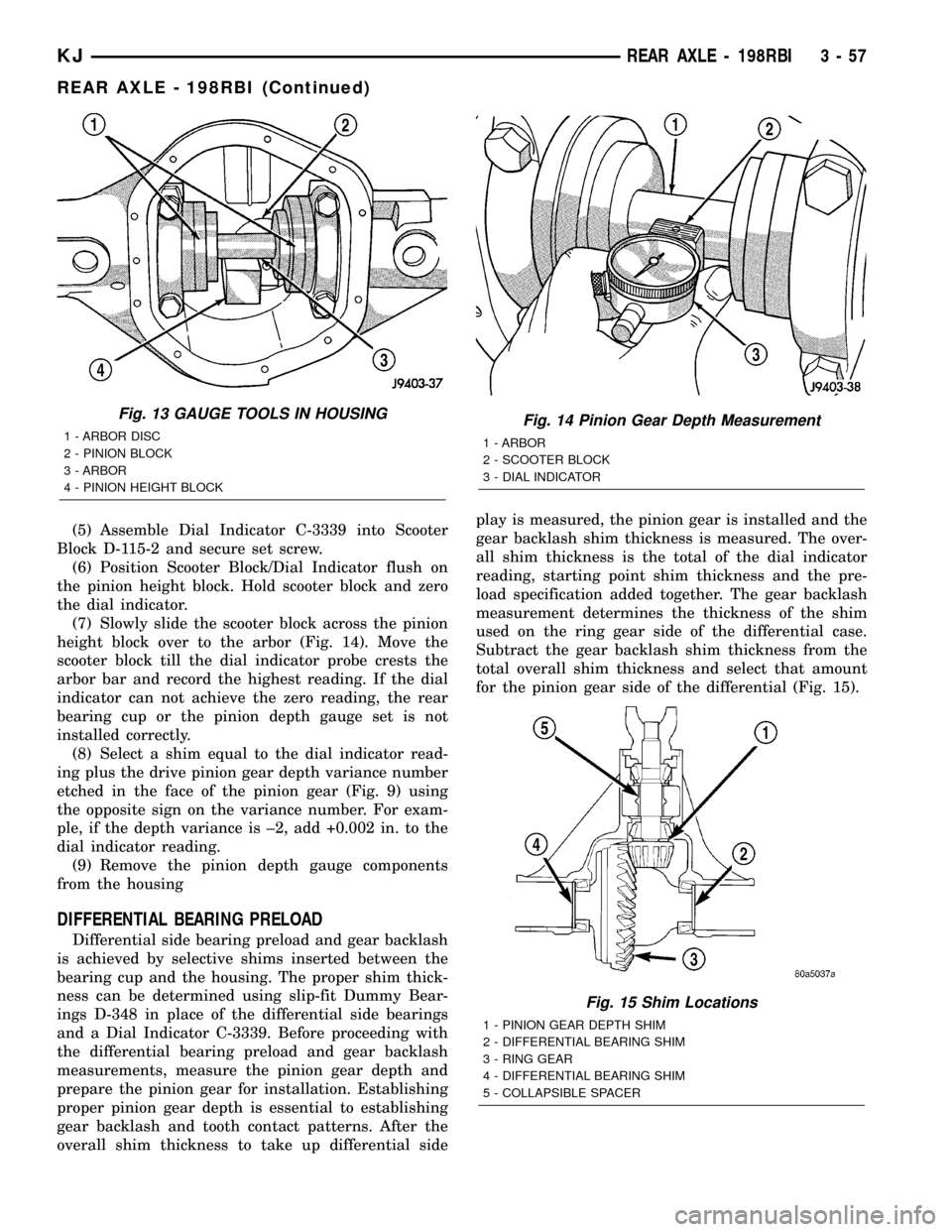
(5) Assemble Dial Indicator C-3339 into Scooter
Block D-115-2 and secure set screw.
(6) Position Scooter Block/Dial Indicator flush on
the pinion height block. Hold scooter block and zero
the dial indicator.
(7) Slowly slide the scooter block across the pinion
height block over to the arbor (Fig. 14). Move the
scooter block till the dial indicator probe crests the
arbor bar and record the highest reading. If the dial
indicator can not achieve the zero reading, the rear
bearing cup or the pinion depth gauge set is not
installed correctly.
(8) Select a shim equal to the dial indicator read-
ing plus the drive pinion gear depth variance number
etched in the face of the pinion gear (Fig. 9) using
the opposite sign on the variance number. For exam-
ple, if the depth variance is ±2, add +0.002 in. to the
dial indicator reading.
(9) Remove the pinion depth gauge components
from the housing
DIFFERENTIAL BEARING PRELOAD
Differential side bearing preload and gear backlash
is achieved by selective shims inserted between the
bearing cup and the housing. The proper shim thick-
ness can be determined using slip-fit Dummy Bear-
ings D-348 in place of the differential side bearings
and a Dial Indicator C-3339. Before proceeding with
the differential bearing preload and gear backlash
measurements, measure the pinion gear depth and
prepare the pinion gear for installation. Establishing
proper pinion gear depth is essential to establishing
gear backlash and tooth contact patterns. After the
overall shim thickness to take up differential sideplay is measured, the pinion gear is installed and the
gear backlash shim thickness is measured. The over-
all shim thickness is the total of the dial indicator
reading, starting point shim thickness and the pre-
load specification added together. The gear backlash
measurement determines the thickness of the shim
used on the ring gear side of the differential case.
Subtract the gear backlash shim thickness from the
total overall shim thickness and select that amount
for the pinion gear side of the differential (Fig. 15).
Fig. 13 GAUGE TOOLS IN HOUSING
1 - ARBOR DISC
2 - PINION BLOCK
3 - ARBOR
4 - PINION HEIGHT BLOCKFig. 14 Pinion Gear Depth Measurement
1 - ARBOR
2 - SCOOTER BLOCK
3 - DIAL INDICATOR
Fig. 15 Shim Locations
1 - PINION GEAR DEPTH SHIM
2 - DIFFERENTIAL BEARING SHIM
3 - RING GEAR
4 - DIFFERENTIAL BEARING SHIM
5 - COLLAPSIBLE SPACER
KJREAR AXLE - 198RBI 3 - 57
REAR AXLE - 198RBI (Continued)
Page 108 of 1803
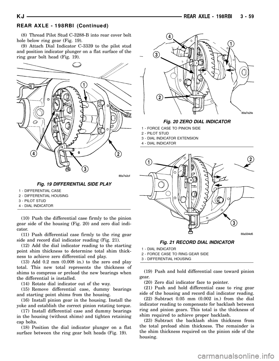
(8) Thread Pilot Stud C-3288-B into rear cover bolt
hole below ring gear (Fig. 19).
(9) Attach Dial Indicator C-3339 to the pilot stud
and position indicator plunger on a flat surface of the
ring gear bolt head (Fig. 19).
(10) Push the differential case firmly to the pinion
gear side of the housing (Fig. 20) and zero dial indi-
cator.
(11) Push differential case firmly to the ring gear
side and record dial indicator reading (Fig. 21).
(12) Add the dial indicator reading to the starting
point shim thickness to determine total shim thick-
ness to achieve zero differential end play.
(13) Add 0.2 mm (0.008 in.) to the zero end play
total. This new total represents the thickness of
shims to compress or preload the new bearings when
the differential is installed.
(14) Rotate dial indicator out of the way.
(15) Remove differential case, dummy bearings
and starting point shims from the housing.
(16) Install pinion gear in the housing. Install the
yoke and establish the correct pinion rotating torque.
(17) Install differential case and dummy bearings
in the housing (without shims) and tighten retaining
cap bolts.
(18) Position the dial indicator plunger on a flat
surface between the ring gear bolt heads (Fig. 19).(19) Push and hold differential case toward pinion
gear.
(20) Zero dial indicator face to pointer.
(21) Push and hold differential case to ring gear
side of the housing and record dial indicator reading.
(22) Subtract 0.05 mm (0.002 in.) from the dial
indicator reading to compensate for backlash between
ring and pinion gears. This total is the thickness of
shim required to achieve proper backlash.
(23) Subtract the backlash shim thickness from
the total preload shim thickness. The remainder is
the shim thickness required on the pinion side of the
housing.
Fig. 19 DIFFERENTIAL SIDE PLAY
1 - DIFFERENTIAL CASE
2 - DIFFERENTIAL HOUSING
3 - PILOT STUD
4 - DIAL INDICATOR
Fig. 20 ZERO DIAL INDICATOR
1 - FORCE CASE TO PINION SIDE
2 - PILOT STUD
3 - DIAL INDICATOR EXTENSION
4 - DIAL INDICATOR
Fig. 21 RECORD DIAL INDICATOR
1 - DIAL INDICATOR
2 - FORCE CASE TO RING GEAR SIDE
3 - DIFFERENTIAL HOUSING
KJREAR AXLE - 198RBI 3 - 59
REAR AXLE - 198RBI (Continued)
Page 122 of 1803
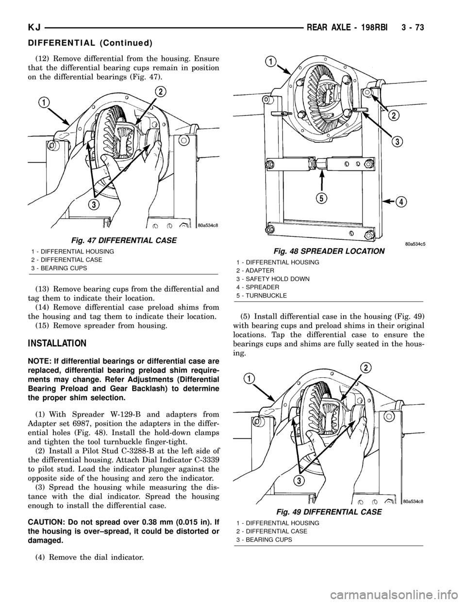
(12) Remove differential from the housing. Ensure
that the differential bearing cups remain in position
on the differential bearings (Fig. 47).
(13) Remove bearing cups from the differential and
tag them to indicate their location.
(14) Remove differential case preload shims from
the housing and tag them to indicate their location.
(15) Remove spreader from housing.
INSTALLATION
NOTE: If differential bearings or differential case are
replaced, differential bearing preload shim require-
ments may change. Refer Adjustments (Differential
Bearing Preload and Gear Backlash) to determine
the proper shim selection.
(1) With Spreader W-129-B and adapters from
Adapter set 6987, position the adapters in the differ-
ential holes (Fig. 48). Install the hold-down clamps
and tighten the tool turnbuckle finger-tight.
(2) Install a Pilot Stud C-3288-B at the left side of
the differential housing. Attach Dial Indicator C-3339
to pilot stud. Load the indicator plunger against the
opposite side of the housing and zero the indicator.
(3) Spread the housing while measuring the dis-
tance with the dial indicator. Spread the housing
enough to install the differential case.
CAUTION: Do not spread over 0.38 mm (0.015 in). If
the housing is over±spread, it could be distorted or
damaged.
(4) Remove the dial indicator.(5) Install differential case in the housing (Fig. 49)
with bearing cups and preload shims in their original
locations. Tap the differential case to ensure the
bearings cups and shims are fully seated in the hous-
ing.
Fig. 47 DIFFERENTIAL CASE
1 - DIFFERENTIAL HOUSING
2 - DIFFERENTIAL CASE
3 - BEARING CUPSFig. 48 SPREADER LOCATION
1 - DIFFERENTIAL HOUSING
2 - ADAPTER
3 - SAFETY HOLD DOWN
4 - SPREADER
5 - TURNBUCKLE
Fig. 49 DIFFERENTIAL CASE
1 - DIFFERENTIAL HOUSING
2 - DIFFERENTIAL CASE
3 - BEARING CUPS
KJREAR AXLE - 198RBI 3 - 73
DIFFERENTIAL (Continued)
Page 146 of 1803
SIDE GEAR CLEARANCE
NOTE: When measuring side gear clearance, check
each gear independently. If it necessary to replace a
side gear, replace both gears as a matched set.
(1) Install the axle shafts, C-locks and pinion mate
shaft.
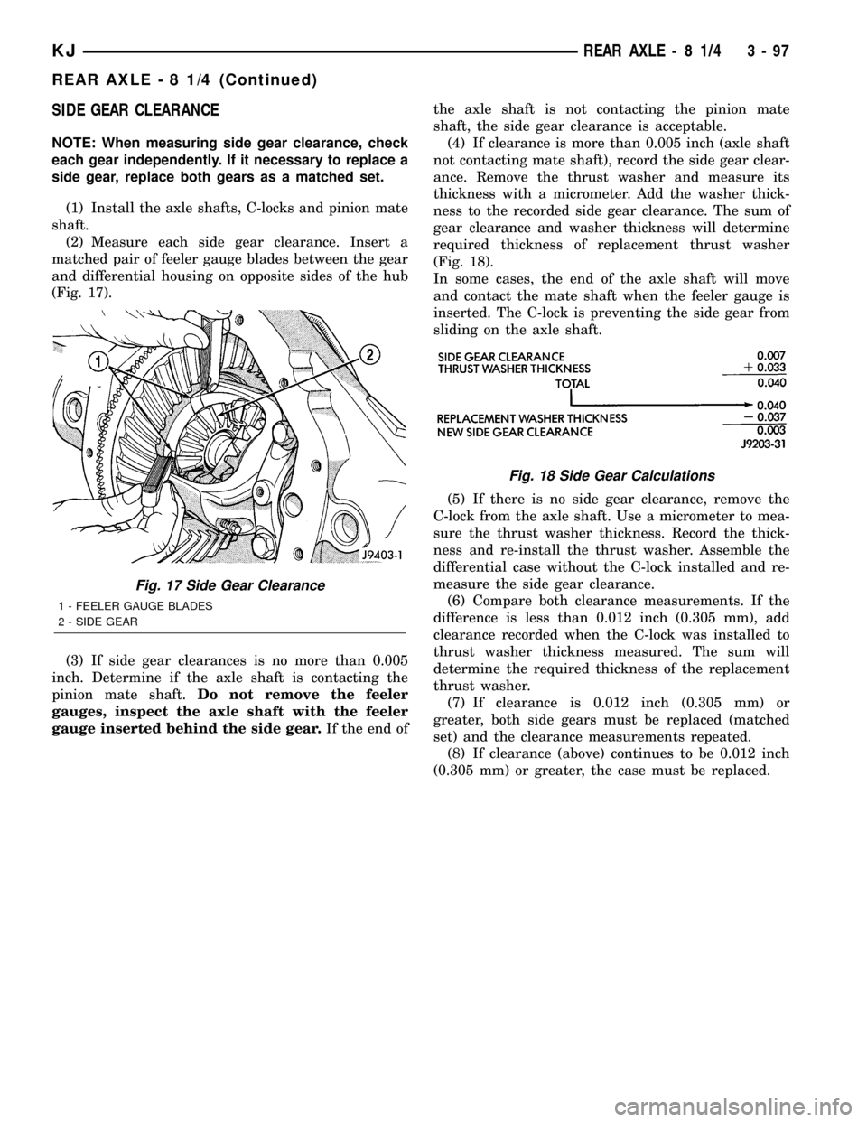
(2) Measure each side gear clearance. Insert a
matched pair of feeler gauge blades between the gear
and differential housing on opposite sides of the hub
(Fig. 17).
(3) If side gear clearances is no more than 0.005
inch. Determine if the axle shaft is contacting the
pinion mate shaft.Do not remove the feeler
gauges, inspect the axle shaft with the feeler
gauge inserted behind the side gear.If the end ofthe axle shaft is not contacting the pinion mate
shaft, the side gear clearance is acceptable.
(4) If clearance is more than 0.005 inch (axle shaft
not contacting mate shaft), record the side gear clear-
ance. Remove the thrust washer and measure its
thickness with a micrometer. Add the washer thick-
ness to the recorded side gear clearance. The sum of
gear clearance and washer thickness will determine
required thickness of replacement thrust washer
(Fig. 18).
In some cases, the end of the axle shaft will move
and contact the mate shaft when the feeler gauge is
inserted. The C-lock is preventing the side gear from
sliding on the axle shaft.
(5) If there is no side gear clearance, remove the
C-lock from the axle shaft. Use a micrometer to mea-
sure the thrust washer thickness. Record the thick-
ness and re-install the thrust washer. Assemble the
differential case without the C-lock installed and re-
measure the side gear clearance.
(6) Compare both clearance measurements. If the
difference is less than 0.012 inch (0.305 mm), add
clearance recorded when the C-lock was installed to
thrust washer thickness measured. The sum will
determine the required thickness of the replacement
thrust washer.
(7) If clearance is 0.012 inch (0.305 mm) or
greater, both side gears must be replaced (matched
set) and the clearance measurements repeated.
(8) If clearance (above) continues to be 0.012 inch
(0.305 mm) or greater, the case must be replaced.
Fig. 17 Side Gear Clearance
1 - FEELER GAUGE BLADES
2 - SIDE GEAR
Fig. 18 Side Gear Calculations
KJREAR AXLE - 8 1/4 3 - 97
REAR AXLE - 8 1/4 (Continued)
Page 176 of 1803
Examine the lining contact pattern to determine if
the shoes are bent or the drum is tapered. The lining
should exhibit contact across its entire width. Shoes
exhibiting contact only on one side should be
replaced and the drum checked for runout or taper.
Inspect the adjuster screw assembly. Replace the
assembly if the star wheel or threads are damaged,
or the components are severely rusted or corroded.
Discard the brake springs and retainer components
if worn, distorted or collapsed. Also replace the
springs if a brake drag condition had occurred. Over-
heating will distort and weaken the springs.
Inspect the brake shoe contact pads on the support
plate, replace the support plate if any of the pads are
worn or rusted through. Also replace the plate if it is
bent or distorted.
(1) Clean support plate with brake cleaner.
(2) If new drums are being installed, remove pro-
tective coating with carburetor cleaner followed by
final rinse with brake cleaner.
(3) Clean and lubricate anchor pin with light coat
of Mopar multi-mileage grease.
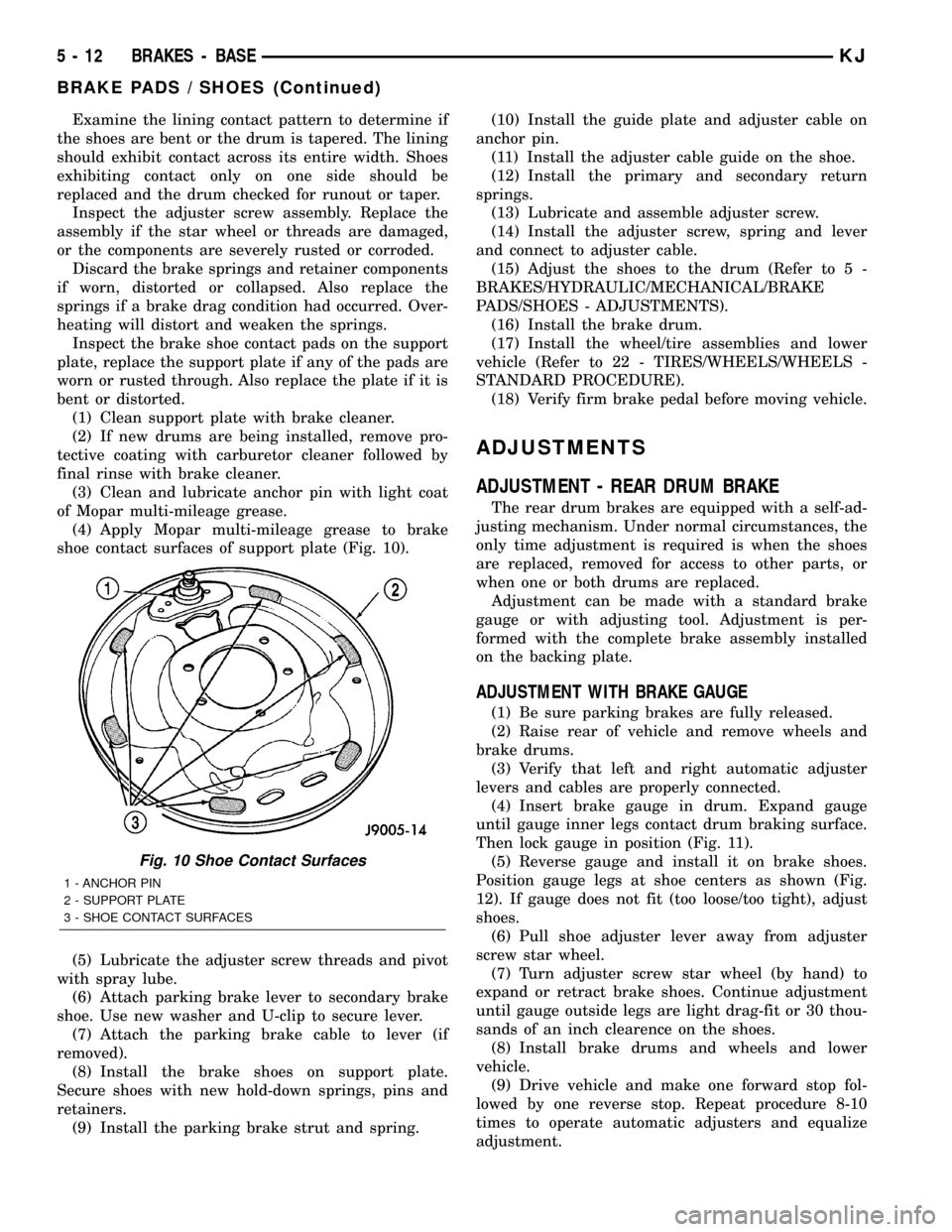
(4) Apply Mopar multi-mileage grease to brake
shoe contact surfaces of support plate (Fig. 10).
(5) Lubricate the adjuster screw threads and pivot
with spray lube.
(6) Attach parking brake lever to secondary brake
shoe. Use new washer and U-clip to secure lever.
(7) Attach the parking brake cable to lever (if
removed).
(8) Install the brake shoes on support plate.
Secure shoes with new hold-down springs, pins and
retainers.
(9) Install the parking brake strut and spring.(10) Install the guide plate and adjuster cable on
anchor pin.
(11) Install the adjuster cable guide on the shoe.
(12) Install the primary and secondary return
springs.
(13) Lubricate and assemble adjuster screw.
(14) Install the adjuster screw, spring and lever
and connect to adjuster cable.
(15) Adjust the shoes to the drum (Refer to 5 -
BRAKES/HYDRAULIC/MECHANICAL/BRAKE
PADS/SHOES - ADJUSTMENTS).
(16) Install the brake drum.
(17) Install the wheel/tire assemblies and lower
vehicle (Refer to 22 - TIRES/WHEELS/WHEELS -
STANDARD PROCEDURE).
(18) Verify firm brake pedal before moving vehicle.
ADJUSTMENTS
ADJUSTMENT - REAR DRUM BRAKE
The rear drum brakes are equipped with a self-ad-
justing mechanism. Under normal circumstances, the
only time adjustment is required is when the shoes
are replaced, removed for access to other parts, or
when one or both drums are replaced.
Adjustment can be made with a standard brake
gauge or with adjusting tool. Adjustment is per-
formed with the complete brake assembly installed
on the backing plate.
ADJUSTMENT WITH BRAKE GAUGE
(1) Be sure parking brakes are fully released.
(2) Raise rear of vehicle and remove wheels and
brake drums.
(3) Verify that left and right automatic adjuster
levers and cables are properly connected.
(4) Insert brake gauge in drum. Expand gauge
until gauge inner legs contact drum braking surface.
Then lock gauge in position (Fig. 11).
(5) Reverse gauge and install it on brake shoes.
Position gauge legs at shoe centers as shown (Fig.
12). If gauge does not fit (too loose/too tight), adjust
shoes.
(6) Pull shoe adjuster lever away from adjuster
screw star wheel.
(7) Turn adjuster screw star wheel (by hand) to
expand or retract brake shoes. Continue adjustment
until gauge outside legs are light drag-fit or 30 thou-
sands of an inch clearence on the shoes.
(8) Install brake drums and wheels and lower
vehicle.
(9) Drive vehicle and make one forward stop fol-
lowed by one reverse stop. Repeat procedure 8-10
times to operate automatic adjusters and equalize
adjustment.
Fig. 10 Shoe Contact Surfaces
1 - ANCHOR PIN
2 - SUPPORT PLATE
3 - SHOE CONTACT SURFACES
5 - 12 BRAKES - BASEKJ
BRAKE PADS / SHOES (Continued)