checking oil JEEP LIBERTY 2002 KJ / 1.G Workshop Manual
[x] Cancel search | Manufacturer: JEEP, Model Year: 2002, Model line: LIBERTY, Model: JEEP LIBERTY 2002 KJ / 1.GPages: 1803, PDF Size: 62.3 MB
Page 14 of 1803
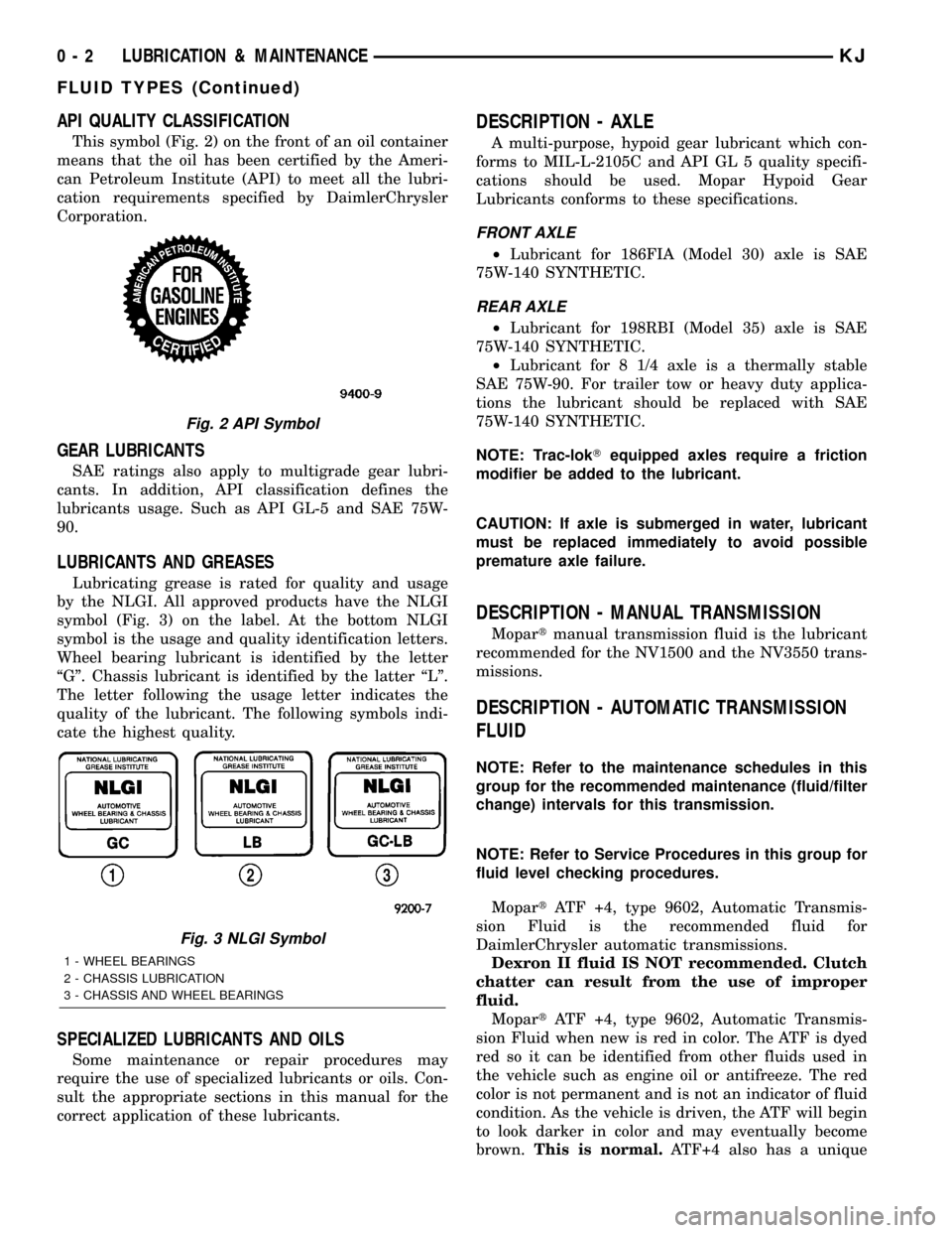
API QUALITY CLASSIFICATION
This symbol (Fig. 2) on the front of an oil container
means that the oil has been certified by the Ameri-
can Petroleum Institute (API) to meet all the lubri-
cation requirements specified by DaimlerChrysler
Corporation.
GEAR LUBRICANTS
SAE ratings also apply to multigrade gear lubri-
cants. In addition, API classification defines the
lubricants usage. Such as API GL-5 and SAE 75W-
90.
LUBRICANTS AND GREASES
Lubricating grease is rated for quality and usage
by the NLGI. All approved products have the NLGI
symbol (Fig. 3) on the label. At the bottom NLGI
symbol is the usage and quality identification letters.
Wheel bearing lubricant is identified by the letter
ªGº. Chassis lubricant is identified by the latter ªLº.
The letter following the usage letter indicates the
quality of the lubricant. The following symbols indi-
cate the highest quality.
SPECIALIZED LUBRICANTS AND OILS
Some maintenance or repair procedures may
require the use of specialized lubricants or oils. Con-
sult the appropriate sections in this manual for the
correct application of these lubricants.
DESCRIPTION - AXLE
A multi-purpose, hypoid gear lubricant which con-
forms to MIL-L-2105C and API GL 5 quality specifi-
cations should be used. Mopar Hypoid Gear
Lubricants conforms to these specifications.
FRONT AXLE
²Lubricant for 186FIA (Model 30) axle is SAE
75W-140 SYNTHETIC.
REAR AXLE
²Lubricant for 198RBI (Model 35) axle is SAE
75W-140 SYNTHETIC.
²Lubricant for 8 1/4 axle is a thermally stable
SAE 75W-90. For trailer tow or heavy duty applica-
tions the lubricant should be replaced with SAE
75W-140 SYNTHETIC.
NOTE: Trac-lokTequipped axles require a friction
modifier be added to the lubricant.
CAUTION: If axle is submerged in water, lubricant
must be replaced immediately to avoid possible
premature axle failure.
DESCRIPTION - MANUAL TRANSMISSION
Mopartmanual transmission fluid is the lubricant
recommended for the NV1500 and the NV3550 trans-
missions.
DESCRIPTION - AUTOMATIC TRANSMISSION
FLUID
NOTE: Refer to the maintenance schedules in this
group for the recommended maintenance (fluid/filter
change) intervals for this transmission.
NOTE: Refer to Service Procedures in this group for
fluid level checking procedures.
MopartATF +4, type 9602, Automatic Transmis-
sion Fluid is the recommended fluid for
DaimlerChrysler automatic transmissions.
Dexron II fluid IS NOT recommended. Clutch
chatter can result from the use of improper
fluid.
MopartATF +4, type 9602, Automatic Transmis-
sion Fluid when new is red in color. The ATF is dyed
red so it can be identified from other fluids used in
the vehicle such as engine oil or antifreeze. The red
color is not permanent and is not an indicator of fluid
condition. As the vehicle is driven, the ATF will begin
to look darker in color and may eventually become
brown.This is normal.ATF+4 also has a unique
Fig. 2 API Symbol
Fig. 3 NLGI Symbol
1 - WHEEL BEARINGS
2 - CHASSIS LUBRICATION
3 - CHASSIS AND WHEEL BEARINGS
0 - 2 LUBRICATION & MAINTENANCEKJ
FLUID TYPES (Continued)
Page 191 of 1803
SPECIFICATIONS
BRAKE FLUID
The brake fluid used in this vehicle must conform
to DOT 3 specifications and SAE J1703 standards.
No other type of brake fluid is recommended or
approved for usage in the vehicle brake system. Use
only Mopar brake fluid or an equivalent from a
tightly sealed container.
CAUTION: Never use reclaimed brake fluid or fluid
from an container which has been left open. An
open container will absorb moisture from the air
and contaminate the fluid.
CAUTION: Never use any type of a petroleum-based
fluid in the brake hydraulic system. Use of such
type fluids will result in seal damage of the vehicle
brake hydraulic system causing a failure of the
vehicle brake system. Petroleum based fluids would
be items such as engine oil, transmission fluid,
power steering fluid, etc.
DRUM
DIAGNOSIS AND TESTING - BRAKE DRUM
The maximum allowable diameter of the drum
braking surface is indicated on the drum outer edge.
Generally, a drum can be machined to a maximum of
1.52 mm (0.060 in.) oversize. Always replace the
drum if machining would cause drum diameter to
exceed the size limit indicated on the drum.
BRAKE DRUM RUNOUT
Measure drum diameter and runout with an accu-
rate gauge. The most accurate method of measure-
ment involves mounting the drum in a brake lathe
and checking variation and runout with a dial indi-
cator.
Variations in drum diameter should not exceed
0.076 mm (0.003 in.). Drum runout should not exceed
0.20 mm (0.008 in.) out of round. Machine the drum
if runout or variation exceed these values. Replace
the drum if machining causes the drum to exceed the
maximum allowable diameter.
STANDARD PROCEDURES - BRAKE DRUM
MACHINING
The brake drums can be machined on a drum lathe
when necessary. Initial machining cuts should be lim-
ited to 0.12 - 0.20 mm (0.005 - 0.008 in.) at a time as
heavier feed rates can produce taper and surface
variation. Final finish cuts of 0.025 to 0.038 mm(0.001 to 0.0015 in.) are recommended and will gen-
erally provide the best surface finish.
Be sure the drum is securely mounted in the lathe
before machining operations. A damper strap should
always be used around the drum to reduce vibration
and avoid chatter marks.
The maximum allowable diameter of the drum
braking surface is stamped or cast into the drum
outer edge.
CAUTION: Replace the drum if machining will cause
the drum to exceed the maximum allowable diame-
ter.
SUPPORT PLATE
REMOVAL
REMOVAL - 198 RBI AXLE
(1) Remove wheel and tire assembly.
(2) Remove the brake drum.
(3) Remove the brake shoes.
(4) Remove parking brake cable from parking
brake lever.
(5) Compress parking brake cable retainer tabs.
Then push retainer and cable through and out of
support plate.
(6) Disconnect brake line at wheel cylinder.
(7) Remove wheel cylinder from support plate,(Re-
fer to 5 - BRAKES/HYDRAULIC/MECHANICAL/
WHEEL CYLINDERS - REMOVAL).
(8) Remove the four bolts attaching the support
plate to axle and remove the support plate with the
axle, bearing and seal.
(9) Remove axle shaft,(Refer to 3 - DIFFEREN-
TIAL & DRIVELINE/REAR AXLE/AXLE SHAFTS -
REMOVAL).
REMOVAL - 8 1/4 AXLE
(1) Remove the wheel and tire assembly.
(2) Remove the brake drum.
(3) Install the brake pedal prop rod.
(4) Remove the brake shoes (Refer to 5 - BRAKES/
HYDRAULIC/MECHANICAL/BRAKE PADS/SHOES
- REMOVAL).
(5) Remove parking brake cable from parking
brake lever.
(6) Compress parking brake cable retainer tabs.
Then push retainer and cable through and out of
support plate.
(7) Disconnect the brake line at wheel cylinder.
(8) Remove the wheel cylinder from the support
plate,(Refer to 5 - BRAKES/HYDRAULIC/MECHAN-
ICAL/WHEEL CYLINDERS - REMOVAL).
KJBRAKES - BASE 5 - 27
FLUID (Continued)
Page 234 of 1803
ENGINE
TABLE OF CONTENTS
page page
COOLANT RECOVERY PRESS CONTAINER
DESCRIPTION.........................19
OPERATION...........................19
ENGINE COOLANT TEMPERATURE SENSOR
DESCRIPTION.........................19
OPERATION...........................20
REMOVAL.............................20
INSTALLATION.........................21
ENGINE COOLANT THERMOSTAT
DESCRIPTION - 3.7L ENGINE.............21
OPERATION...........................21
DIAGNOSIS AND TESTING - THERMOSTAT . . . 21
REMOVAL - 3.7L ENGINE.................21
INSTALLATION - 3.7L ENGINE.............22
RADIATOR
DESCRIPTION.........................22
REMOVAL.............................23
CLEANING............................24
INSPECTION..........................24
INSTALLATION.........................24
RADIATOR PRESSURE CAP
DESCRIPTION.........................25
OPERATION...........................25
DIAGNOSIS AND TESTING - RADIATOR
PRESSURE CAP......................25CLEANING............................25
INSPECTION..........................25
RADIATOR FAN - ELECTRIC
DESCRIPTION.........................26
OPERATION...........................26
REMOVAL.............................26
INSTALLATION.........................27
RADIATOR - FAN - VISCOUS
DESCRIPTION.........................27
OPERATION...........................27
DIAGNOSIS AND TESTING - VISCOUS FAN
DRIVE..............................28
REMOVAL.............................28
CLEANING............................29
INSPECTION..........................29
INSTALLATION.........................29
WATER PUMP
DESCRIPTION
DESCRIPTION - WATER PUMP...........29
DESCRIPTION........................29
OPERATION - WATER PUMP..............30
REMOVAL.............................30
CLEANING............................31
INSPECTION..........................31
INSTALLATION.........................31
COOLANT RECOVERY PRESS
CONTAINER
DESCRIPTION
This system works along with the radiator pres-
sure cap. This is done by using thermal expansion
and contraction of the coolant to keep the coolant
free of trapped air. It provides:
²A volume for coolant expansion and contraction.
²A convenient and safe method for checking/ad-
justing coolant level at atmospheric pressure. This is
done without removing the radiator pressure cap.
²Some reserve coolant to the radiator to cover
minor leaks and evaporation or boiling losses.
As the engine cools, a vacuum is formed in the
cooling system of both the radiator and engine. Cool-
ant will then be drawn from the coolant tank and
returned to a proper level in the radiator.
The coolant reservoir/overflow system has a radia-
tor mounted pressurized cap, an overflow tube, and a
plastic coolant reservoir/overflow tank, mounted to
the right side of the cowl. It is mounted to the cowlwith two nuts on top, and a slide bracket on the bot-
tom.
OPERATION
The pressure chamber keeps the coolant free of
trapped air, provides a volume for expansion and con-
traction, and provides a convenient and safe method
for checking and adjusting coolant level at atmo-
spheric pressure. It also provides some reserve cool-
ant to cover minor leaks, evaporation or boiling
losses. The overflow chamber allows coolant recovery
in case of an overheat.
ENGINE COOLANT
TEMPERATURE SENSOR
DESCRIPTION
The Engine Coolant Temperature (ECT) sensor is
used to sense engine coolant temperature. The sensor
protrudes into an engine water jacket.
KJENGINE 7 - 19
Page 267 of 1803
Propylene-glycol/ethylene-glycol Mixtures can
cause the destabilization of various corrosion inhibi-
tors, causing damage to the various cooling system
components. Also, once ethylene-glycol and propy-
lene-glycol based coolants are mixed in the vehicle,
conventional methods of determining freeze point will
not be accurate. Both the refractive index and spe-
cific gravity differ between ethylene glycol and propy-
lene glycol.
OPERATION
Coolant flows through the engine block absorbing
the heat from the engine, then flows to the radiator
where the cooling fins in the radiator transfers the
heat from the coolant to the atmosphere. During cold
weather the ethylene-glycol coolant prevents water
present in the cooling system from freezing within
temperatures indicated by mixture ratio of coolant to
water.
COOLANT RECOVERY PRESS
CONTAINER
DESCRIPTION
This system works along with the radiator pres-
sure cap. This is done by using thermal expansion
and contraction of the coolant to keep the coolant
free of trapped air. It provides:
²A volume for coolant expansion and contraction.
²A convenient and safe method for checking/ad-
justing coolant level at atmospheric pressure. This is
done without removing the radiator pressure cap.
²Some reserve coolant to the radiator to cover
minor leaks and evaporation or boiling losses.
As the engine cools, a vacuum is formed in the
cooling system of both the radiator and engine. Cool-
ant will then be drawn from the coolant tank and
returned to a proper level in the radiator.
The coolant reservoir/overflow system has a radia-
tor mounted pressurized cap, an overflow tube, and a
plastic coolant reservoir/overflow tank, mounted to
the right side of the cowl. It is mounted to the cowl
with two nuts on top, and a slide bracket on the bot-
tom.
OPERATION
The pressure chamber keeps the coolant free of
trapped air, provides a volume for expansion and con-
traction, and provides a convenient and safe method
for checking and adjusting coolant level at atmo-
spheric pressure. It also provides some reserve cool-
ant to cover minor leaks, evaporation or boiling
losses. The overflow chamber allows coolant recovery
in case of an overheat.
ENGINE BLOCK HEATER - 2.4L
DESCRIPTION
The block heater is operated by ordinary house
current (110 Volt A.C.) through a power cord and con-
nector located in the engine compartment. The
heater is mounted in a core hole (in place of a core
hole plug) in the engine block, with the heating ele-
ment immersed in coolant.
CAUTION: The power cord must be secured in its
retainer clips, and not positioned so it could con-
tact linkages or exhaust manifolds and become
damaged.
OPERATION
The block heater element is submerged in the cool-
ing system's coolant. When electrical power (110 volt
A.C.) is applied to the element, it creates heat. This
heat is transferred to the engine coolant. This pro-
vides easier engine starting and faster warm-up
when vehicle is operated in areas having extremely
low temperatures.
REMOVAL - 2.4L
(1) Drain cooling system (Refer to 7 - COOLING/
ENGINE - STANDARD PROCEDURE).
(2) Raise vehicle on hoist.
(3) Detach power cord plug from heater.
(4) Loosen screw in center of heater. Remove
heater assembly.
INSTALLATION - 2.4L
(1) Thoroughly clean core hole and heater seat.
(2) Insert heater assembly (Fig. 1) with element
loop positionedupward.
(3) With heater seated, tighten center screw
securely to assure a positive seal.
CAUTION: To prevent damage, the power cord must
be secured in it's retaining clips, and not positioned
so it could contact linkages or exhaust manifold.
(4) Connect power cord to heater.
(5) Lower vehicle.
(6) Fill cooling system (Refer to 7 - COOLING/EN-
GINE - STANDARD PROCEDURE).
7s - 20 ENGINEKJ
COOLANT (Continued)
Page 1257 of 1803
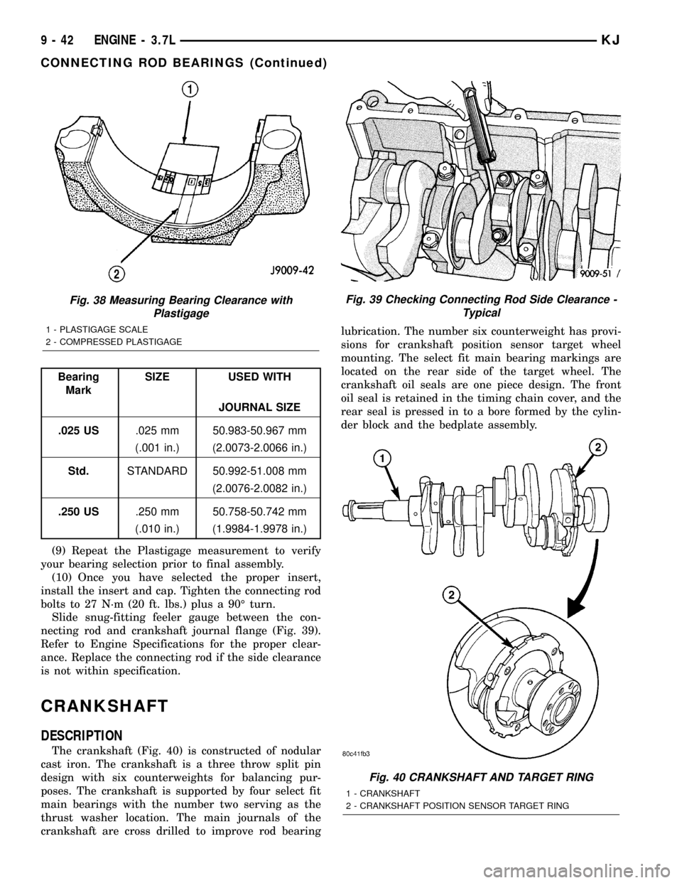
Bearing
MarkSIZE USED WITH
JOURNAL SIZE
.025 US.025 mm 50.983-50.967 mm
(.001 in.) (2.0073-2.0066 in.)
Std.STANDARD 50.992-51.008 mm
(2.0076-2.0082 in.)
.250 US.250 mm 50.758-50.742 mm
(.010 in.) (1.9984-1.9978 in.)
(9) Repeat the Plastigage measurement to verify
your bearing selection prior to final assembly.
(10) Once you have selected the proper insert,
install the insert and cap. Tighten the connecting rod
bolts to 27 N´m (20 ft. lbs.) plus a 90É turn.
Slide snug-fitting feeler gauge between the con-
necting rod and crankshaft journal flange (Fig. 39).
Refer to Engine Specifications for the proper clear-
ance. Replace the connecting rod if the side clearance
is not within specification.
CRANKSHAFT
DESCRIPTION
The crankshaft (Fig. 40) is constructed of nodular
cast iron. The crankshaft is a three throw split pin
design with six counterweights for balancing pur-
poses. The crankshaft is supported by four select fit
main bearings with the number two serving as the
thrust washer location. The main journals of the
crankshaft are cross drilled to improve rod bearinglubrication. The number six counterweight has provi-
sions for crankshaft position sensor target wheel
mounting. The select fit main bearing markings are
located on the rear side of the target wheel. The
crankshaft oil seals are one piece design. The front
oil seal is retained in the timing chain cover, and the
rear seal is pressed in to a bore formed by the cylin-
der block and the bedplate assembly.
Fig. 38 Measuring Bearing Clearance with
Plastigage
1 - PLASTIGAGE SCALE
2 - COMPRESSED PLASTIGAGE
Fig. 39 Checking Connecting Rod Side Clearance -
Typical
Fig. 40 CRANKSHAFT AND TARGET RING
1 - CRANKSHAFT
2 - CRANKSHAFT POSITION SENSOR TARGET RING
9 - 42 ENGINE - 3.7LKJ
CONNECTING ROD BEARINGS (Continued)
Page 1261 of 1803
MAIN BEARING JOURNAL DIAMETER
(CRANKSHAFT REMOVED)
Remove the crankshaft from the cylinder block.
Refer to CRANKSHAFT.
Clean the oil off the main bearing journal.
Determine the maximum diameter of the journal
with a micrometer. Measure at two locations 90É
apart at each end of the journal.
The maximum allowable taper is 0.008mm (0.0004
inch.) and maximum out of round is 0.005mm (0.002
inch). Compare the measured diameter with the jour-
nal diameter specification (Main Bearing Fitting
Chart). Select inserts required to obtain the specified
bearing-to-journal clearance.
Install the crankshaft into the cylinder block. Refer
to CRANKSHAFT.
Check crankshaft end play. Refer to CHECKING
CRANKSHAFT END PLAY.
CRANKSHAFT MAIN BEARING SELECTION
(1) Service main bearings are available in three
grades. The chart below identifies the three service
grades available.
Crankshaft JOURNAL SIZE
SIZE mm (in.)
MARKING
9R9Size 63.488 - 63.496 mm
(2.4995 - 2.4998 in.)
9S9Size
63.496 - 63.500 mm (2.4998 - 2.4999 in.
9T9Size63.500 - 63.504 mm (2.4999 - 2.501 in.)
Bearing size and application
Bearing
CodeSIze Application
Upper Bearing
A.2.443 - 2.447
mmUse with
Cankshaft size9R9
(.0961 - .0963 in.)
B2.439 - 2.443 mm Use with
crankshaft9S, T9
(0.960 -.o961 in.)
C2.435 - 2.439 mm Use with
carnkshaft9U9
(.0958 - .0960 in.)
Lower Bearing Main919and949
9192.441 - 2.447 mm Use with
carnkshaft9R, S9
(.0961 -.0963 in.)
9292.435 - 2.441 mm Use with
crankshaft9T, U9
(.0958 - .0962 in.)
Crankshaft JOURNAL SIZE
SIZE mm (in.)
MARKING
Lower Main Bearing929and939
9392.429 - 2.435 mm Use with
crankshaft9R, S9
(.0956 - .0958 in.)
9492.423 - 2.429 mm Use with
crankshaft9T, U9
(.0953 - .0956 in.)
Bearing Clearances
Main91, 49
Crankshaft
9R9.004 - .034 mm ( .00015 - .0013 in.)
Crankshaft
9S9.004 - .030 mm ( .00015 - .0011 in.)
Crankshaft
9T9.006 - .032 mm (.0002 - .0012 in.)
Crankshaft
9U9.002 - .032 mm (.00007 -. 0012 in.)
Main92, 39
Crankshaft
9R9.016 - .064 mm (.0 062 - .0025 in.)
Crankshaft
9S9.016 - .042 mm (.00062 - .016 in.)
Crankshaft
9T9.018 - .044 mm (.0007 - .0017 in.)
Crankshaft
9U9.014 - .044 mm (.0005 - .0017 in.)
CRANKSHAFT OIL SEAL -
FRONT
REMOVAL
(1) Disconnect negative cable from battery.
(2) Remove accessory drive belt (Refer to 7 -
COOLING/ACCESSORY DRIVE/DRIVE BELTS -
REMOVAL).
(3) Remove A/C compressor mouning fasteners and
set aside.
(4) Drain cooling system (Refer to 7 - COOLING -
STANDARD PROCEDURE).
(5) Remove upper radiator hose.
(6) Disconnect electrical connector for fan mounted
inside radiator shroud.
(7) Remove radiator shroud attaching fasteners.
(8) Remove radiator cooling fan and shroud (Refer
to 7 - COOLING/ENGINE/RADIATOR FAN -
REMOVAL).
(9) Remove crankshaft damper bolt.
9 - 46 ENGINE - 3.7LKJ
CRANKSHAFT MAIN BEARINGS (Continued)
Page 1277 of 1803
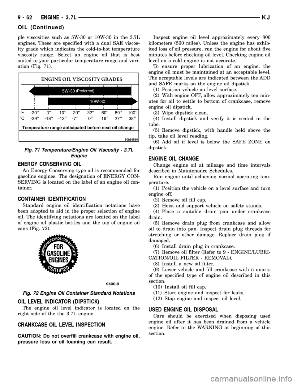
ple viscosities such as 5W-30 or 10W-30 in the 3.7L
engines. These are specified with a dual SAE viscos-
ity grade which indicates the cold-to-hot temperature
viscosity range. Select an engine oil that is best
suited to your particular temperature range and vari-
ation (Fig. 71).
ENERGY CONSERVING OIL
An Energy Conserving type oil is recommended for
gasoline engines. The designation of ENERGY CON-
SERVING is located on the label of an engine oil con-
tainer.
CONTAINER IDENTIFICATION
Standard engine oil identification notations have
been adopted to aid in the proper selection of engine
oil. The identifying notations are located on the label
of engine oil plastic bottles and the top of engine oil
cans (Fig. 72).
OIL LEVEL INDICATOR (DIPSTICK)
The engine oil level indicator is located on the
right side of the the 3.7L engine.
CRANKCASE OIL LEVEL INSPECTION
CAUTION: Do not overfill crankcase with engine oil,
pressure loss or oil foaming can result.Inspect engine oil level approximately every 800
kilometers (500 miles). Unless the engine has exhib-
ited loss of oil pressure, run the engine for about five
minutes before checking oil level. Checking engine oil
level on a cold engine is not accurate.
To ensure proper lubrication of an engine, the
engine oil must be maintained at an acceptable level.
The acceptable levels are indicated between the ADD
and SAFE marks on the engine oil dipstick.
(1) Position vehicle on level surface.
(2) With engine OFF, allow approximately ten min-
utes for oil to settle to bottom of crankcase, remove
engine oil dipstick.
(3) Wipe dipstick clean.
(4) Install dipstick and verify it is seated in the
tube.
(5) Remove dipstick, with handle held above the
tip, take oil level reading.
(6) Add oil if level is below the SAFE ZONE on
dipstick.
ENGINE OIL CHANGE
Change engine oil at mileage and time intervals
described in Maintenance Schedules.
Run engine until achieving normal operating tem-
perature.
(1) Position the vehicle on a level surface and turn
engine off.
(2) Remove oil fill cap.
(3) Hoist and support vehicle on safety stands.
(4) Place a suitable drain pan under crankcase
drain.
(5) Remove drain plug from crankcase and allow
oil to drain into pan. Inspect drain plug threads for
stretching or other damage. Replace drain plug if
damaged.
(6) Install drain plug in crankcase.
(7) Remove oil filter (Refer to 9 - ENGINE/LUBRI-
CATION/OIL FILTER - REMOVAL).
(8) Install a new oil filter.
(9) Lower vehicle and fill crankcase with 5 quarts
of the specified type of engine oil described in this
section.
(10) Install oil fill cap.
(11) Start engine and inspect for leaks.
(12) Stop engine and inspect oil level.
USED ENGINE OIL DISPOSAL
Care should be exercised when disposing used
engine oil after it has been drained from a vehicle
engine. Refer to the WARNING at beginning of this
section.
Fig. 71 Temperature/Engine Oil Viscosity - 3.7L
Engine
Fig. 72 Engine Oil Container Standard Notations
9 - 62 ENGINE - 3.7LKJ
OIL (Continued)
Page 1281 of 1803
INSPECTION
CAUTION: Oil pump pressure relief valve and
spring should not be removed from the oil pump. If
these components are disassembled and or
removed from the pump the entire oil pump assem-
bly must be replaced.
(1) Clean all parts thoroughly. Mating surface of
the oil pump housing should be smooth. If the pump
cover is scratched or grooved the oil pump assembly
should be replaced.
(2) Lay a straight edge across the pump cover sur-
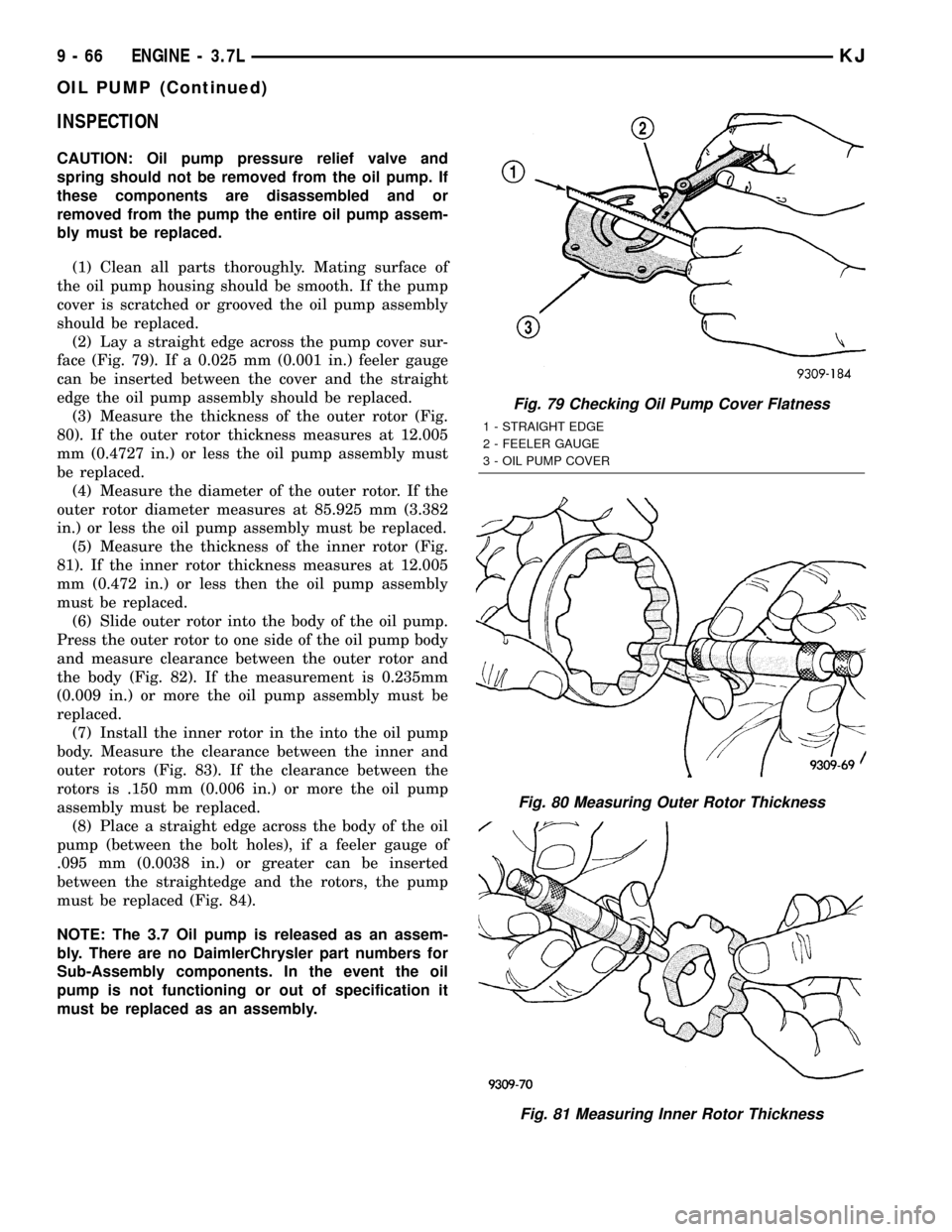
face (Fig. 79). If a 0.025 mm (0.001 in.) feeler gauge
can be inserted between the cover and the straight
edge the oil pump assembly should be replaced.
(3) Measure the thickness of the outer rotor (Fig.
80). If the outer rotor thickness measures at 12.005
mm (0.4727 in.) or less the oil pump assembly must
be replaced.
(4) Measure the diameter of the outer rotor. If the
outer rotor diameter measures at 85.925 mm (3.382
in.) or less the oil pump assembly must be replaced.
(5) Measure the thickness of the inner rotor (Fig.
81). If the inner rotor thickness measures at 12.005
mm (0.472 in.) or less then the oil pump assembly
must be replaced.
(6) Slide outer rotor into the body of the oil pump.
Press the outer rotor to one side of the oil pump body
and measure clearance between the outer rotor and
the body (Fig. 82). If the measurement is 0.235mm
(0.009 in.) or more the oil pump assembly must be
replaced.
(7) Install the inner rotor in the into the oil pump
body. Measure the clearance between the inner and
outer rotors (Fig. 83). If the clearance between the
rotors is .150 mm (0.006 in.) or more the oil pump
assembly must be replaced.
(8) Place a straight edge across the body of the oil
pump (between the bolt holes), if a feeler gauge of
.095 mm (0.0038 in.) or greater can be inserted
between the straightedge and the rotors, the pump
must be replaced (Fig. 84).
NOTE: The 3.7 Oil pump is released as an assem-
bly. There are no DaimlerChrysler part numbers for
Sub-Assembly components. In the event the oil
pump is not functioning or out of specification it
must be replaced as an assembly.
Fig. 79 Checking Oil Pump Cover Flatness
1 - STRAIGHT EDGE
2 - FEELER GAUGE
3 - OIL PUMP COVER
Fig. 80 Measuring Outer Rotor Thickness
Fig. 81 Measuring Inner Rotor Thickness
9 - 66 ENGINE - 3.7LKJ
OIL PUMP (Continued)
Page 1299 of 1803
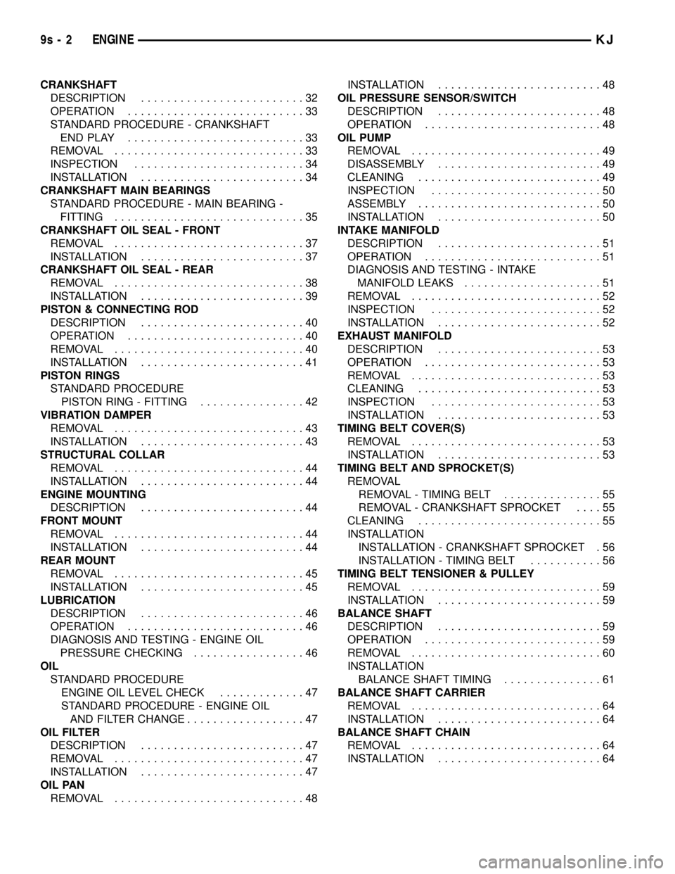
CRANKSHAFT
DESCRIPTION.........................32
OPERATION...........................33
STANDARD PROCEDURE - CRANKSHAFT
ENDPLAY ...........................33
REMOVAL.............................33
INSPECTION..........................34
INSTALLATION.........................34
CRANKSHAFT MAIN BEARINGS
STANDARD PROCEDURE - MAIN BEARING -
FITTING.............................35
CRANKSHAFT OIL SEAL - FRONT
REMOVAL.............................37
INSTALLATION.........................37
CRANKSHAFT OIL SEAL - REAR
REMOVAL.............................38
INSTALLATION.........................39
PISTON & CONNECTING ROD
DESCRIPTION.........................40
OPERATION...........................40
REMOVAL.............................40
INSTALLATION.........................41
PISTON RINGS
STANDARD PROCEDURE
PISTON RING - FITTING................42
VIBRATION DAMPER
REMOVAL.............................43
INSTALLATION.........................43
STRUCTURAL COLLAR
REMOVAL.............................44
INSTALLATION.........................44
ENGINE MOUNTING
DESCRIPTION.........................44
FRONT MOUNT
REMOVAL.............................44
INSTALLATION.........................44
REAR MOUNT
REMOVAL.............................45
INSTALLATION.........................45
LUBRICATION
DESCRIPTION.........................46
OPERATION...........................46
DIAGNOSIS AND TESTING - ENGINE OIL
PRESSURE CHECKING.................46
OIL
STANDARD PROCEDURE
ENGINE OIL LEVEL CHECK.............47
STANDARD PROCEDURE - ENGINE OIL
AND FILTER CHANGE..................47
OIL FILTER
DESCRIPTION.........................47
REMOVAL.............................47
INSTALLATION.........................47
OIL PAN
REMOVAL.............................48INSTALLATION.........................48
OIL PRESSURE SENSOR/SWITCH
DESCRIPTION.........................48
OPERATION...........................48
OIL PUMP
REMOVAL.............................49
DISASSEMBLY.........................49
CLEANING............................49
INSPECTION..........................50
ASSEMBLY............................50
INSTALLATION.........................50
INTAKE MANIFOLD
DESCRIPTION.........................51
OPERATION...........................51
DIAGNOSIS AND TESTING - INTAKE
MANIFOLD LEAKS.....................51
REMOVAL.............................52
INSPECTION..........................52
INSTALLATION.........................52
EXHAUST MANIFOLD
DESCRIPTION.........................53
OPERATION...........................53
REMOVAL.............................53
CLEANING............................53
INSPECTION..........................53
INSTALLATION.........................53
TIMING BELT COVER(S)
REMOVAL.............................53
INSTALLATION.........................53
TIMING BELT AND SPROCKET(S)
REMOVAL
REMOVAL - TIMING BELT...............55
REMOVAL - CRANKSHAFT SPROCKET....55
CLEANING............................55
INSTALLATION
INSTALLATION - CRANKSHAFT SPROCKET . 56
INSTALLATION - TIMING BELT...........56
TIMING BELT TENSIONER & PULLEY
REMOVAL.............................59
INSTALLATION.........................59
BALANCE SHAFT
DESCRIPTION.........................59
OPERATION...........................59
REMOVAL.............................60
INSTALLATION
BALANCE SHAFT TIMING...............61
BALANCE SHAFT CARRIER
REMOVAL.............................64
INSTALLATION.........................64
BALANCE SHAFT CHAIN
REMOVAL.............................64
INSTALLATION.........................64
9s - 2 ENGINEKJ
Page 1309 of 1803
NOTE: Plastigage is available in a variety of clear-
ance ranges. Use the most appropriate range for
the specifications you are checking.
(4) Install the proper crankshaft bearings to
achieve the specified bearing clearances. (Refer to 9 -
ENGINE/ENGINE BLOCK/CRANKSHAFT MAIN
BEARINGS - STANDARD PROCEDURE) (Refer to 9
- ENGINE/ENGINE BLOCK/CONNECTING ROD
BEARINGS - STANDARD PROCEDURE)
REMOVAL - ENGINE ASSEMBLY
(1) Disconnect the battery negative cable.
(2) Remove hood. Mark hood hinge location for
reinstallation.
(3) Remove air cleaner assembly.
(4) Remove radiator core support bracket.
(5) Remove fan shroud with electric fan assembly.
(6) Remove drive belt.
NOTE: It is NOT necessary to discharge the A/C
system to remove the engine.
(7) Remove A/C compressor and secure away from
engine with lines attached.
(8) Remove generator and secure away from
engine.
NOTE: Do NOT remove the phenolic pulley from the
P/S pump. It is not required for P/S pump removal.
(9) Remove power steering pump with lines
attached and secure away from engine.
(10) Drain cooling system.
(11) Remove coolant bottle.
(12) Disconnect the heater hoses from the engine.
(13) Disconnect heater hoses from heater core and
remove hose assembly.
(14) Disconnect throttle and speed control cables.
(15) Remove upper radiator hose from engine.
(16) Remove lower radiator hose from engine.
(17) Disconnect the engine to body ground straps
at the left side of cowl.
(18) Disconnect the engine wiring harness at the
following points:
²Intake air temperature (IAT) sensor
²Fuel Injectors
²Throttle Position (TPS) Switch
²Idle Air Control (IAC) Motor
²Engine Oil Pressure Switch
²Engine Coolant Temperature (ECT) Sensor
²Manifold Absolute Pressure MAP) Sensor
²Camshaft Position (CMP) Sensor
²Coil Over Plugs
²Crankshaft Position Sensor
(19) Remove coil over plugs.
(20) Release fuel rail pressure.(21) Remove fuel rail and secure away from
engine.
(22) Remove the PCV hose.
(23) Remove the breather hoses.
(24) Remove the vacuum hose for the power brake
booster.
(25) Disconnect knock sensors.
(26) Secure the left and right engine wiring har-
nesses away from engine.
(27) Raise vehicle.
(28) Disconnect oxygen sensor wiring.
(29) Disconnect crankshaft postion sensor.
(30) Disconnect the engine block heater power
cable, if equipped.
(31) Disconnect the front propshaft at the front
differential and secure out of way.
(32) Remove the starter.
(33) Remove the ground straps from the engine
(34) Disconnect the exhaust pipes at the manifold.
(35) Remove the structural cover, if equipped.
(36) Remove torque convertor bolts, and mark
location for reassembly.
(37) Remove transmission bellhousing to engine
bolts.
(38) Loosen left and right engine mount thru bolts.
NOTE: It is not necessary to completely remove
engine mount thru bolts, for engine removal.
(39) Lower the vehicle.
(40) Support the transmission with a suitable jack.
(41) Connect a suitable engine hoist to the engine.
CAUTION: The 2.4L engine with manual transmis-
sions, can be removed without removing the man-
ual transmission. Use caution when attempting this
procedure as the clearance is tight.
(42) Remove engine from vehicle.
INSTALLATION - ENGINE ASSEMBLY
(1) Position the engine in the vehicle.
CAUTION: Use caution when installing 2.4L engine
into vehicle equipped with manual transmission, as
clearance is tight.
(2) Install both left and right side engine mounts
into the frame mounts.
(3) Raise the vehicle.
(4) Install the transmission bellhousing to engine
mounting bolts. Tighten the bolts to 41 N´m (30ft.
lbs.).
(5) Tighten the engine mount thru bolts.
(6) Install the torque convertor bolts.
(7) Connect the ground straps on the left and right
side of the engine.
9s - 12 ENGINEKJ
ENGINE - 2.4L (Continued)