coolant level JEEP LIBERTY 2002 KJ / 1.G Workshop Manual
[x] Cancel search | Manufacturer: JEEP, Model Year: 2002, Model line: LIBERTY, Model: JEEP LIBERTY 2002 KJ / 1.GPages: 1803, PDF Size: 62.3 MB
Page 16 of 1803
centage of antifreeze can cause the engine to over-
heat because specific heat of antifreeze is lower than
that of water.
CAUTION: Richer antifreeze mixtures cannot be
measured with normal field equipment and can
cause problems associated with 100 percent ethyl-
ene-glycol.
CAUTION: Do not use coolant additives that are
claimed to improve engine cooling.
OPERATION - AUTOMATIC TRANSMISSION
FLUID
The automatic transmission fluid is selected based
upon several qualities. The fluid must provide a high
level of protection for the internal components by
providing a lubricating film between adjacent metal
components. The fluid must also be thermally stable
so that it can maintain a consistent viscosity through
a large temperature range. If the viscosity stays con-
stant through the temperature range of operation,
transmission operation and shift feel will remain con-
sistent. Transmission fluid must also be a good con-
ductor of heat. The fluid must absorb heat from the
internal transmission components and transfer that
heat to the transmission case.
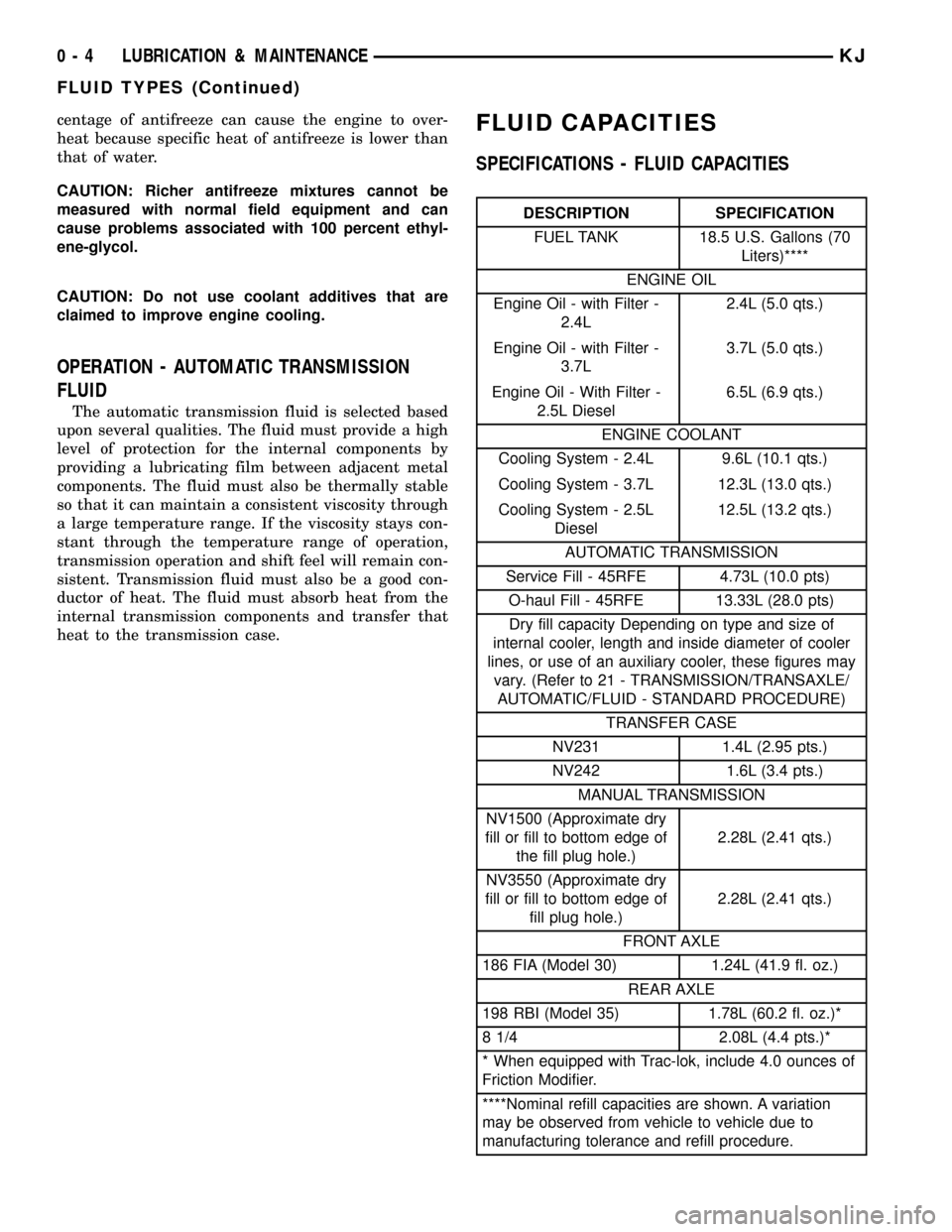
FLUID CAPACITIES
SPECIFICATIONS - FLUID CAPACITIES
DESCRIPTION SPECIFICATION
FUEL TANK 18.5 U.S. Gallons (70
Liters)****
ENGINE OIL
Engine Oil - with Filter -
2.4L2.4L (5.0 qts.)
Engine Oil - with Filter -
3.7L3.7L (5.0 qts.)
Engine Oil - With Filter -
2.5L Diesel6.5L (6.9 qts.)
ENGINE COOLANT
Cooling System - 2.4L 9.6L (10.1 qts.)
Cooling System - 3.7L 12.3L (13.0 qts.)
Cooling System - 2.5L
Diesel12.5L (13.2 qts.)
AUTOMATIC TRANSMISSION
Service Fill - 45RFE 4.73L (10.0 pts)
O-haul Fill - 45RFE 13.33L (28.0 pts)
Dry fill capacity Depending on type and size of
internal cooler, length and inside diameter of cooler
lines, or use of an auxiliary cooler, these figures may
vary. (Refer to 21 - TRANSMISSION/TRANSAXLE/
AUTOMATIC/FLUID - STANDARD PROCEDURE)
TRANSFER CASE
NV231 1.4L (2.95 pts.)
NV242 1.6L (3.4 pts.)
MANUAL TRANSMISSION
NV1500 (Approximate dry
fill or fill to bottom edge of
the fill plug hole.)2.28L (2.41 qts.)
NV3550 (Approximate dry
fill or fill to bottom edge of
fill plug hole.)2.28L (2.41 qts.)
FRONT AXLE
186 FIA (Model 30) 1.24L (41.9 fl. oz.)
REAR AXLE
198 RBI (Model 35) 1.78L (60.2 fl. oz.)*
8 1/4 2.08L (4.4 pts.)*
* When equipped with Trac-lok, include 4.0 ounces of
Friction Modifier.
****Nominal refill capacities are shown. A variation
may be observed from vehicle to vehicle due to
manufacturing tolerance and refill procedure.
0 - 4 LUBRICATION & MAINTENANCEKJ
FLUID TYPES (Continued)
Page 219 of 1803

DIAGNOSIS AND TESTING - COOLING SYSTEM
LEAKS
ULTRAVIOLET LIGHT METHOD
A leak detection additive is available through the
parts department that can be added to cooling sys-
tem. The additive is highly visible under ultraviolet
light (black light). Pour one ounce of additive into
cooling system. Place heater control unit in HEAT
position. Start and operate engine until radiator
upper hose is warm to touch. Aim the commercially
available black light tool at components to be
checked. If leaks are present, black light will cause
additive to glow a bright green color.
The black light can be used in conjunction with a
pressure tester to determine if any external leaks
exist (Fig. 3).
PRESSURE TESTER METHOD
The engine should be at normal operating temper-
ature. Recheck the system cold if cause of coolant
loss is not located during the warm engine examina-
tion.
WARNING: HOT, PRESSURIZED COOLANT CAN
CAUSE INJURY BY SCALDING.
Carefully remove radiator pressure cap from pres-
sure bottle and check coolant level. Push down on
cap to disengage it from stop tabs. Wipe inside of
filler neck and examine lower inside sealing seat fornicks, cracks, paint, and dirt. Inspect radiator-to-
reserve/overflow tank hose for internal obstructions.
Insert a wire through the hose to be sure it is not
obstructed.
Inspect cams on outside of filler neck. If cams are
damaged, seating of pressure cap valve and tester
seal will be affected.
Attach pressure tester (7700 or an equivalent) to
radiator filler neck (Fig. 4).
Operate tester pump to apply 110 kPa (16 psi)
pressure to system. If hoses enlarge excessively or
bulges while testing, replace as necessary. Observe
gauge pointer and determine condition of cooling sys-
tem according to following criteria:
Holds Steady:If pointer remains steady for two
minutes, serious coolant leaks are not present in sys-
tem. However, there could be an internal leak that
does not appear with normal system test pressure. If
it is certain that coolant is being lost and leaks can-
not be detected, inspect for interior leakage or per-
form Internal Leakage Test.
Drops Slowly:Indicates a small leak or seepage
is occurring. Examine all connections for seepage or
slight leakage with a flashlight. Inspect radiator,
hoses, gasket edges and heater. Seal small leak holes
with a Sealer Lubricant (or equivalent). Repair leak
holes and inspect system again with pressure
applied.
Drops Quickly:Indicates that serious leakage is
occurring. Examine system for external leakage. If
leaks are not visible, inspect for internal leakage.
Large radiator leak holes should be repaired by a
reputable radiator repair shop.
INTERNAL LEAKAGE INSPECTION
Remove engine oil pan drain plug and drain a
small amount of engine oil. If coolant is present in
Fig. 3 Leak Detection Using Black Light - Typical
1 - TYPICAL BLACK LIGHT TOOL
Fig. 4 Pressure Testing Cooling System - Typical
1 - TYPICAL COOLING SYSTEM PRESSURE TESTER
7 - 4 COOLINGKJ
COOLING (Continued)
Page 220 of 1803

the pan, it will drain first because it is heavier than
oil. An alternative method is to operate engine for a
short period to churn the oil. After this is done,
remove engine dipstick and inspect for water glob-
ules. Also inspect transmission dipstick for water
globules and transmission fluid cooler for leakage.
WARNING: WITH RADIATOR PRESSURE TESTER
TOOL INSTALLED ON RADIATOR, DO NOT ALLOW
PRESSURE TO EXCEED 124 KPA (18 PSI). PRES-
SURE WILL BUILD UP QUICKLY IF A COMBUSTION
LEAK IS PRESENT. TO RELEASE PRESSURE,
ROCK TESTER FROM SIDE TO SIDE. WHEN
REMOVING TESTER, DO NOT TURN TESTER MORE
THAN 1/2 TURN IF SYSTEM IS UNDER PRESSURE.
Operate engine without pressure cap on radiator
until thermostat opens. Attach a Pressure Tester to
filler neck. If pressure builds up quickly it indicates a
combustion leak exists. This is usually the result of a
cylinder head gasket leak or crack in engine. Repair
as necessary.
If there is not an immediate pressure increase,
pump the Pressure Tester. Do this until indicated
pressure is within system range of 110 kPa (16 psi).
Fluctuation of gauge pointer indicates compression or
combustion leakage into cooling system.
Because the vehicle is equipped with a catalytic
converter,do notremove spark plug cables or short
out cylinders to isolate compression leak.
If the needle on dial of pressure tester does not
fluctuate, race engine a few times to check for an
abnormal amount of coolant or steam. This would be
emitting from exhaust pipe. Coolant or steam from
exhaust pipe may indicate a faulty cylinder head gas-
ket, cracked engine cylinder block or cylinder head.A convenient check for exhaust gas leakage into
cooling system is provided by a commercially avail-
able Block Leak Check tool. Follow manufacturers
instructions when using this product.
COMBUSTION LEAKAGE TEST - WITHOUT
PRESSURE TESTER
DO NOT WASTE reusable coolant. If solution is
clean, drain coolant into a clean container for reuse.
WARNING: DO NOT REMOVE CYLINDER BLOCK
DRAIN PLUGS OR LOOSEN RADIATOR DRAIN-
COCK WITH SYSTEM HOT AND UNDER PRESSURE.
SERIOUS BURNS FROM COOLANT CAN OCCUR.
Drain sufficient coolant to allow thermostat
removal. (Refer to 7 - COOLING/ENGINE/ENGINE
COOLANT THERMOSTAT - REMOVAL). Remove
accessory drive belt (Refer to 7 - COOLING/ACCES-
SORY DRIVE/DRIVE BELTS - REMOVAL).
Add coolant to radiator to bring level to within 6.3
mm (1/4 in) of top of thermostat housing.
CAUTION: Avoid overheating. Do not operate
engine for an excessive period of time. Open drain-
cock immediately after test to eliminate boil over.
Start engine and accelerate rapidly three times, to
approximately 3000 rpm while observing coolant. If
internal engine combustion gases are leaking into
cooling system, bubbles will appear in coolant. If bub-
bles do not appear, internal combustion gas leakage
is not present.
KJCOOLING 7 - 5
COOLING (Continued)
Page 221 of 1803
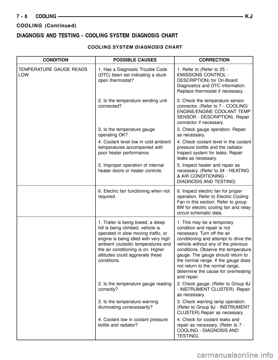
DIAGNOSIS AND TESTING - COOLING SYSTEM DIAGNOSIS CHART
COOLING SYSTEM DIAGNOSIS CHART
CONDITION POSSIBLE CAUSES CORRECTION
TEMPERATURE GAUGE READS
LOW1. Has a Diagnostic Trouble Code
(DTC) been set indicating a stuck
open thermostat?1. Refer to (Refer to 25 -
EMISSIONS CONTROL -
DESCRIPTION) for On-Board
Diagnostics and DTC information.
Replace thermostat if necessary.
2. Is the temperature sending unit
connected?2. Check the temperature sensor
connector. (Refer to 7 - COOLING/
ENGINE/ENGINE COOLANT TEMP
SENSOR - DESCRIPTION). Repair
connector if necessary.
3. Is the temperature gauge
operating OK?3. Check gauge operation. Repair
as necessary.
4. Coolant level low in cold ambient
temperatures accompanied with
poor heater performance.4. Check coolant level in the coolant
pressure botttle and the radiator.
Inspect system for leaks. Repair
leaks as necessary.
5. Improper operation of internal
heater doors or heater controls.5. Inspect heater and repair as
necessary. (Refer to 24 - HEATING
& AIR CONDITIONING -
DIAGNOSIS AND TESTING)
6. Electric fan functioning when not
required.6. Inspect electric fan for proper
operation. Refer to Electric Cooling
Fan in this section. Refer to group
8W for electric cooling fan and relay
circuit schematic data.
1. Trailer is being towed, a steep
hill is being climbed, vehicle is
operated in slow moving traffic, or
engine is being idled with very high
ambient (outside) temperatures and
the air conditioning is on. Higher
altitudes could aggravate these
conditions.1. This may be a temporary
condition and repair is not
necessary. Turn off the air
conditioning and attempt to drive the
vehicle without any of the previous
conditions. Observe the temperature
gauge. The gauge should return to
the normal range. If the gauge does
not return to the normal range,
determine the cause for overheating
and repair.
2. Is the temperature gauge reading
correctly?2. Check gauge. (Refer to Group 8J
- INSTRUMENT CLUSTER). Repair
as necessary.
3. Is the temperature warning
illuminating unnecessarily?3. Check warning lamp operation.
(Refer to Group 8J - INSTRUMENT
CLUSTER).Repair as necessary.
4. Coolant low in coolant pressure
bottle and radiator?4. Check for coolant leaks and
repair as necessary. (Refer to 7 -
COOLING - DIAGNOSIS AND
TESTING).
7 - 6 COOLINGKJ
COOLING (Continued)
Page 223 of 1803
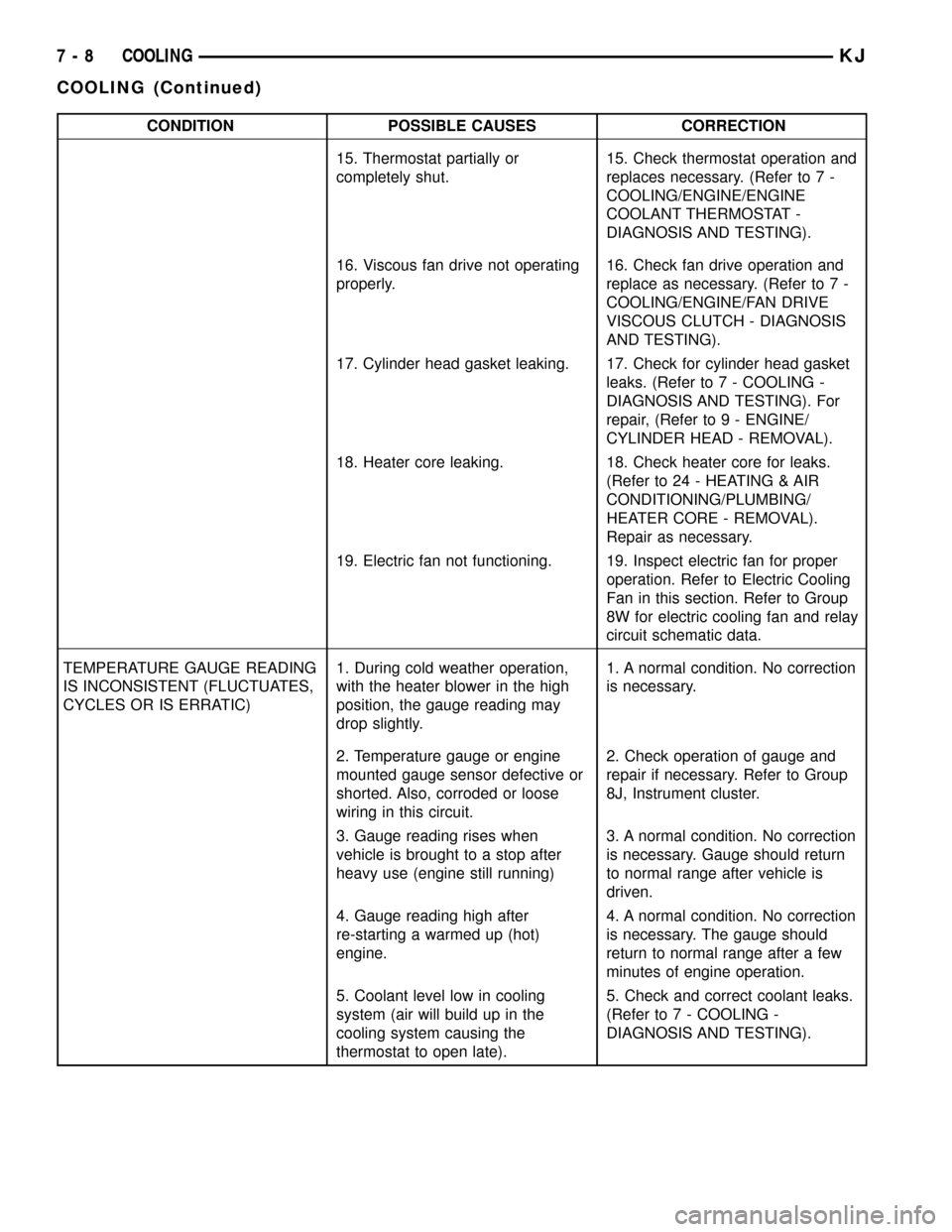
CONDITION POSSIBLE CAUSES CORRECTION
15. Thermostat partially or
completely shut.15. Check thermostat operation and
replaces necessary. (Refer to 7 -
COOLING/ENGINE/ENGINE
COOLANT THERMOSTAT -
DIAGNOSIS AND TESTING).
16. Viscous fan drive not operating
properly.16. Check fan drive operation and
replace as necessary. (Refer to 7 -
COOLING/ENGINE/FAN DRIVE
VISCOUS CLUTCH - DIAGNOSIS
AND TESTING).
17. Cylinder head gasket leaking. 17. Check for cylinder head gasket
leaks. (Refer to 7 - COOLING -
DIAGNOSIS AND TESTING). For
repair, (Refer to 9 - ENGINE/
CYLINDER HEAD - REMOVAL).
18. Heater core leaking. 18. Check heater core for leaks.
(Refer to 24 - HEATING & AIR
CONDITIONING/PLUMBING/
HEATER CORE - REMOVAL).
Repair as necessary.
19. Electric fan not functioning. 19. Inspect electric fan for proper
operation. Refer to Electric Cooling
Fan in this section. Refer to Group
8W for electric cooling fan and relay
circuit schematic data.
TEMPERATURE GAUGE READING
IS INCONSISTENT (FLUCTUATES,
CYCLES OR IS ERRATIC)1. During cold weather operation,
with the heater blower in the high
position, the gauge reading may
drop slightly.1. A normal condition. No correction
is necessary.
2. Temperature gauge or engine
mounted gauge sensor defective or
shorted. Also, corroded or loose
wiring in this circuit.2. Check operation of gauge and
repair if necessary. Refer to Group
8J, Instrument cluster.
3. Gauge reading rises when
vehicle is brought to a stop after
heavy use (engine still running)3. A normal condition. No correction
is necessary. Gauge should return
to normal range after vehicle is
driven.
4. Gauge reading high after
re-starting a warmed up (hot)
engine.4. A normal condition. No correction
is necessary. The gauge should
return to normal range after a few
minutes of engine operation.
5. Coolant level low in cooling
system (air will build up in the
cooling system causing the
thermostat to open late).5. Check and correct coolant leaks.
(Refer to 7 - COOLING -
DIAGNOSIS AND TESTING).
7 - 8 COOLINGKJ
COOLING (Continued)
Page 224 of 1803
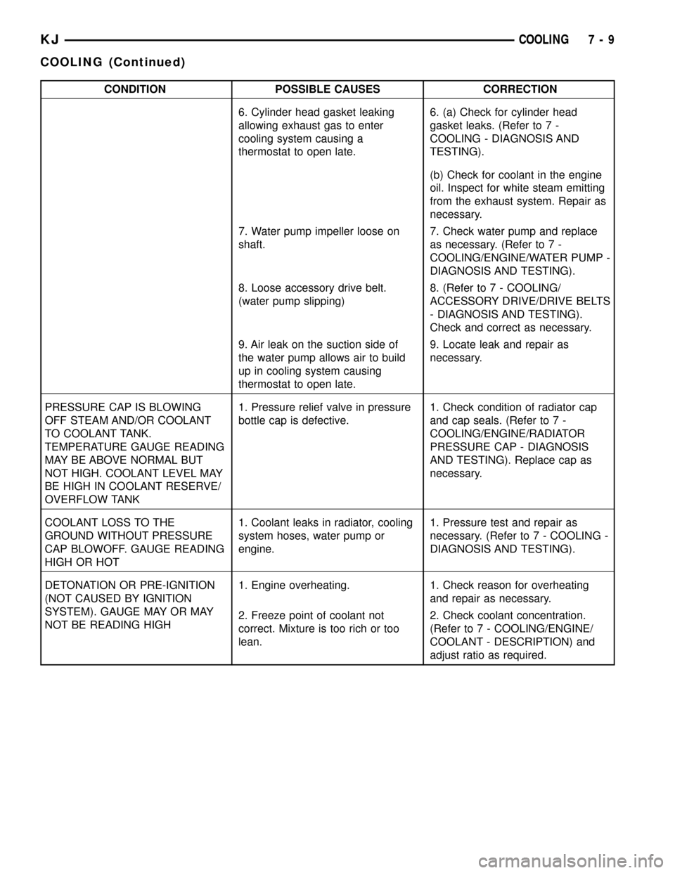
CONDITION POSSIBLE CAUSES CORRECTION
6. Cylinder head gasket leaking
allowing exhaust gas to enter
cooling system causing a
thermostat to open late.6. (a) Check for cylinder head
gasket leaks. (Refer to 7 -
COOLING - DIAGNOSIS AND
TESTING).
(b) Check for coolant in the engine
oil. Inspect for white steam emitting
from the exhaust system. Repair as
necessary.
7. Water pump impeller loose on
shaft.7. Check water pump and replace
as necessary. (Refer to 7 -
COOLING/ENGINE/WATER PUMP -
DIAGNOSIS AND TESTING).
8. Loose accessory drive belt.
(water pump slipping)8. (Refer to 7 - COOLING/
ACCESSORY DRIVE/DRIVE BELTS
- DIAGNOSIS AND TESTING).
Check and correct as necessary.
9. Air leak on the suction side of
the water pump allows air to build
up in cooling system causing
thermostat to open late.9. Locate leak and repair as
necessary.
PRESSURE CAP IS BLOWING
OFF STEAM AND/OR COOLANT
TO COOLANT TANK.
TEMPERATURE GAUGE READING
MAY BE ABOVE NORMAL BUT
NOT HIGH. COOLANT LEVEL MAY
BE HIGH IN COOLANT RESERVE/
OVERFLOW TANK1. Pressure relief valve in pressure
bottle cap is defective.1. Check condition of radiator cap
and cap seals. (Refer to 7 -
COOLING/ENGINE/RADIATOR
PRESSURE CAP - DIAGNOSIS
AND TESTING). Replace cap as
necessary.
COOLANT LOSS TO THE
GROUND WITHOUT PRESSURE
CAP BLOWOFF. GAUGE READING
HIGH OR HOT1. Coolant leaks in radiator, cooling
system hoses, water pump or
engine.1. Pressure test and repair as
necessary. (Refer to 7 - COOLING -
DIAGNOSIS AND TESTING).
DETONATION OR PRE-IGNITION
(NOT CAUSED BY IGNITION
SYSTEM). GAUGE MAY OR MAY
NOT BE READING HIGH1. Engine overheating. 1. Check reason for overheating
and repair as necessary.
2. Freeze point of coolant not
correct. Mixture is too rich or too
lean.2. Check coolant concentration.
(Refer to 7 - COOLING/ENGINE/
COOLANT - DESCRIPTION) and
adjust ratio as required.
KJCOOLING 7 - 9
COOLING (Continued)
Page 225 of 1803
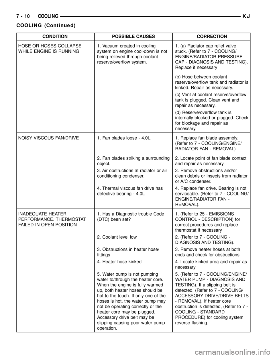
CONDITION POSSIBLE CAUSES CORRECTION
HOSE OR HOSES COLLAPSE
WHILE ENGINE IS RUNNING1. Vacuum created in cooling
system on engine cool-down is not
being relieved through coolant
reserve/overflow system.1. (a) Radiator cap relief valve
stuck. (Refer to 7 - COOLING/
ENGINE/RADIATOR PRESSURE
CAP - DIAGNOSIS AND TESTING).
Replace if necessary
(b) Hose between coolant
reserve/overflow tank and radiator is
kinked. Repair as necessary.
(c) Vent at coolant reserve/overflow
tank is plugged. Clean vent and
repair as necessary.
(d) Reserve/overflow tank is
internally blocked or plugged. Check
for blockage and repair as
necessary.
NOISY VISCOUS FAN/DRIVE 1. Fan blades loose - 4.0L. 1. Replace fan blade assembly.
(Refer to 7 - COOLING/ENGINE/
RADIATOR FAN - REMOVAL)
2. Fan blades striking a surrounding
object.2. Locate point of fan blade contact
and repair as necessary.
3. Air obstructions at radiator or air
conditioning condenser.3. Remove obstructions and/or
clean debris or insects from radiator
or A/C condenser.
4. Thermal viscous fan drive has
defective bearing - 4.0L4. Replace fan drive. Bearing is not
serviceable. (Refer to 7 - COOLING/
ENGINE/RADIATOR FAN -
REMOVAL).
INADEQUATE HEATER
PERFORMANCE. THERMOSTAT
FAILED IN OPEN POSITION1. Has a Diagnostic trouble Code
(DTC) been set?1. (Refer to 25 - EMISSIONS
CONTROL - DESCRIPTION) for
correct procedures and replace
thermostat if necessary
2. Coolant level low 2. (Refer to 7 - COOLING -
DIAGNOSIS AND TESTING).
3. Obstructions in heater hose/
fittings3. Remove heater hoses at both
ends and check for obstructions
4. Heater hose kinked 4. Locate kinked area and repair as
necessary
5. Water pump is not pumping
water to/through the heater core.
When the engine is fully warmed
up, both heater hoses should be
hot to the touch. If only one of the
hoses is hot, the water pump may
not be operating correctly or the
heater core may be plugged.
Accessory drive belt may be
slipping causing poor water pump
operation.5. (Refer to 7 - COOLING/ENGINE/
WATER PUMP - DIAGNOSIS AND
TESTING). If a slipping belt is
detected, (Refer to 7 - COOLING/
ACCESSORY DRIVE/DRIVE BELTS
- REMOVAL). If heater core
obstruction is detected, (Refer to 7 -
COOLING - STANDARD
PROCEDURE) for cooling system
reverse flushing.
7 - 10 COOLINGKJ
COOLING (Continued)
Page 226 of 1803
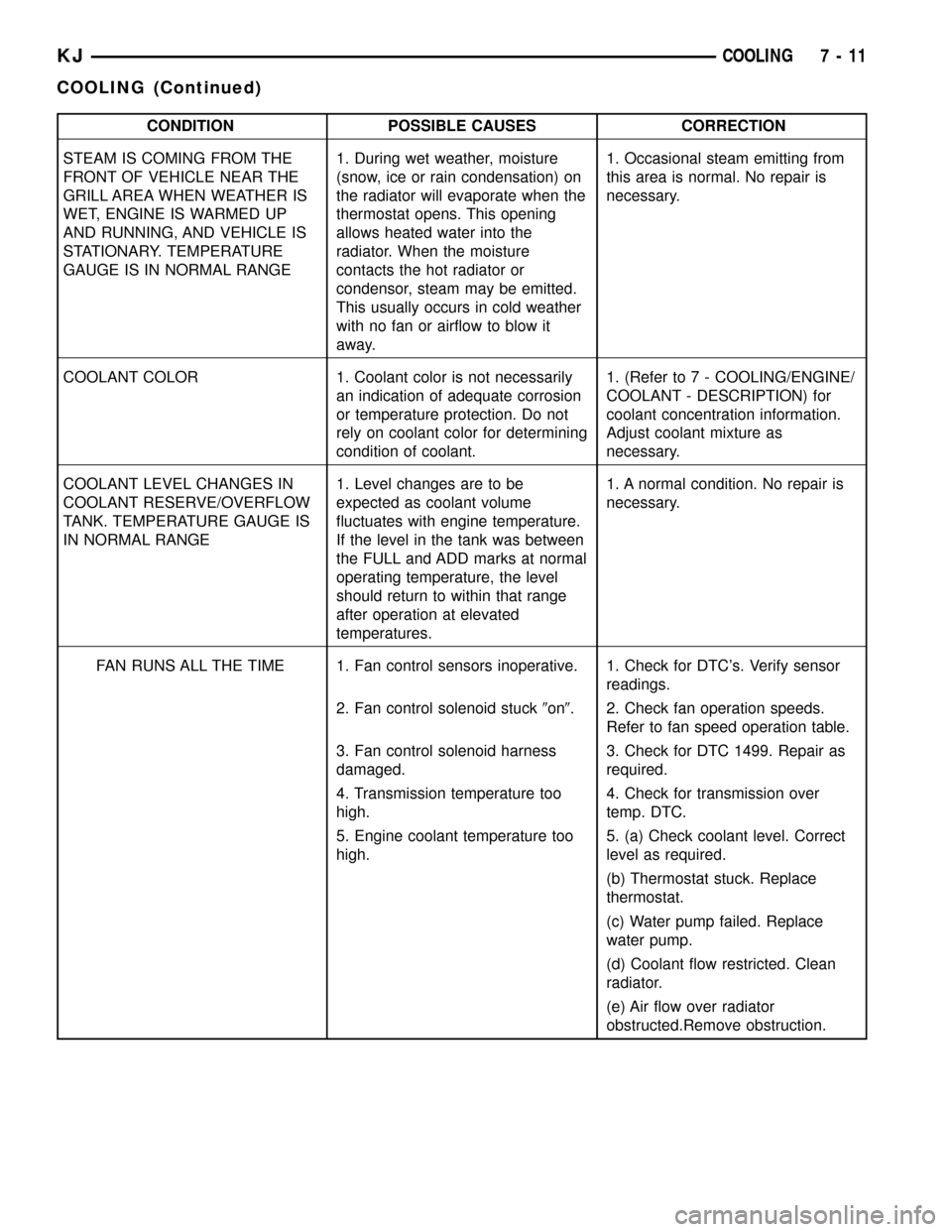
CONDITION POSSIBLE CAUSES CORRECTION
STEAM IS COMING FROM THE
FRONT OF VEHICLE NEAR THE
GRILL AREA WHEN WEATHER IS
WET, ENGINE IS WARMED UP
AND RUNNING, AND VEHICLE IS
STATIONARY. TEMPERATURE
GAUGE IS IN NORMAL RANGE1. During wet weather, moisture
(snow, ice or rain condensation) on
the radiator will evaporate when the
thermostat opens. This opening
allows heated water into the
radiator. When the moisture
contacts the hot radiator or
condensor, steam may be emitted.
This usually occurs in cold weather
with no fan or airflow to blow it
away.1. Occasional steam emitting from
this area is normal. No repair is
necessary.
COOLANT COLOR 1. Coolant color is not necessarily
an indication of adequate corrosion
or temperature protection. Do not
rely on coolant color for determining
condition of coolant.1. (Refer to 7 - COOLING/ENGINE/
COOLANT - DESCRIPTION) for
coolant concentration information.
Adjust coolant mixture as
necessary.
COOLANT LEVEL CHANGES IN
COOLANT RESERVE/OVERFLOW
TANK. TEMPERATURE GAUGE IS
IN NORMAL RANGE1. Level changes are to be
expected as coolant volume
fluctuates with engine temperature.
If the level in the tank was between
the FULL and ADD marks at normal
operating temperature, the level
should return to within that range
after operation at elevated
temperatures.1. A normal condition. No repair is
necessary.
FAN RUNS ALL THE TIME 1. Fan control sensors inoperative. 1. Check for DTC's. Verify sensor
readings.
2. Fan control solenoid stuck9on9. 2. Check fan operation speeds.
Refer to fan speed operation table.
3. Fan control solenoid harness
damaged.3. Check for DTC 1499. Repair as
required.
4. Transmission temperature too
high.4. Check for transmission over
temp. DTC.
5. Engine coolant temperature too
high.5. (a) Check coolant level. Correct
level as required.
(b) Thermostat stuck. Replace
thermostat.
(c) Water pump failed. Replace
water pump.
(d) Coolant flow restricted. Clean
radiator.
(e) Air flow over radiator
obstructed.Remove obstruction.
KJCOOLING 7 - 11
COOLING (Continued)
Page 227 of 1803

STANDARD PROCEDURE
STANDARD PROCEDURE - DRAINING COOLING
SYSTEM 3.7L ENGINE
WARNING: DO NOT REMOVE THE CYLINDER
BLOCK DRAIN PLUGS (Fig. 5) OR LOOSEN THE
RADIATOR DRAINCOCK WITH SYSTEM HOT AND
UNDER PRESSURE. SERIOUS BURNS FROM
COOLANT CAN OCCUR.
(1) DO NOT remove radiator cap first. With engine
cold, raise vehicle on a hoist and locate radiator
draincock.
NOTE: Radiator draincock is located on the left/
lower side of radiator facing to rear of vehicle.
(2) Attach one end of a hose to the draincock. Put
the other end into a clean container. Open draincock
and drain coolant from radiator. This will empty the
coolant reserve/overflow tank. The coolant does not
have to be removed from the tank unless the system
is being refilled with a fresh mixture. When tank is
empty, remove radiator cap and continue draining
cooling system.
STANDARD PROCEDURE - REFILLING
COOLING SYSTEM 3.7L ENGINE
(1) Tighten the radiator draincock and the cylinder
block drain plug(s) (if removed).CAUTION: Failure to purge air from the cooling sys-
tem can result in an overheating condition and
severe engine damage.
(2) .Fill system using a 50/50 mixture of ethylene-
glycol antifreeze and low mineral content water.Fill
pressure bottle to service line.and install cap.
NOTE: The engine cooling system will push any
remaining air into the coolant bottle within about an
hour of normal driving. As a result, a drop in cool-
ant level in the pressure bottle may occur. If the
engine cooling system overheats and pushes cool-
ant into the overflow side of the coolant bottle, this
coolant will be sucked back into the cooling system
ONLY IF THE PRESSURE CAP IS LEFT ON THE
BOTTLE. Removing the pressure cap breaks the
vacuum path between the two bottle sections and
the coolant will not return to cooling system.
(3) With heater control unit in the HEAT position,
operate engine with pressure bottle cap in place.
(4) Add coolant to pressure bottle as necessary.
Only add coolant to the pressure bottle when
the engine is cold. Coolant level in a warm
engine will be higher due to thermal expansion.
NOTE: The coolant bottle has two chambers. Cool-
ant will normally only be in the outboard (larger) of
the two. The inboard chamber is only to recover
coolant in the event of an overheat or after a recent
service fill. The inboard chamber should normally
be empty. If there is coolant in the overflow side of
the coolant bottle (after several warm/cold cycles of
the engine) and coolant level is above cold full
when cold, disconnect the end of the overflow hose
at the fill neck and lower it into a clean container.
Allow coolant to drain into the container until emp-
tied. Reconnect overflow hose to fill neck.
STANDARD PROCEDURE - COOLING SYSTEM -
REVERSE FLUSHING
CAUTION: The cooling system normally operates at
97-to-110 kPa (14-to -16 psi) pressure. Exceeding
this pressure may damage the radiator or hoses.
Reverse flushing of the cooling system is the forc-
ing of water through the cooling system. This is done
using air pressure in the opposite direction of normal
coolant flow. It is usually only necessary with very
dirty systems with evidence of partial plugging.
CHEMICAL CLEANING
If visual inspection indicates the formation of
sludge or scaly deposits, use a radiator cleaner
Fig. 5 Drain Plug - 3.7L Engine
1 - CYLINDER BLOCK DRAIN PLUG
2 - EXHAUST MANIFOLD AND HEAT SHIELD
7 - 12 COOLINGKJ
COOLING (Continued)
Page 234 of 1803

ENGINE
TABLE OF CONTENTS
page page
COOLANT RECOVERY PRESS CONTAINER
DESCRIPTION.........................19
OPERATION...........................19
ENGINE COOLANT TEMPERATURE SENSOR
DESCRIPTION.........................19
OPERATION...........................20
REMOVAL.............................20
INSTALLATION.........................21
ENGINE COOLANT THERMOSTAT
DESCRIPTION - 3.7L ENGINE.............21
OPERATION...........................21
DIAGNOSIS AND TESTING - THERMOSTAT . . . 21
REMOVAL - 3.7L ENGINE.................21
INSTALLATION - 3.7L ENGINE.............22
RADIATOR
DESCRIPTION.........................22
REMOVAL.............................23
CLEANING............................24
INSPECTION..........................24
INSTALLATION.........................24
RADIATOR PRESSURE CAP
DESCRIPTION.........................25
OPERATION...........................25
DIAGNOSIS AND TESTING - RADIATOR
PRESSURE CAP......................25CLEANING............................25
INSPECTION..........................25
RADIATOR FAN - ELECTRIC
DESCRIPTION.........................26
OPERATION...........................26
REMOVAL.............................26
INSTALLATION.........................27
RADIATOR - FAN - VISCOUS
DESCRIPTION.........................27
OPERATION...........................27
DIAGNOSIS AND TESTING - VISCOUS FAN
DRIVE..............................28
REMOVAL.............................28
CLEANING............................29
INSPECTION..........................29
INSTALLATION.........................29
WATER PUMP
DESCRIPTION
DESCRIPTION - WATER PUMP...........29
DESCRIPTION........................29
OPERATION - WATER PUMP..............30
REMOVAL.............................30
CLEANING............................31
INSPECTION..........................31
INSTALLATION.........................31
COOLANT RECOVERY PRESS
CONTAINER
DESCRIPTION
This system works along with the radiator pres-
sure cap. This is done by using thermal expansion
and contraction of the coolant to keep the coolant
free of trapped air. It provides:
²A volume for coolant expansion and contraction.
²A convenient and safe method for checking/ad-
justing coolant level at atmospheric pressure. This is
done without removing the radiator pressure cap.
²Some reserve coolant to the radiator to cover
minor leaks and evaporation or boiling losses.
As the engine cools, a vacuum is formed in the
cooling system of both the radiator and engine. Cool-
ant will then be drawn from the coolant tank and
returned to a proper level in the radiator.
The coolant reservoir/overflow system has a radia-
tor mounted pressurized cap, an overflow tube, and a
plastic coolant reservoir/overflow tank, mounted to
the right side of the cowl. It is mounted to the cowlwith two nuts on top, and a slide bracket on the bot-
tom.
OPERATION
The pressure chamber keeps the coolant free of
trapped air, provides a volume for expansion and con-
traction, and provides a convenient and safe method
for checking and adjusting coolant level at atmo-
spheric pressure. It also provides some reserve cool-
ant to cover minor leaks, evaporation or boiling
losses. The overflow chamber allows coolant recovery
in case of an overheat.
ENGINE COOLANT
TEMPERATURE SENSOR
DESCRIPTION
The Engine Coolant Temperature (ECT) sensor is
used to sense engine coolant temperature. The sensor
protrudes into an engine water jacket.
KJENGINE 7 - 19