torque JEEP LIBERTY 2002 KJ / 1.G Workshop Manual
[x] Cancel search | Manufacturer: JEEP, Model Year: 2002, Model line: LIBERTY, Model: JEEP LIBERTY 2002 KJ / 1.GPages: 1803, PDF Size: 62.3 MB
Page 2 of 1803
FOREWORD
This manual is designed as a supplement to be used along with the 2002 Liberty service manual,
81-370-02060. It includes information related to the 2.4L gas engine installed in this vehicle by
DaimlerChrysler Corporation. For diagnosis or service procedures relating to other components or systems,
refer to the 2002 Liberty Service Manual.
The information contained in this service manual has been prepared for the professional automotive tech-
nician involved in daily repair operations. Information describing the operation and use of standard and
optional equipment is included in the Owner's Manual provided with the vehicle.
Information in this manual is divided into groups. These groups contain description, operation, diagnosis,
testing, adjustments, removal, installation, disassembly, and assembly procedures for the systems and compo-
nents. To assist in locating a group title page, use the Group Tab Locator on the following page. The solid bar
after the group title is aligned to a solid tab on the first page of each group. The first page of the group has
a contents section that lists major topics within the group. If you are not sure which Group contains the infor-
mation you need, look up the Component/System in the alphabetical index located in the rear of this manual.
A Service Manual Comment form is included at the rear of this manual. Use the form to provide
DaimlerChrysler Corporation with your comments and suggestions.
Tightening torques are provided as a specific value throughout this manual. This value represents the
midpoint of the acceptable engineering torque range for a given fastener application. These torque values are
intended for use in service assembly and installation procedures using the correct OEM fasteners. When
replacing fasteners, always use the same type (part number) fastener as removed.
DaimlerChrysler Corporation reserves the right to change testing procedures, specifications, diagnosis,
repair methods, or vehicle wiring at any time without prior notice or incurring obligation.
Page 4 of 1803
INTRODUCTION
TABLE OF CONTENTS
page page
FASTENER IDENTIFICATION
DESCRIPTION..........................1
FASTENER USAGE
DESCRIPTION
DESCRIPTION........................4
DESCRIPTION........................4
THREADED HOLE REPAIR
DESCRIPTION..........................4
INTERNATIONAL SYMBOLS
DESCRIPTION..........................4
METRIC SYSTEM
DESCRIPTION..........................5TORQUE REFERENCES
DESCRIPTION..........................7
VEHICLE EMISSION CONTROL INFORMATION
(VECI) LABEL
DESCRIPTION..........................8
VEHICLE IDENTIFICATION NUMBER
DESCRIPTION..........................8
VEHICLE SAFETY CERTIFICATION LABEL
DESCRIPTION..........................9
FASTENER IDENTIFICATION
DESCRIPTION
The SAE bolt strength grades range from grade 2
to grade 8. The higher the grade number, the greater
the bolt strength. Identification is determined by the
line marks on the top of each bolt head. The actual
bolt strength grade corresponds to the number of linemarks plus 2. The most commonly used metric bolt
strength classes are 9.8 and 10.9. The metric
strength class identification number is imprinted on
the head of the bolt. The higher the class number,
the greater the bolt strength. Some metric nuts are
imprinted with a single-digit strength class on the
nut face. Refer to the Fastener Identification and
Fastener Strength Charts (Fig. 1) and (Fig. 2).
KJINTRODUCTION 1
Page 7 of 1803
FASTENER USAGE
DESCRIPTION
DESCRIPTION
WARNING: USE OF AN INCORRECT FASTENER
MAY RESULT IN COMPONENT DAMAGE OR PER-
SONAL INJURY.
Figure art, specifications and torque references in
this Service Manual are identified in metric and SAE
format.
During any maintenance or repair procedures, it is
important to salvage all fasteners (nuts, bolts, etc.)
for reassembly. If the fastener is not salvageable, a
fastener of equivalent specification must be used.
DESCRIPTION
Most stripped threaded holes can be repaired using
a Helicoilt. Follow the vehicle or Helicoiltrecommen-
dations for application and repair procedures.
THREADED HOLE REPAIR
DESCRIPTION
Most stripped threaded holes can be repaired using
a Helicoilt. Follow the vehicle or Helicoiltrecommen-
dations for application and repair procedures.
INTERNATIONAL SYMBOLS
DESCRIPTION
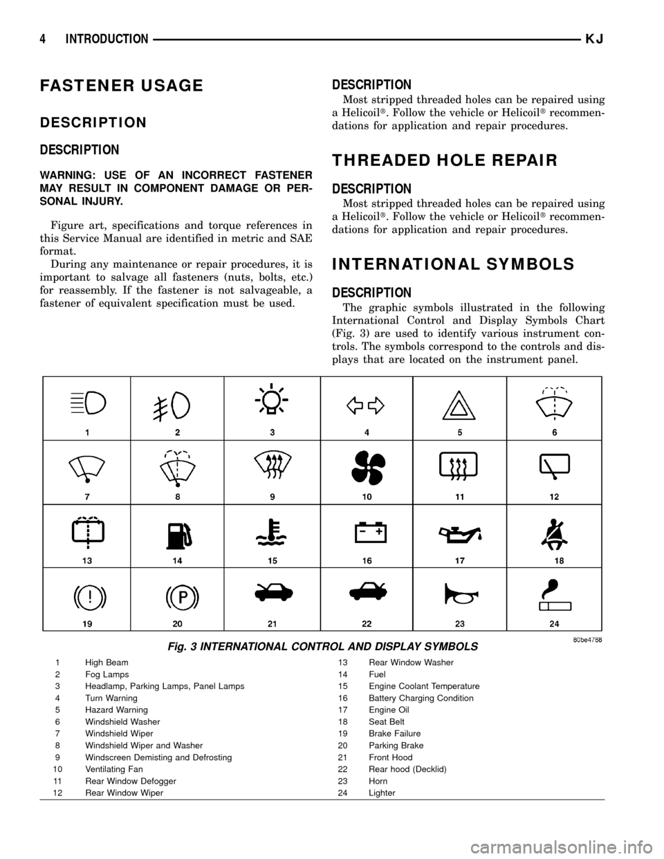
The graphic symbols illustrated in the following
International Control and Display Symbols Chart
(Fig. 3) are used to identify various instrument con-
trols. The symbols correspond to the controls and dis-
plays that are located on the instrument panel.
Fig. 3 INTERNATIONAL CONTROL AND DISPLAY SYMBOLS
1 High Beam 13 Rear Window Washer
2 Fog Lamps 14 Fuel
3 Headlamp, Parking Lamps, Panel Lamps 15 Engine Coolant Temperature
4 Turn Warning 16 Battery Charging Condition
5 Hazard Warning 17 Engine Oil
6 Windshield Washer 18 Seat Belt
7 Windshield Wiper 19 Brake Failure
8 Windshield Wiper and Washer 20 Parking Brake
9 Windscreen Demisting and Defrosting 21 Front Hood
10 Ventilating Fan 22 Rear hood (Decklid)
11 Rear Window Defogger 23 Horn
12 Rear Window Wiper 24 Lighter
4 INTRODUCTIONKJ
Page 8 of 1803
METRIC SYSTEM
DESCRIPTION
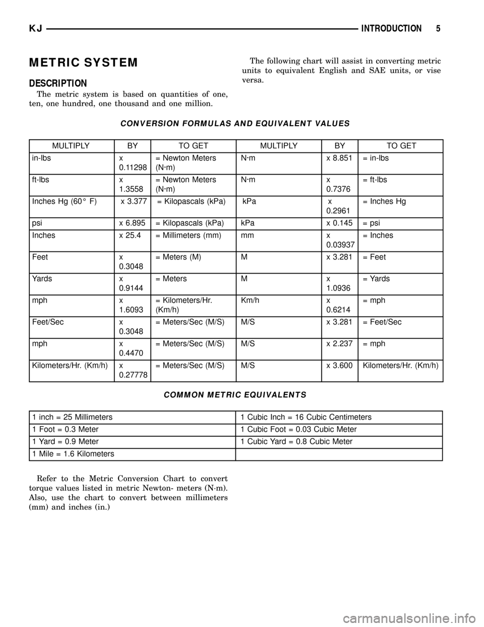
The metric system is based on quantities of one,
ten, one hundred, one thousand and one million.The following chart will assist in converting metric
units to equivalent English and SAE units, or vise
versa.
CONVERSION FORMULAS AND EQUIVALENT VALUES
MULTIPLY BY TO GET MULTIPLY BY TO GET
in-lbs x
0.11298= Newton Meters
(N´m)N´m x 8.851 = in-lbs
ft-lbs x
1.3558= Newton Meters
(N´m)N´m x
0.7376= ft-lbs
Inches Hg (60É F) x 3.377 = Kilopascals (kPa) kPa x
0.2961= Inches Hg
psi x 6.895 = Kilopascals (kPa) kPa x 0.145 = psi
Inches x 25.4 = Millimeters (mm) mm x
0.03937= Inches
Feet x
0.3048= Meters (M) M x 3.281 = Feet
Yards x
0.9144= Meters M x
1.0936= Yards
mph x
1.6093= Kilometers/Hr.
(Km/h)Km/h x
0.6214= mph
Feet/Sec x
0.3048= Meters/Sec (M/S) M/S x 3.281 = Feet/Sec
mph x
0.4470= Meters/Sec (M/S) M/S x 2.237 = mph
Kilometers/Hr. (Km/h) x
0.27778= Meters/Sec (M/S) M/S x 3.600 Kilometers/Hr. (Km/h)
COMMON METRIC EQUIVALENTS
1 inch = 25 Millimeters 1 Cubic Inch = 16 Cubic Centimeters
1 Foot = 0.3 Meter 1 Cubic Foot = 0.03 Cubic Meter
1 Yard = 0.9 Meter 1 Cubic Yard = 0.8 Cubic Meter
1 Mile = 1.6 Kilometers
Refer to the Metric Conversion Chart to convert
torque values listed in metric Newton- meters (N´m).
Also, use the chart to convert between millimeters
(mm) and inches (in.)
KJINTRODUCTION 5
Page 10 of 1803
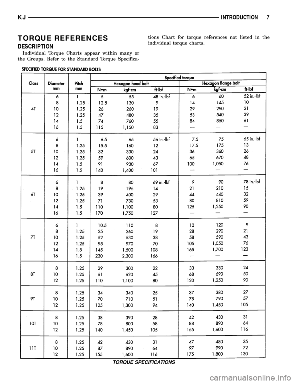
TORQUE REFERENCES
DESCRIPTION
Individual Torque Charts appear within many or
the Groups. Refer to the Standard Torque Specifica-tions Chart for torque references not listed in the
individual torque charts.
TORQUE SPECIFICATIONS
KJINTRODUCTION 7
Page 25 of 1803
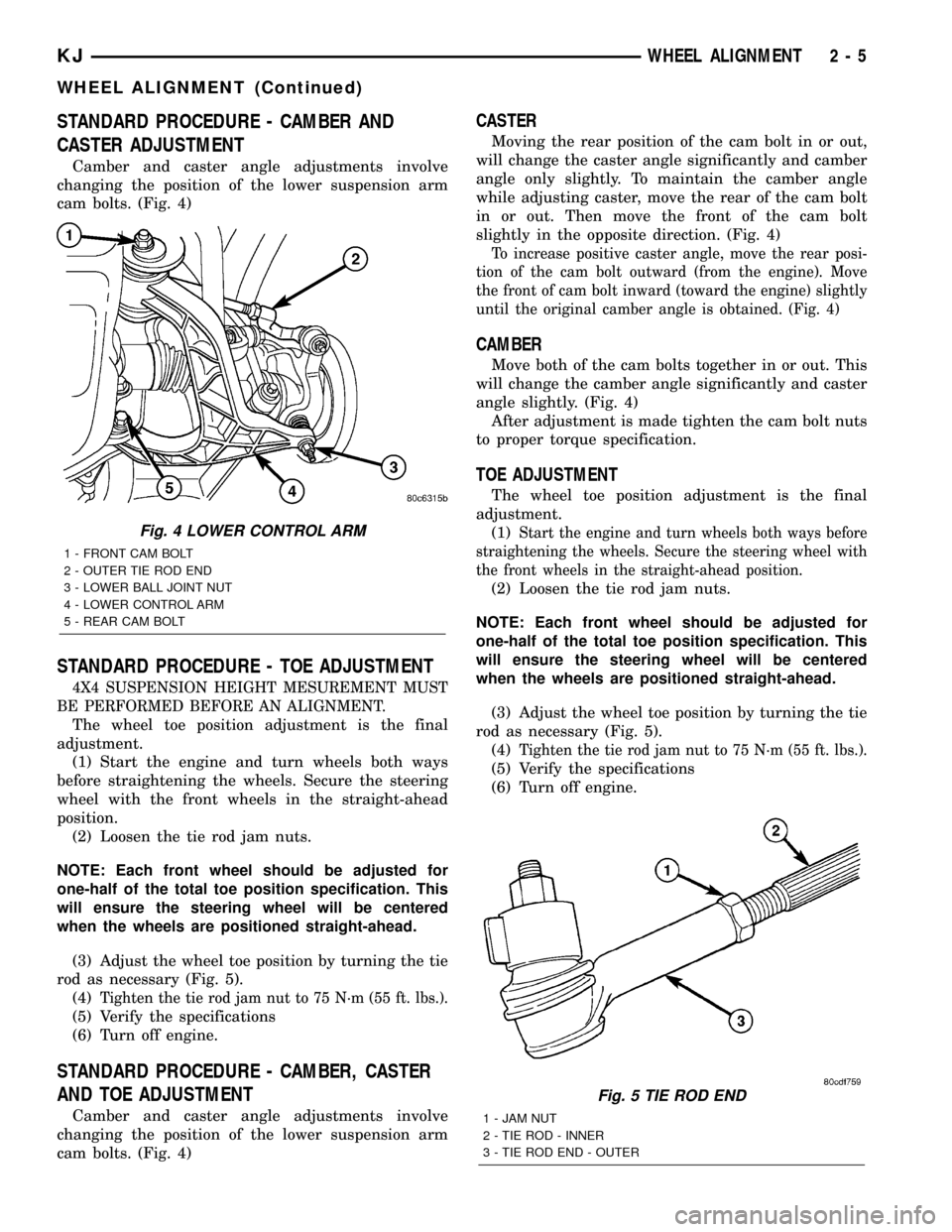
STANDARD PROCEDURE - CAMBER AND
CASTER ADJUSTMENT
Camber and caster angle adjustments involve
changing the position of the lower suspension arm
cam bolts. (Fig. 4)
STANDARD PROCEDURE - TOE ADJUSTMENT
4X4 SUSPENSION HEIGHT MESUREMENT MUST
BE PERFORMED BEFORE AN ALIGNMENT.
The wheel toe position adjustment is the final
adjustment.
(1) Start the engine and turn wheels both ways
before straightening the wheels. Secure the steering
wheel with the front wheels in the straight-ahead
position.
(2) Loosen the tie rod jam nuts.
NOTE: Each front wheel should be adjusted for
one-half of the total toe position specification. This
will ensure the steering wheel will be centered
when the wheels are positioned straight-ahead.
(3) Adjust the wheel toe position by turning the tie
rod as necessary (Fig. 5).
(4)
Tighten the tie rod jam nut to 75 N´m (55 ft. lbs.).
(5) Verify the specifications
(6) Turn off engine.
STANDARD PROCEDURE - CAMBER, CASTER
AND TOE ADJUSTMENT
Camber and caster angle adjustments involve
changing the position of the lower suspension arm
cam bolts. (Fig. 4)
CASTER
Moving the rear position of the cam bolt in or out,
will change the caster angle significantly and camber
angle only slightly. To maintain the camber angle
while adjusting caster, move the rear of the cam bolt
in or out. Then move the front of the cam bolt
slightly in the opposite direction. (Fig. 4)
To increase positive caster angle, move the rear posi-
tion of the cam bolt outward (from the engine). Move
the front of cam bolt inward (toward the engine) slightly
until the original camber angle is obtained. (Fig. 4)
CAMBER
Move both of the cam bolts together in or out. This
will change the camber angle significantly and caster
angle slightly. (Fig. 4)
After adjustment is made tighten the cam bolt nuts
to proper torque specification.
TOE ADJUSTMENT
The wheel toe position adjustment is the final
adjustment.
(1)
Start the engine and turn wheels both ways before
straightening the wheels. Secure the steering wheel with
the front wheels in the straight-ahead position.
(2) Loosen the tie rod jam nuts.
NOTE: Each front wheel should be adjusted for
one-half of the total toe position specification. This
will ensure the steering wheel will be centered
when the wheels are positioned straight-ahead.
(3) Adjust the wheel toe position by turning the tie
rod as necessary (Fig. 5).
(4)
Tighten the tie rod jam nut to 75 N´m (55 ft. lbs.).
(5) Verify the specifications
(6) Turn off engine.
Fig. 5 TIE ROD END
1 - JAM NUT
2 - TIE ROD - INNER
3 - TIE ROD END - OUTER
Fig. 4 LOWER CONTROL ARM
1 - FRONT CAM BOLT
2 - OUTER TIE ROD END
3 - LOWER BALL JOINT NUT
4 - LOWER CONTROL ARM
5 - REAR CAM BOLT
KJWHEEL ALIGNMENT 2 - 5
WHEEL ALIGNMENT (Continued)
Page 27 of 1803
FRONT
TABLE OF CONTENTS
page page
FRONT
DESCRIPTION..........................7
WARNING.............................7
SPECIFICATIONS
TORQUE CHART......................8
SPECIAL TOOLS
FRONT SUSPENSION...................8
BUSHINGS
REMOVAL - STABILIZER BAR BUSHINGS.....9
INSTALLATION - STABILIZER BAR BUSHINGS . . 9
HUB / BEARING
REMOVAL.............................9
INSTALLATION..........................9
KNUCKLE
REMOVAL.............................9
INSTALLATION..........................9
LOWER BALL JOINT
DIAGNOSIS AND TESTING - LOWER BALL
JOINT..............................10
LOWER CONTROL ARM
REMOVAL.............................10
INSTALLATION.........................10
SHOCK
REMOVAL
REMOVAL - LEFT SIDE.................11REMOVAL - RIGHT SIDE................11
INSTALLATION
INSTALLATION - LEFT SIDE.............12
INSTALLATION - RIGHT SIDE............12
SPRING
REMOVAL.............................13
INSTALLATION.........................13
CLEVIS BRACKET
REMOVAL.............................13
INSTALLATION.........................13
STABILIZER BAR
REMOVAL.............................14
INSTALLATION.........................14
STABILIZER LINK
REMOVAL.............................14
INSTALLATION.........................14
UPPER CONTROL ARM
REMOVAL
REMOVAL - RIGHT SIDE................14
REMOVAL - LEFT SIDE.................15
INSTALLATION
INSTALLATION - RIGHT SIDE............15
INSTALLATION - LEFT SIDE.............15
FRONT
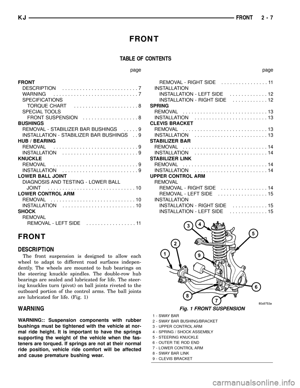
DESCRIPTION
The front suspension is designed to allow each
wheel to adapt to different road surfaces indepen-
dently. The wheels are mounted to hub bearings on
the steering knuckle spindles. The double-row hub
bearings are sealed and lubricated for life. The steer-
ing knuckles turn (pivot) on ball joints riveted to the
outboard portion of the control arms. The ball joints
are lubricated for life. (Fig. 1)
WARNING
WARNING:: Suspension components with rubber
bushings must be tightened with the vehicle at nor-
mal ride height. It is important to have the springs
supporting the weight of the vehicle when the fas-
teners are torqued. If springs are not at their normal
ride position, vehicle ride comfort will be affected
and cause premature bushing wear.
Fig. 1 FRONT SUSPENSION
1-SWAYBAR
2 - SWAY BAR BUSHING/BRACKET
3 - UPPER CONTROL ARM
4 - SPRING / SHOCK ASSEMBLY
5 - STEERING KNUCKLE
6 - OUTER TIE ROD END
7 - LOWER CONTROL ARM
8 - SWAY BAR LINK
9 - CLEVIS BRACKET
KJFRONT 2 - 7
Page 28 of 1803
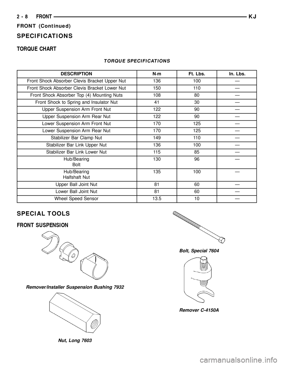
SPECIFICATIONS
TORQUE CHART
TORQUE SPECIFICATIONS
DESCRIPTION N´m Ft. Lbs. In. Lbs.
Front Shock Absorber Clevis Bracket Upper Nut 136 100 Ð
Front Shock Absorber Clevis Bracket Lower Nut 150 110 Ð
Front Shock Absorber Top (4) Mounting Nuts 108 80 Ð
Front Shock to Spring and Insulator Nut 41 30 Ð
Upper Suspension Arm Front Nut 122 90 Ð
Upper Suspension Arm Rear Nut 122 90 Ð
Lower Suspension Arm Front Nut 170 125 Ð
Lower Suspension Arm Rear Nut 170 125 Ð
Stabilizer Bar Clamp Nut 149 110 Ð
Stabilizer Bar Link Upper Nut 136 100 Ð
Stabilizer Bar Link Lower Nut 115 85 Ð
Hub/Bearing
Bolt130 96 Ð
Hub/Bearing
Halfshaft Nut135 100 Ð
Upper Ball Joint Nut 81 60 Ð
Lower Ball Joint Nut 81 60 Ð
Wheel Speed Sensor 13.5 10 Ð
SPECIAL TOOLS
FRONT SUSPENSION
Remover/Installer Suspension Bushing 7932
Nut, Long 7603
Bolt, Special 7604
Remover C-4150A
2 - 8 FRONTKJ
FRONT (Continued)
Page 36 of 1803
REAR
TABLE OF CONTENTS
page page
REAR
DESCRIPTION.........................16
WARNING.............................16
DIAGNOSIS AND TESTING - REAR
SUSPENSION........................17
SPECIFICATIONS
TORQUE CHART......................17
SHOCK
REMOVAL.............................18
INSTALLATION.........................18
SPRING
REMOVAL.............................18
INSTALLATION.........................18
JOUNCE BUMPER
REMOVAL.............................19
INSTALLATION.........................19
STABILIZER BAR
REMOVAL.............................19INSTALLATION.........................19
UPPER BALL JOINT
REMOVAL.............................20
INSTALLATION.........................20
UPPER CONTROL ARM
DESCRIPTION - UPPER SUSPENSION ARM,
BUSHINGS, AND BALL JOINT............20
OPERATION - UPPER SUSPENSION ARM,
BUSHINGS, AND BALL JOINT............20
REMOVAL.............................20
INSTALLATION.........................21
LOWER CONTROL ARM
DESCRIPTION.........................21
OPERATION...........................21
REMOVAL.............................21
INSTALLATION.........................21
REAR
DESCRIPTION
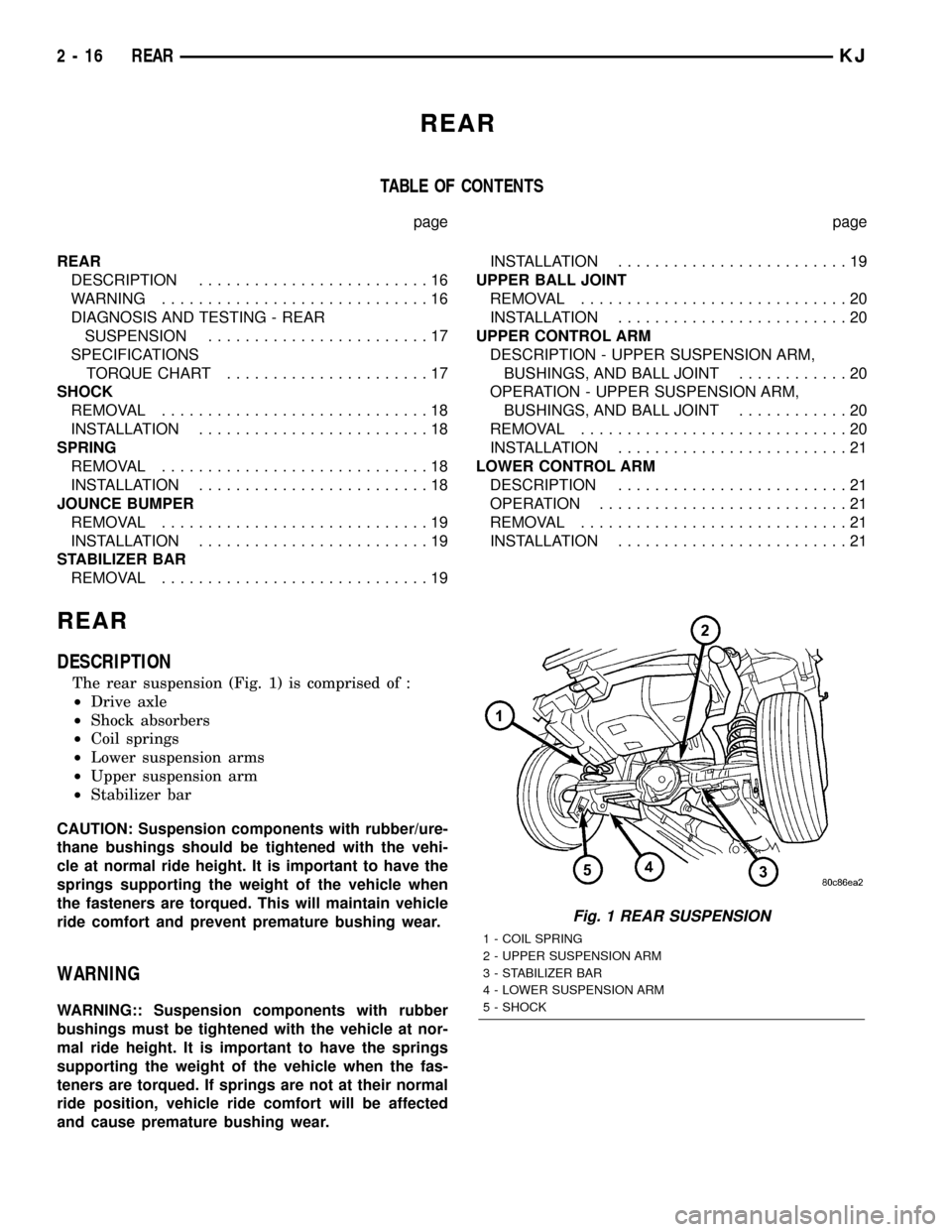
The rear suspension (Fig. 1) is comprised of :
²Drive axle
²Shock absorbers
²Coil springs
²Lower suspension arms
²Upper suspension arm
²Stabilizer bar
CAUTION: Suspension components with rubber/ure-
thane bushings should be tightened with the vehi-
cle at normal ride height. It is important to have the
springs supporting the weight of the vehicle when
the fasteners are torqued. This will maintain vehicle
ride comfort and prevent premature bushing wear.
WARNING
WARNING:: Suspension components with rubber
bushings must be tightened with the vehicle at nor-
mal ride height. It is important to have the springs
supporting the weight of the vehicle when the fas-
teners are torqued. If springs are not at their normal
ride position, vehicle ride comfort will be affected
and cause premature bushing wear.
Fig. 1 REAR SUSPENSION
1 - COIL SPRING
2 - UPPER SUSPENSION ARM
3 - STABILIZER BAR
4 - LOWER SUSPENSION ARM
5 - SHOCK
2 - 16 REARKJ
Page 37 of 1803
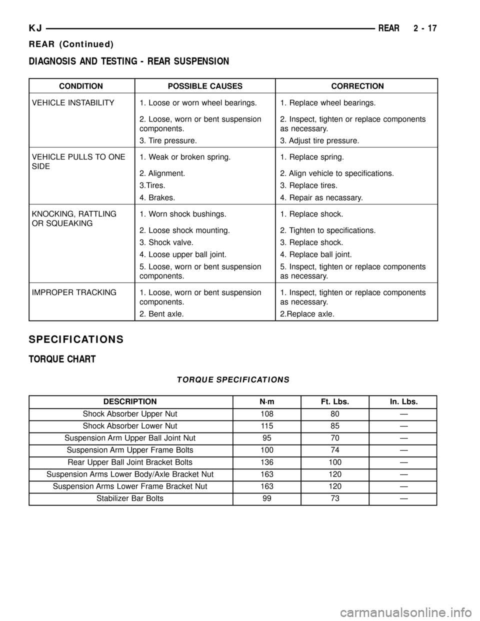
DIAGNOSIS AND TESTING - REAR SUSPENSION
CONDITION POSSIBLE CAUSES CORRECTION
VEHICLE INSTABILITY 1. Loose or worn wheel bearings. 1. Replace wheel bearings.
2. Loose, worn or bent suspension
components.2. Inspect, tighten or replace components
as necessary.
3. Tire pressure. 3. Adjust tire pressure.
VEHICLE PULLS TO ONE
SIDE1. Weak or broken spring. 1. Replace spring.
2. Alignment. 2. Align vehicle to specifications.
3.Tires. 3. Replace tires.
4. Brakes. 4. Repair as necassary.
KNOCKING, RATTLING
OR SQUEAKING1. Worn shock bushings. 1. Replace shock.
2. Loose shock mounting. 2. Tighten to specifications.
3. Shock valve. 3. Replace shock.
4. Loose upper ball joint. 4. Replace ball joint.
5. Loose, worn or bent suspension
components.5. Inspect, tighten or replace components
as necessary.
IMPROPER TRACKING 1. Loose, worn or bent suspension
components.1. Inspect, tighten or replace components
as necessary.
2. Bent axle. 2.Replace axle.
SPECIFICATIONS
TORQUE CHART
TORQUE SPECIFICATIONS
DESCRIPTION N´m Ft. Lbs. In. Lbs.
Shock Absorber Upper Nut 108 80 Ð
Shock Absorber Lower Nut 115 85 Ð
Suspension Arm Upper Ball Joint Nut 95 70 Ð
Suspension Arm Upper Frame Bolts 100 74 Ð
Rear Upper Ball Joint Bracket Bolts 136 100 Ð
Suspension Arms Lower Body/Axle Bracket Nut 163 120 Ð
Suspension Arms Lower Frame Bracket Nut 163 120 Ð
Stabilizer Bar Bolts 99 73 Ð
KJREAR 2 - 17
REAR (Continued)