hub bearing JEEP LIBERTY 2002 KJ / 1.G Workshop Manual
[x] Cancel search | Manufacturer: JEEP, Model Year: 2002, Model line: LIBERTY, Model: JEEP LIBERTY 2002 KJ / 1.GPages: 1803, PDF Size: 62.3 MB
Page 27 of 1803
FRONT
TABLE OF CONTENTS
page page
FRONT
DESCRIPTION..........................7
WARNING.............................7
SPECIFICATIONS
TORQUE CHART......................8
SPECIAL TOOLS
FRONT SUSPENSION...................8
BUSHINGS
REMOVAL - STABILIZER BAR BUSHINGS.....9
INSTALLATION - STABILIZER BAR BUSHINGS . . 9
HUB / BEARING
REMOVAL.............................9
INSTALLATION..........................9
KNUCKLE
REMOVAL.............................9
INSTALLATION..........................9
LOWER BALL JOINT
DIAGNOSIS AND TESTING - LOWER BALL
JOINT..............................10
LOWER CONTROL ARM
REMOVAL.............................10
INSTALLATION.........................10
SHOCK
REMOVAL
REMOVAL - LEFT SIDE.................11REMOVAL - RIGHT SIDE................11
INSTALLATION
INSTALLATION - LEFT SIDE.............12
INSTALLATION - RIGHT SIDE............12
SPRING
REMOVAL.............................13
INSTALLATION.........................13
CLEVIS BRACKET
REMOVAL.............................13
INSTALLATION.........................13
STABILIZER BAR
REMOVAL.............................14
INSTALLATION.........................14
STABILIZER LINK
REMOVAL.............................14
INSTALLATION.........................14
UPPER CONTROL ARM
REMOVAL
REMOVAL - RIGHT SIDE................14
REMOVAL - LEFT SIDE.................15
INSTALLATION
INSTALLATION - RIGHT SIDE............15
INSTALLATION - LEFT SIDE.............15
FRONT
DESCRIPTION
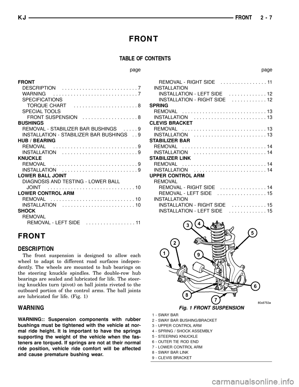
The front suspension is designed to allow each
wheel to adapt to different road surfaces indepen-
dently. The wheels are mounted to hub bearings on
the steering knuckle spindles. The double-row hub
bearings are sealed and lubricated for life. The steer-
ing knuckles turn (pivot) on ball joints riveted to the
outboard portion of the control arms. The ball joints
are lubricated for life. (Fig. 1)
WARNING
WARNING:: Suspension components with rubber
bushings must be tightened with the vehicle at nor-
mal ride height. It is important to have the springs
supporting the weight of the vehicle when the fas-
teners are torqued. If springs are not at their normal
ride position, vehicle ride comfort will be affected
and cause premature bushing wear.
Fig. 1 FRONT SUSPENSION
1-SWAYBAR
2 - SWAY BAR BUSHING/BRACKET
3 - UPPER CONTROL ARM
4 - SPRING / SHOCK ASSEMBLY
5 - STEERING KNUCKLE
6 - OUTER TIE ROD END
7 - LOWER CONTROL ARM
8 - SWAY BAR LINK
9 - CLEVIS BRACKET
KJFRONT 2 - 7
Page 28 of 1803
SPECIFICATIONS
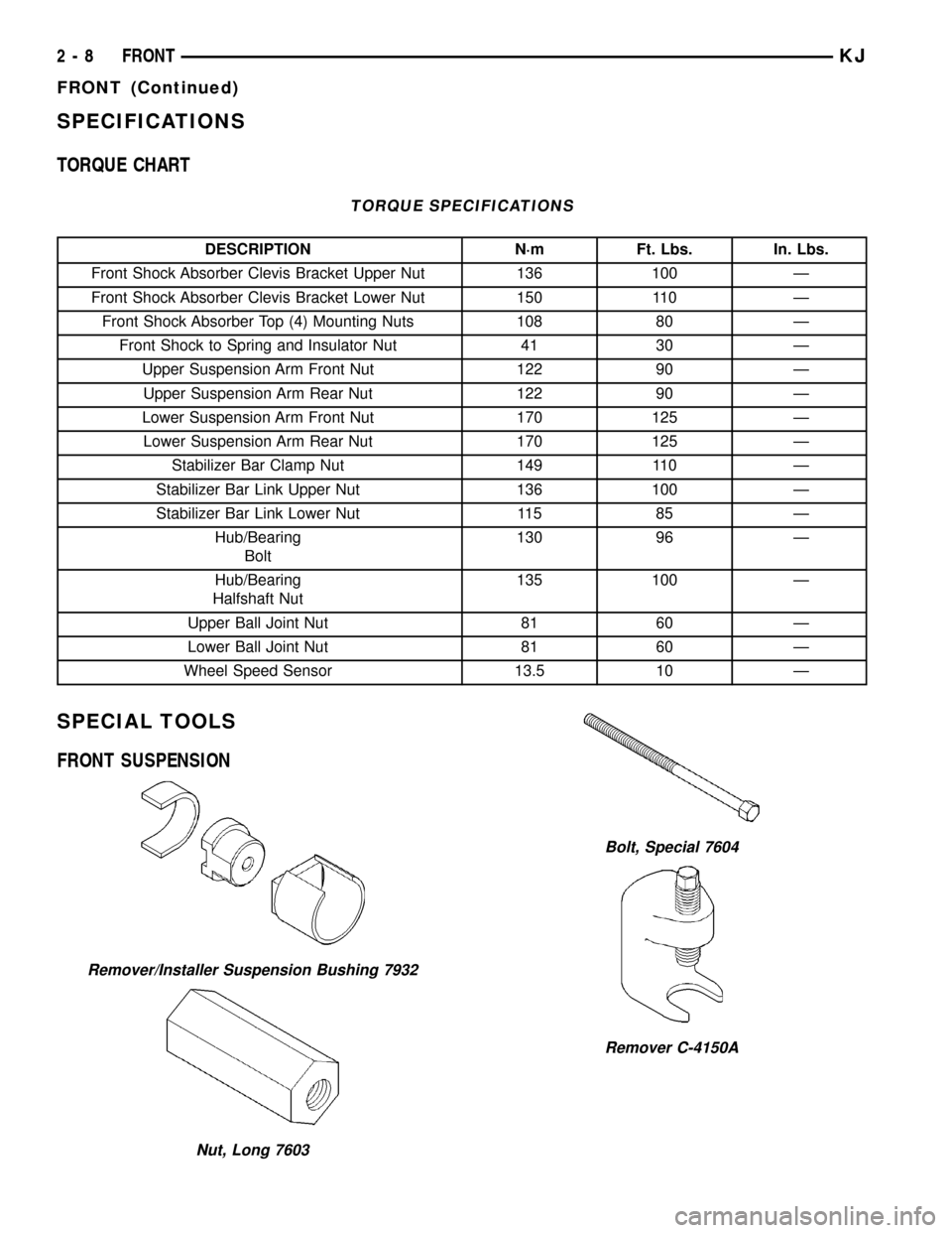
TORQUE CHART
TORQUE SPECIFICATIONS
DESCRIPTION N´m Ft. Lbs. In. Lbs.
Front Shock Absorber Clevis Bracket Upper Nut 136 100 Ð
Front Shock Absorber Clevis Bracket Lower Nut 150 110 Ð
Front Shock Absorber Top (4) Mounting Nuts 108 80 Ð
Front Shock to Spring and Insulator Nut 41 30 Ð
Upper Suspension Arm Front Nut 122 90 Ð
Upper Suspension Arm Rear Nut 122 90 Ð
Lower Suspension Arm Front Nut 170 125 Ð
Lower Suspension Arm Rear Nut 170 125 Ð
Stabilizer Bar Clamp Nut 149 110 Ð
Stabilizer Bar Link Upper Nut 136 100 Ð
Stabilizer Bar Link Lower Nut 115 85 Ð
Hub/Bearing
Bolt130 96 Ð
Hub/Bearing
Halfshaft Nut135 100 Ð
Upper Ball Joint Nut 81 60 Ð
Lower Ball Joint Nut 81 60 Ð
Wheel Speed Sensor 13.5 10 Ð
SPECIAL TOOLS
FRONT SUSPENSION
Remover/Installer Suspension Bushing 7932
Nut, Long 7603
Bolt, Special 7604
Remover C-4150A
2 - 8 FRONTKJ
FRONT (Continued)
Page 29 of 1803
BUSHINGS
REMOVAL - STABILIZER BAR BUSHINGS
(1) Raise vehicle on hoist.
(2) Remove the stabilizer bushing clamps.
(3) Remove the stabilizer bushings from the stabi-
lizer bar.
INSTALLATION - STABILIZER BAR BUSHINGS
(1) Install the stabilizer bushings to the stabilizer
bar.
(2) Install the stabilizer bushing clamps. Tighten
the nuts to 149 N´m (110 ft.lbs.).
(3) Lower the vehicle.
HUB / BEARING
REMOVAL
(1) Raise and support the vehicle.
(2) Remove the tire and wheel assembly.
(3) Remove the caliper adapter (Refer to 5 -
BRAKES/HYDRAULIC/MECHANICAL/DISC
BRAKE CALIPERS - REMOVAL).
CAUTION: Never allow the disc brake caliper to
hang from the brake hose. Damage to the brake
hose will result. Provide a suitable support to hang
the caliper securely.
(4) Remove the disc brake rotor (Refer to 5 -
BRAKES/HYDRAULIC/MECHANICAL/ROTORS -
REMOVAL).
(5) Remove the wheel speed sensor (Refer to 5 -
BRAKES/ELECTRICAL/FRONT WHEEL SPEED
SENSOR - REMOVAL).
(6) Remove the bracket securing the wheel speed
sensor wire.
(7) Remove the axle shaft nut. (if equipped with
four wheel drive)
(8) Remove the three mounting bolts for the hub/
bearing assembly.
(9) Remove the hub/bearing.
INSTALLATION
(1) Install the hub/bearing assembly to the vehicle.
(2) Install the three mounting bolts for the hub/
bearing. Tighten the bolt to 130 N´m (96 ft.lbs.).
(3) Install the axle shaft nut. Tighten the nut to
135 N´m (100 ft.lbs.). (if equipped with four wheel
drive)
(4) Install the bracket to the wheel speed sensor
wire.
(5) Install the wheel speed sensor to the hub.
Tighten the bolt to 13.5 N´m (10 ft.lbs.) (Refer to 5 -BRAKES/ELECTRICAL/FRONT WHEEL SPEED
SENSOR - INSTALLATION).
(6) Install the disc brake rotor (Refer to 5 -
BRAKES/HYDRAULIC/MECHANICAL/ROTORS -
INSTALLATION).
(7) Install the disc brake caliper adapter. Tighten
the nut to 135 N´m (100 ft.lbs.) (Refer to 5 -
BRAKES/HYDRAULIC/MECHANICAL/ROTORS -
INSTALLATION).
(8) Install the tire and wheel assembly. (Refer to
22 - TIRES/WHEELS/WHEELS - STANDARD PRO-
CEDURE).
KNUCKLE
REMOVAL
(1) Raise and support the vehicle.
(2) Remove the tire and wheel assembly.
(3) Remove the caliper adapter. (Refer to 5 -
BRAKES/HYDRAULIC/MECHANICAL/DISC
BRAKE CALIPER ADAPTER - REMOVAL).
CAUTION: Never allow the disc brake caliper to
hang from the brake hose. Damage to the brake
hose will result. Provide a suitable support to hang
the caliper securely.
(4) Remove the disc brake rotor. (Refer to 5 -
BRAKES/HYDRAULIC/MECHANICAL/ROTORS -
REMOVAL).
(5) Remove the wheel speed sensor. (Refer to 5 -
BRAKES/ELECTRICAL/FRONT WHEEL SPEED
SENSOR - REMOVAL).
(6) Remove the axle shaft nut. (if equipped with
four wheel drive)
(7) Remove the hub/bearing. (Refer to 2 - SUS-
PENSION/FRONT/HUB / BEARING - REMOVAL).
(8) Remove the outer tie rod end. (Refer to 19 -
STEERING/LINKAGE/TIE ROD END - REMOVAL).
(9) Remove the lower ball joint nut.
(10) Seperate the lower ball joint from the suspen-
sion arm using tool C±4150A.
(11) Remove the upper ball joint nut.
(12) Seperate the upper ball joint from the knuckle
using tool C±4150A.
(13) Remove the knuckle from the vehicle.
INSTALLATION
(1) Install the knuckle to the vehicle.
(2) Install the upper ball joint nut. Tighten the nut
to 81 N´m (60 ft.lbs.).
(3) Install the lower ball joint nut. Tighten the nut
to 81 N´m (60 ft.lbs.).
(4) Install the outer tie rod end. (Refer to 19 -
STEERING/LINKAGE/TIE ROD END - INSTALLA-
TION).
KJFRONT 2 - 9
Page 30 of 1803
(5) Install the hub/bearing. (Refer to 2 - SUSPEN-
SION/FRONT/HUB / BEARING - INSTALLATION).
(6) Install the axle shaft nut. Tighten the nut to
135 N´m (96 ft.lbs.).(if equipped with four wheel
drive).
(7) Install the wheel speed sensor. (Refer to 5 -
BRAKES/ELECTRICAL/FRONT WHEEL SPEED
SENSOR - INSTALLATION).
(8) Install the disc brake rotor. (Refer to 5 -
BRAKES/HYDRAULIC/MECHANICAL/ROTORS -
INSTALLATION).
(9) Install the caliper adapter. (Refer to 5 -
BRAKES/HYDRAULIC/MECHANICAL/DISC
BRAKE CALIPER ADAPTER - INSTALLATION).
(10) Install the tire and wheel assembly. (Refer to
22 - TIRES/WHEELS/WHEELS - STANDARD PRO-
CEDURE).
(11) Perform the set toe procedure (Refer to 2 -
SUSPENSION/WHEEL ALIGNMENT - STANDARD
PROCEDURE).
LOWER BALL JOINT
DIAGNOSIS AND TESTING - LOWER BALL
JOINT
(1) Raise the vehicle on a drive-on hoist.
NOTE: If a drive-on hoist is not available, use
wooden blocks with jack stands to support the
lower control arm in the ball joint area. Place the
jack stands appropriately and lower the hoist plac-
ing weight on the lower control arm. The lower con-
trol arms should now be supporting the vehicle
weight.
(2) With the use of jack stands, lift the front end
off the hoist and position wooden blocks underneath
both lower control arms supporting the vehicles
weight.
(3) Remove the tire and wheel assembly.
(4) Attach a dial indicator to the base of the lower
control arm and align the dial indicator's contact
point with the direction of the stud axis, touch the
machined flat on the knuckle and zero the dial indi-
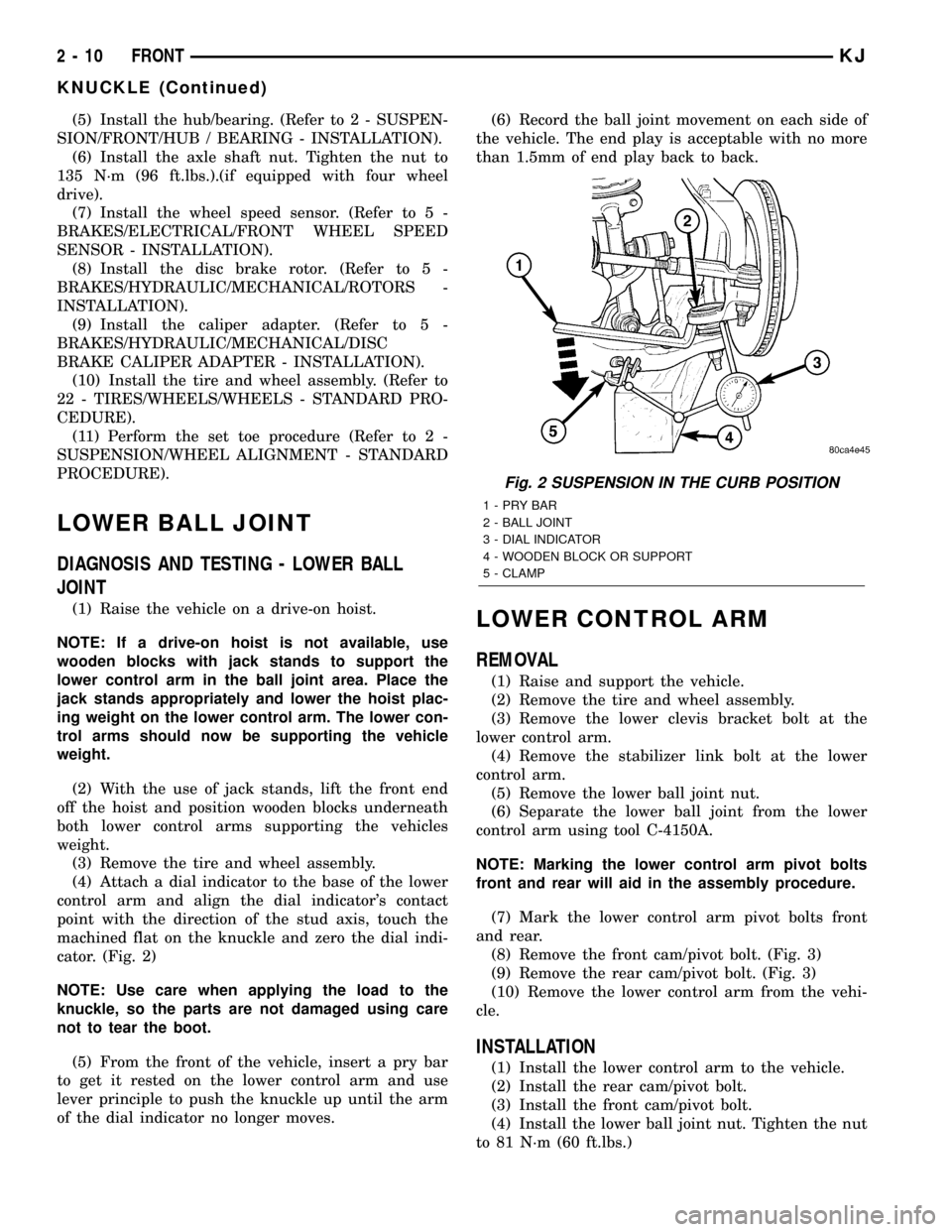
cator. (Fig. 2)
NOTE: Use care when applying the load to the
knuckle, so the parts are not damaged using care
not to tear the boot.
(5) From the front of the vehicle, insert a pry bar
to get it rested on the lower control arm and use
lever principle to push the knuckle up until the arm
of the dial indicator no longer moves.(6) Record the ball joint movement on each side of
the vehicle. The end play is acceptable with no more
than 1.5mm of end play back to back.LOWER CONTROL ARM
REMOVAL
(1) Raise and support the vehicle.
(2) Remove the tire and wheel assembly.
(3) Remove the lower clevis bracket bolt at the
lower control arm.
(4) Remove the stabilizer link bolt at the lower
control arm.
(5) Remove the lower ball joint nut.
(6) Separate the lower ball joint from the lower
control arm using tool C-4150A.
NOTE: Marking the lower control arm pivot bolts
front and rear will aid in the assembly procedure.
(7) Mark the lower control arm pivot bolts front
and rear.
(8) Remove the front cam/pivot bolt. (Fig. 3)
(9) Remove the rear cam/pivot bolt. (Fig. 3)
(10) Remove the lower control arm from the vehi-
cle.
INSTALLATION
(1) Install the lower control arm to the vehicle.
(2) Install the rear cam/pivot bolt.
(3) Install the front cam/pivot bolt.
(4) Install the lower ball joint nut. Tighten the nut
to 81 N´m (60 ft.lbs.)
Fig. 2 SUSPENSION IN THE CURB POSITION
1-PRYBAR
2 - BALL JOINT
3 - DIAL INDICATOR
4 - WOODEN BLOCK OR SUPPORT
5 - CLAMP
2 - 10 FRONTKJ
KNUCKLE (Continued)
Page 60 of 1803
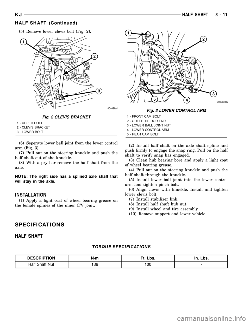
(5) Remove lower clevis bolt (Fig. 2).
(6) Seperate lower ball joint from the lower control
arm (Fig. 3).
(7) Pull out on the steering knuckle and push the
half shaft out of the knuckle.
(8) With a pry bar remove the half shaft from the
axle.
NOTE: The right side has a splined axle shaft that
will stay in the axle.
INSTALLATION
(1) Apply a light coat of wheel bearing grease on
the female splines of the inner C/V joint.(2) Install half shaft on the axle shaft spline and
push firmly to engage the snap ring. Pull on the half
shaft to verify snap has engaged.
(3) Clean hub bearing bore and apply a light coat
of wheel bearing grease.
(4) Pull out on the steering knuckle and push the
half shaft through the knuckle.
(5) Install lower ball joint into the lower control
arm and tighten pinch bolt.
(6) Align clevis with knuckle. Install and tighten
lower clevis bolt.
(7) Install stabilizer link.
(8) Install half shaft hub nut.
(9) Install wheel and tire assembly.
(10) Remove support and lower vehicle.
SPECIFICATIONS
HALF SHAFT
TORQUE SPECIFICATIONS
DESCRIPTION N´m Ft. Lbs. In. Lbs.
Half Shaft Nut 136 100 -
Fig. 3 LOWER CONTROL ARM
1 - FRONT CAM BOLT
2 - OUTER TIE ROD END
3 - LOWER BALL JOINT NUT
4 - LOWER CONTROL ARM
5 - REAR CAM BOLTFig. 2 CLEVIS BRACKET
1 - UPPER BOLT
2 - CLEVIS BRACKET
3 - LOWER BOLT
KJHALF SHAFT 3 - 11
HALF SHAFT (Continued)
Page 61 of 1803
SPECIAL TOOLS
CV JOINT/BOOT-OUTER
REMOVAL
(1) Clamp shaft in a vise (with soft jaws) and sup-
port C/V joint.
(2) Remove clamps with a cut-off wheel or grinder
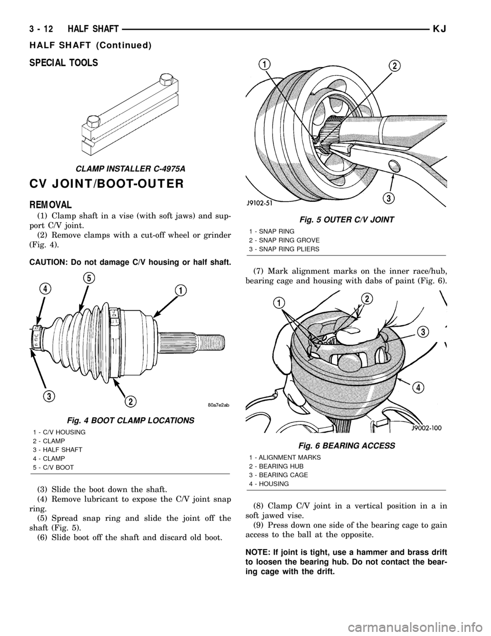
(Fig. 4).
CAUTION: Do not damage C/V housing or half shaft.
(3) Slide the boot down the shaft.
(4) Remove lubricant to expose the C/V joint snap
ring.
(5) Spread snap ring and slide the joint off the
shaft (Fig. 5).
(6) Slide boot off the shaft and discard old boot.(7) Mark alignment marks on the inner race/hub,
bearing cage and housing with dabs of paint (Fig. 6).
(8) Clamp C/V joint in a vertical position in a in
soft jawed vise.
(9) Press down one side of the bearing cage to gain
access to the ball at the opposite.
NOTE: If joint is tight, use a hammer and brass drift
to loosen the bearing hub. Do not contact the bear-
ing cage with the drift.
CLAMP INSTALLER C-4975A
Fig. 4 BOOT CLAMP LOCATIONS
1 - C/V HOUSING
2 - CLAMP
3 - HALF SHAFT
4 - CLAMP
5 - C/V BOOT
Fig. 5 OUTER C/V JOINT
1 - SNAP RING
2 - SNAP RING GROVE
3 - SNAP RING PLIERS
Fig. 6 BEARING ACCESS
1 - ALIGNMENT MARKS
2 - BEARING HUB
3 - BEARING CAGE
4 - HOUSING
3 - 12 HALF SHAFTKJ
HALF SHAFT (Continued)
Page 62 of 1803
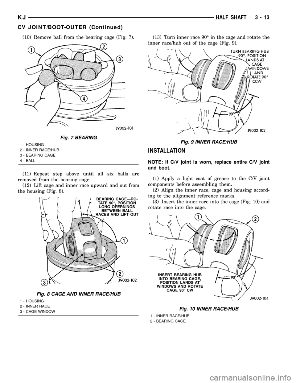
(10) Remove ball from the bearing cage (Fig. 7).
(11) Repeat step above until all six balls are
removed from the bearing cage.
(12) Lift cage and inner race upward and out from
the housing (Fig. 8).(13) Turn inner race 90É in the cage and rotate the
inner race/hub out of the cage (Fig. 9).
INSTALLATION
NOTE: If C/V joint is worn, replace entire C/V joint
and boot.
(1) Apply a light coat of grease to the C/V joint
components before assembling them.
(2) Align the inner race, cage and housing accord-
ing to the alignment reference marks.
(3) Insert the inner race into the cage (Fig. 10) and
rotate race into the cage.
Fig. 7 BEARING
1 - HOUSING
2 - INNER RACE/HUB
3 - BEARING CAGE
4 - BALL
Fig. 8 CAGE AND INNER RACE/HUB
1 - HOUSING
2 - INNER RACE
3 - CAGE WINDOW
Fig. 9 INNER RACE/HUB
Fig. 10 INNER RACE/HUB
1 - INNER RACE/HUB
2 - BEARING CAGE
KJHALF SHAFT 3 - 13
CV JOINT/BOOT-OUTER (Continued)
Page 63 of 1803
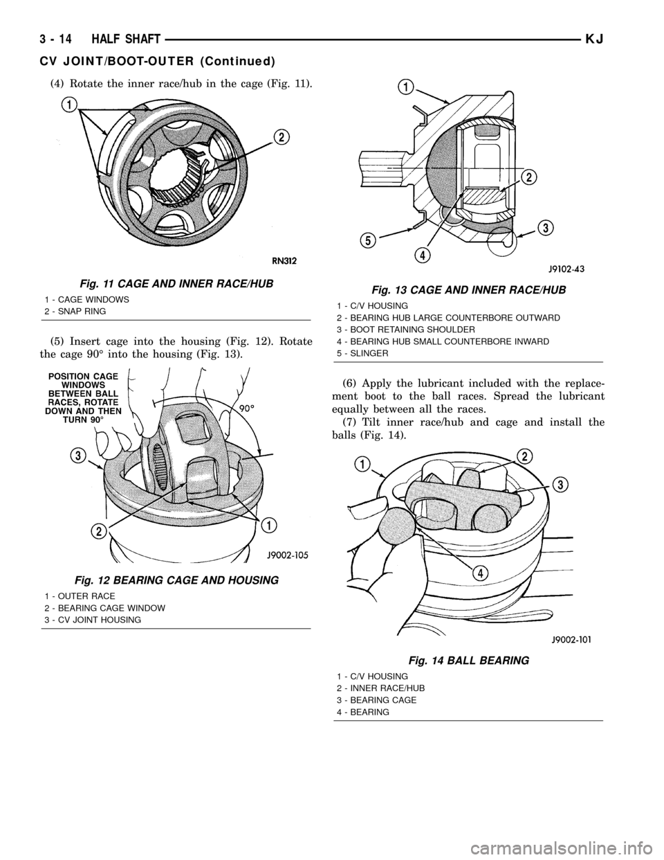
(4) Rotate the inner race/hub in the cage (Fig. 11).
(5) Insert cage into the housing (Fig. 12). Rotate
the cage 90É into the housing (Fig. 13).
(6) Apply the lubricant included with the replace-
ment boot to the ball races. Spread the lubricant
equally between all the races.
(7) Tilt inner race/hub and cage and install the
balls (Fig. 14).
Fig. 11 CAGE AND INNER RACE/HUB
1 - CAGE WINDOWS
2 - SNAP RING
Fig. 12 BEARING CAGE AND HOUSING
1 - OUTER RACE
2 - BEARING CAGE WINDOW
3 - CV JOINT HOUSING
Fig. 13 CAGE AND INNER RACE/HUB
1 - C/V HOUSING
2 - BEARING HUB LARGE COUNTERBORE OUTWARD
3 - BOOT RETAINING SHOULDER
4 - BEARING HUB SMALL COUNTERBORE INWARD
5 - SLINGER
Fig. 14 BALL BEARING
1 - C/V HOUSING
2 - INNER RACE/HUB
3 - BEARING CAGE
4 - BEARING
3 - 14 HALF SHAFTKJ
CV JOINT/BOOT-OUTER (Continued)
Page 64 of 1803
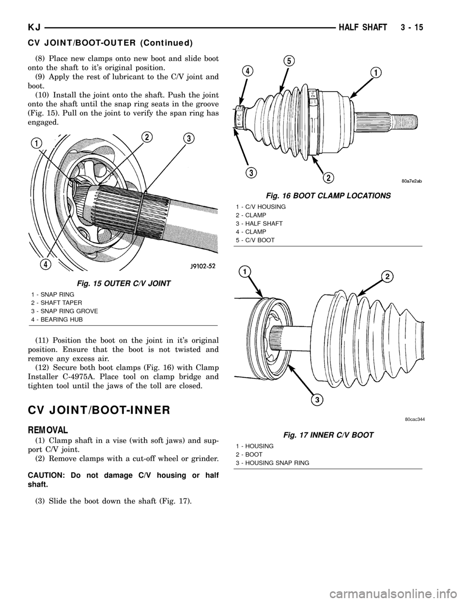
(8) Place new clamps onto new boot and slide boot
onto the shaft to it's original position.
(9) Apply the rest of lubricant to the C/V joint and
boot.
(10) Install the joint onto the shaft. Push the joint
onto the shaft until the snap ring seats in the groove
(Fig. 15). Pull on the joint to verify the span ring has
engaged.
(11) Position the boot on the joint in it's original
position. Ensure that the boot is not twisted and
remove any excess air.
(12) Secure both boot clamps (Fig. 16) with Clamp
Installer C-4975A. Place tool on clamp bridge and
tighten tool until the jaws of the toll are closed.
CV JOINT/BOOT-INNER
REMOVAL
(1) Clamp shaft in a vise (with soft jaws) and sup-
port C/V joint.
(2) Remove clamps with a cut-off wheel or grinder.
CAUTION: Do not damage C/V housing or half
shaft.
(3) Slide the boot down the shaft (Fig. 17).
Fig. 15 OUTER C/V JOINT
1 - SNAP RING
2 - SHAFT TAPER
3 - SNAP RING GROVE
4 - BEARING HUB
Fig. 16 BOOT CLAMP LOCATIONS
1 - C/V HOUSING
2 - CLAMP
3 - HALF SHAFT
4 - CLAMP
5 - C/V BOOT
Fig. 17 INNER C/V BOOT
1 - HOUSING
2 - BOOT
3 - HOUSING SNAP RING
KJHALF SHAFT 3 - 15
CV JOINT/BOOT-OUTER (Continued)
Page 68 of 1803
FRONT AXLE - 186FIA
TABLE OF CONTENTS
page page
FRONT AXLE - 186FIA
DESCRIPTION.........................19
OPERATION...........................19
DIAGNOSIS AND TESTING - AXLE..........20
REMOVAL.............................24
INSTALLATION.........................24
ADJUSTMENTS........................25
SPECIFICATIONS - FRONT AXLE...........33
SPECIAL TOOLS
FRONT AXLE........................34
AXLE SHAFTS
REMOVAL.............................37
INSTALLATION.........................37
AXLE SHAFT SEALS
REMOVAL.............................37
INSTALLATION.........................38
AXLE BEARINGS
REMOVAL.............................38INSTALLATION.........................38
PINION SEAL
REMOVAL.............................38
INSTALLATION.........................39
DIFFERENTIAL
REMOVAL.............................40
DISASSEMBLY.........................41
ASSEMBLY............................41
INSTALLATION.........................42
DIFFERENTIAL CASE BEARINGS
REMOVAL.............................43
INSTALLATION.........................44
PINION GEAR/RING GEAR
REMOVAL.............................44
INSTALLATION.........................46
FRONT AXLE - 186FIA
DESCRIPTION
The 186FIA (Model 30) axle consists of an alumu-
num center section with an axle tube extending from
one side. The tube is pressed into the differential
housing. The integral type housing, hypoid gear
design has the centerline of the pinion set below the
centerline of the ring gear.
The differential case is a one-piece design. The differ-
ential pinion mate shaft is retained with a roll-pin. Dif-
ferential bearing preload and ring gear backlash is
adjusted by the use of shims (select thickness). The
shims are located between the differential bearing cups
and the axle housing. Pinion bearing preload is set and
maintained by the use of a collapsible spacer.
The power is transferred from the axle through two
constant velocity (C/V) drive shafts to the wheel hubs.
The differential cover provides a means for inspec-
tion and service without removing the axle from the
vehicle. The cover has a vent tube used to relieve
internal pressure caused by vaporization and inter-
nal expansion.
OPERATION
The axle receives power from the transfer case through
the front propeller shaft. The front propeller shaft is con-
nected to the pinion gear which rotates the differential
through the gear mesh with the ring gear bolted to thedifferential case. The engine power is transmitted to the
axle shafts through the pinion mate and side gears. The
side gears are splined to the axle shafts.
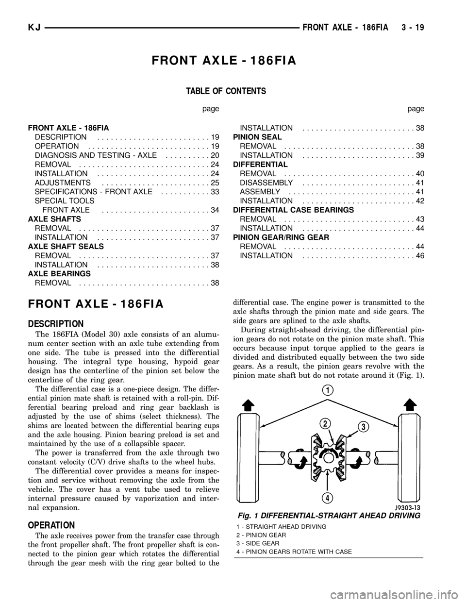
During straight-ahead driving, the differential pin-
ion gears do not rotate on the pinion mate shaft. This
occurs because input torque applied to the gears is
divided and distributed equally between the two side
gears. As a result, the pinion gears revolve with the
pinion mate shaft but do not rotate around it (Fig. 1).
Fig. 1 DIFFERENTIAL-STRAIGHT AHEAD DRIVING
1 - STRAIGHT AHEAD DRIVING
2 - PINION GEAR
3 - SIDE GEAR
4 - PINION GEARS ROTATE WITH CASE
KJFRONT AXLE - 186FIA 3 - 19