JEEP LIBERTY 2012 KK / 2.G Manual PDF
Manufacturer: JEEP, Model Year: 2012, Model line: LIBERTY, Model: JEEP LIBERTY 2012 KK / 2.GPages: 124, PDF Size: 2.92 MB
Page 71 of 124
Programming A Rolling Code
• For programming Garage Door Openers that were manufactured after1995. These Garage Door Openers can be identified by the “LEARN” or
“TRAIN” button located where the hanging antenna is attached to the
Garage Door Opener. It is NOT the button that is normally used to open
and close the door. The name and color of the button may vary by
manufacturer.
• Place the ignition switch into the ON/RUN position.
• Place the hand-held transmitter 1 to 3 in (3 to 8 cm) away from the HomeLink® button you wish to program while keeping the HomeLink®
indicator light in view.
• Simultaneously press and hold both the HomeLink® button you want to program and the hand-held transmitter button.
• Continue to hold both buttons and observe the indicator light. The Homelink® indicator will flash slowly and then rapidly after Homelink® has
received the frequency signal from the hand-held transmitter. Release
both buttons after the indicator light changes from slow to rapid.
• At the garage door opener motor (in the garage), locate the “LEARN” or “TRAINING” button. This can usually be found where the hanging
antenna wire is attached to the garage door opener motor. Firmly press
and release the “LEARN” or “TRAINING” button.
NOTE: You have 30 seconds in which to initiate the next step after the
LEARN button has been pressed.
• Return to the vehicle and press the programmed HomeLink® buttontwice (holding the button for two seconds each time). If the device is
plugged in and activates, programming is complete.
NOTE: If the device does not activate, press the button a third time (for two
seconds) to complete the training.
• To program the remaining two HomeLink® buttons, repeat each step foreach remaining button. DO NOT erase the channels.
ELECTRONICS
69
Page 72 of 124
Programming A Non-Rolling Code
• For programming Garage Door Openers manufactured before 1995.
• Turn the ignition switch to the ON/RUN position.
• Place the hand-held transmitter 1 to 3 in (3 to 8 cm) away from theHomeLink® button you wish to program while keeping the HomeLink®
indicator light in view.
• Simultaneously press and hold both the HomeLink® button you want to program and the hand-held transmitter button.
• Continue to hold both buttons and observe the indicator light. The Homelink® indicator will flash slowly and then rapidly after Homelink® has
received the frequency signal from the hand-held transmitter. Release
both buttons after the indicator light changes from slow to rapid.
• Press and hold the programmed HomeLink® button and observe the indicator light.
NOTE:
• If the indicator light stays on constantly, programming is complete and the garage door (or device) should activate when the HomeLink® button is
pressed.
• To program the two remaining HomeLink® buttons, repeat each step for each remaining button. DO NOT erase the channels.
Using HomeLink®
• To operate, press and release the programmed HomeLink® button.Activation will now occur for the programmed device (i.e., garage door
opener, gate operator, security system, entry door lock, home/office
lighting, etc.,). The hand-held transmitter of the device may also be used
at any time.
WARNING!
• Your motorized door or gate will open and close while you areprogramming the universal transceiver. Do not program the
transceiver if people or pets are in the path of the door or gate.
• Do not run your vehicle in a closed garage or confined area while programming the transceiver. Exhaust gas from your vehicle
contains Carbon Monoxide (CO) which is odorless and colorless.
Carbon Monoxide is poisonous when inhaled and can cause you and
others to be severely injured or killed.
ELECTRONICS
70
Page 73 of 124
POWER OUTLET
• The power outlet is located on the instrument panel below the climatecontrol and is powered when the ignition switch is in the ON/RUN
position.
• The outlet can operate a conventional cigar lighter unit or power accessories designed for use with a standard power outlet adapter.
NOTE:
• Do not exceed the maximum power of 160 Watts (13 Amps) at 12 Volts. If the 160 Watt (13 Amp) power rating is exceeded, the fuse protecting the
system will need to be replaced.
• Power outlets are designed for accessory plugs only. Do not insert any other object in the power outlet as this will damage the outlet and blow
the fuse. Improper use of the power outlet can cause damage not covered
by your new vehicle warranty.
ELECTRONICS
71
Page 74 of 124
FOUR-WHEEL DRIVE OPERATION
Command-Trac II® Transfer Case
• The Command-TracII® transfer case provides four positions:• Two-wheel drive (2WD) high range
• Four-wheel drive (4WD LOCK) high range
• Four-wheel drive (4WD LOW) low range
• NEUTRAL (N)
2WD To 4WD LOCK
• Move transfer case lever to the desired position.
• Shifts between 2WD and 4WD LOCK can be done with the vehicle stopped or in motion. With the vehicle in motion, the transfer case will
engage/disengage faster if you momentarily release the accelerator
pedal after moving the transfer case lever.
• If the vehicle is stopped, the key must be in the ON/RUN position.
• Shifts can not be completed if the key is in the ACC position.
4WD LOCK To 4WD LOW
• With the engine running, slow the vehicle speed to 2 to 3 mph (3 to 5 km/h) and shift the transmission into NEUTRAL.
• While still rolling, move the transfer case lever to the 4WD LOW position.
• After the indicator light is ON (not flashing) shift the transmission into gear.
• If the indicator light in the instrument cluster is flashing, the shift did not occur and the current transfer case position will be maintained.
• This transfer case is intended to be driven in the two-wheel drive position (2WD) for normal street and highway conditions such as dry,
hard-surfaced roads.
• When additional traction is required, select the transfer case 4WD LOCK position or 4WD LOW position. This position locks the front driveshaft
and rear driveshaft together and forces the front and rear wheels to
rotate at the same speed.
• When operating in 4WD LOW, the engine speed is approximately three times that of the 4WD LOCK position at a given road speed. Take care
not to over-speed the engine and do not exceed 25 mph (40 km/h).
• Use the transfer case NEUTRAL position for recreational towing only.
Selec-Trac II® Transfer Case
• The Selec-Trac II® active on-demand transfer case provides four positions:
• Two-wheel drive (2WD) high range
• Four-wheel drive Auto (4WD AUTO) high range
• NEUTRAL (N)
• Four-wheel drive (4WD LOW) low range
OFF-ROAD CAPABILITIES
72
Page 75 of 124
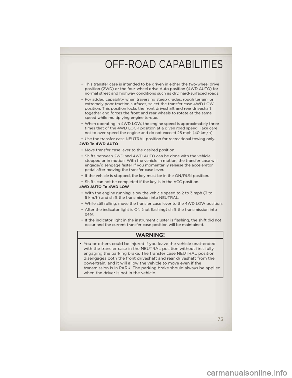
• This transfer case is intended to be driven in either the two-wheel driveposition (2WD) or the four-wheel drive Auto position (4WD AUTO) for
normal street and highway conditions such as dry, hard-surfaced roads.
• For added capability when traversing steep grades, rough terrain, or extremely poor traction surfaces, select the transfer case 4WD LOW
position. This position locks the front driveshaft and rear driveshaft
together and forces the front and rear wheels to rotate at the same
speed while multiplying engine torque.
• When operating in 4WD LOW, the engine speed is approximately three times that of the 4WD LOCK position at a given road speed. Take care
not to over-speed the engine and do not exceed 25 mph (40 km/h).
• Use the transfer case NEUTRAL position for recreational towing only.
2WD To 4WD AUTO
• Move transfer case lever to the desired position.
• Shifts between 2WD and 4WD AUTO can be done with the vehicle stopped or in motion. With the vehicle in motion, the transfer case will
engage/disengage faster if you momentarily release the accelerator
pedal after moving the transfer case lever.
• If the vehicle is stopped, the key must be in the ON/RUN position.
• Shifts can not be completed if the key is in the ACC position.
4WD AUTO To 4WD LOW
• With the engine running, slow the vehicle speed to 2 to 3 mph (3 to 5 km/h) and shift the transmission into NEUTRAL.
• While still rolling, move the transfer case lever to the 4WD LOW position.
• After the indicator light is ON (not flashing) shift the transmission into gear.
• If the indicator light in the instrument cluster is flashing, the shift did not occur and the current transfer case position will be maintained.
WARNING!
• You or others could be injured if you leave the vehicle unattendedwith the transfer case in the NEUTRAL position without first fully
engaging the parking brake. The transfer case NEUTRAL position
disengages both the front driveshaft and rear driveshaft from the
powertrain, and it will allow the vehicle to move even if the
transmission is in PARK. The parking brake should always be applied
when the driver is not in the vehicle.
OFF-ROAD CAPABILITIES
73
Page 76 of 124
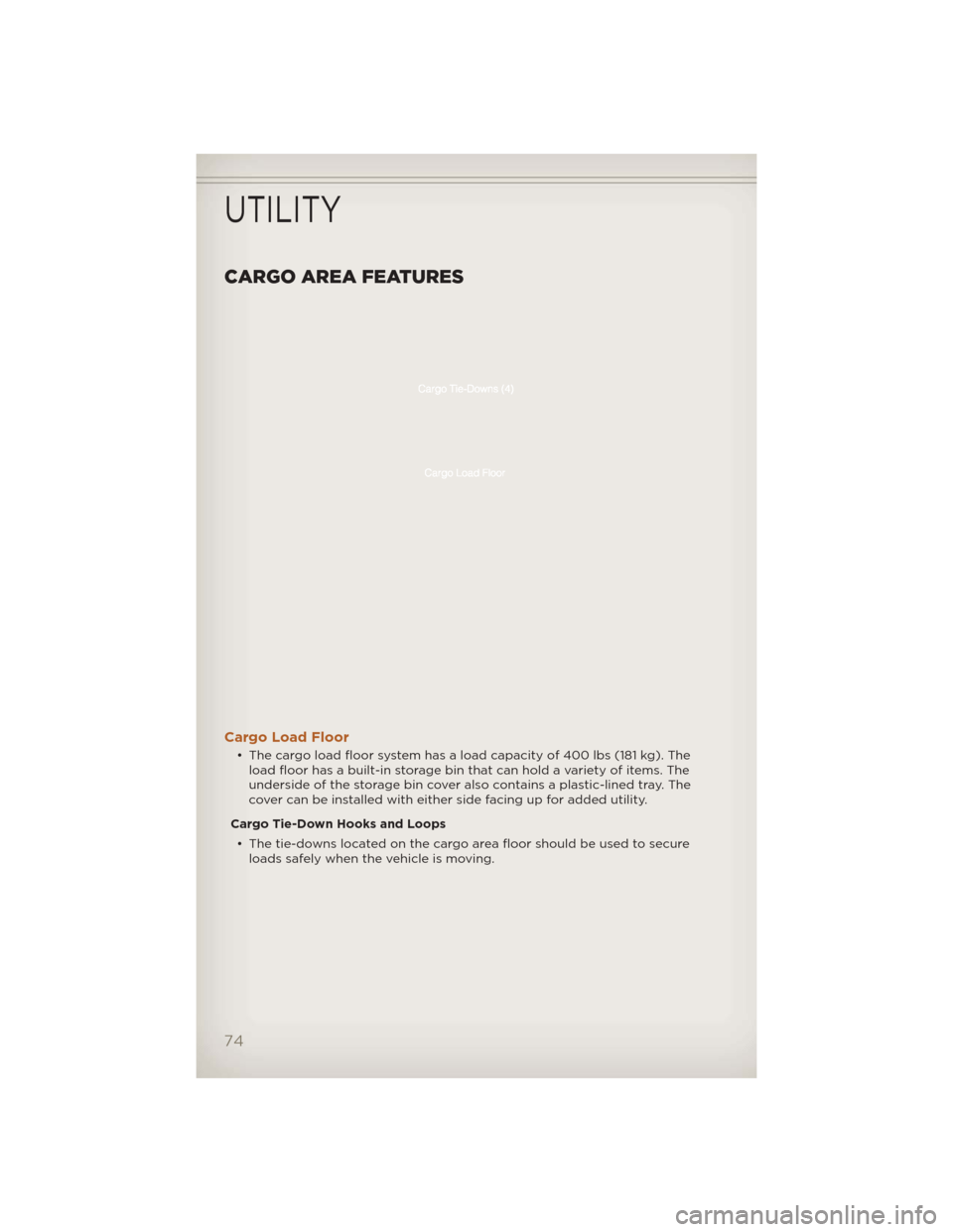
CARGO AREA FEATURES
Cargo Load Floor
• The cargo load floor system has a load capacity of 400 lbs (181 kg). Theload floor has a built-in storage bin that can hold a variety of items. The
underside of the storage bin cover also contains a plastic-lined tray. The
cover can be installed with either side facing up for added utility.
Cargo Tie-Down Hooks and Loops • The tie-downs located on the cargo area floor should be used to secure loads safely when the vehicle is moving.
UTILITY
74
Page 77 of 124
WARNING!
• Cargo tie-downs are not safe anchors for a child seat tether strap. Ina sudden stop or a collision, a tie-down could pull loose and allow
the child seat to come loose. A child could be badly injured. Use
only the anchors provided for child seat tethers.
• To help protect against personal injury, passengers should not be seated in the rear cargo area. The rear cargo space is intended for
load carrying purposes only, not for passengers, who should sit in
seats and use seat belts.
UTILITY
75
Page 78 of 124
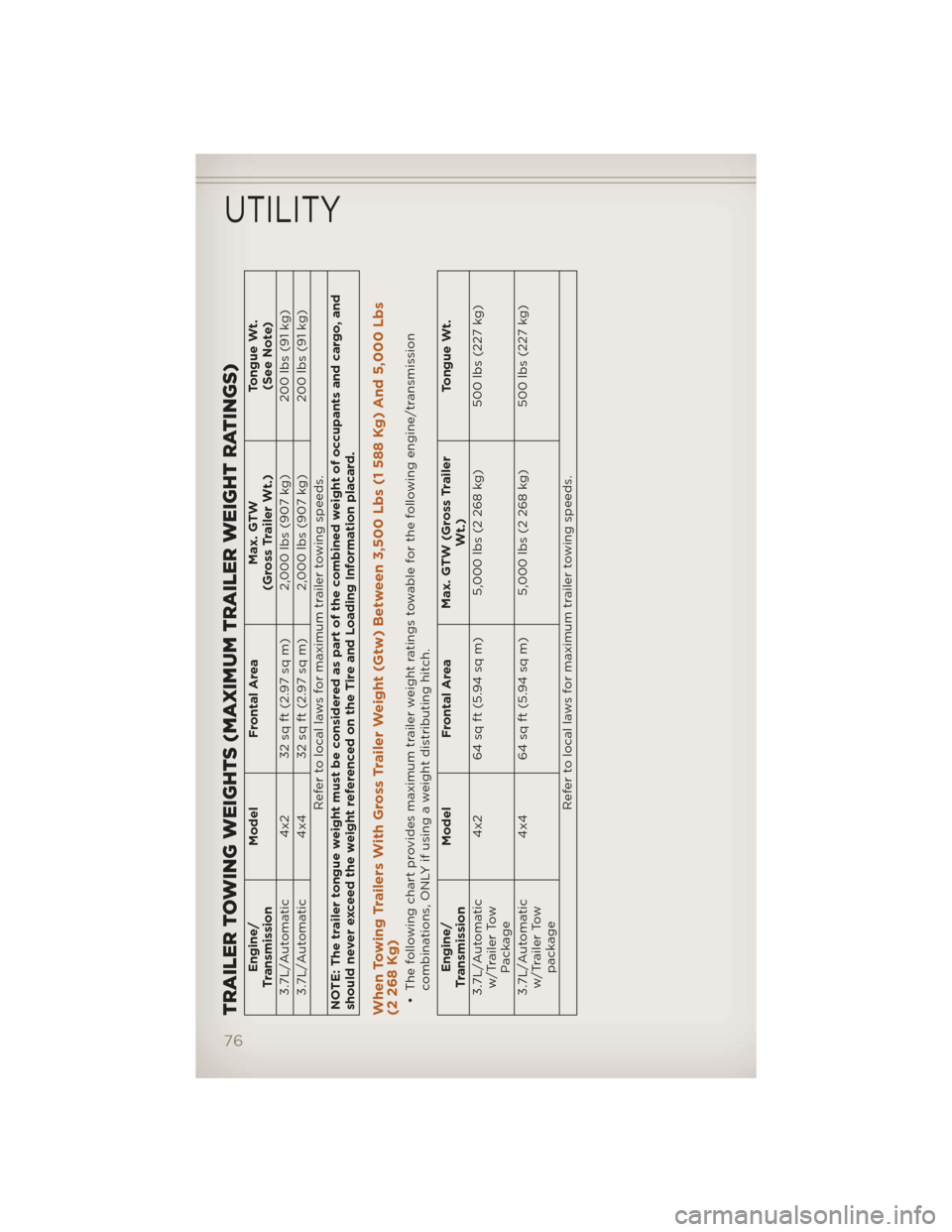
TRAILER TOWING WEIGHTS (MAXIMUM TRAILER WEIGHT RATINGS)
Engine/
Transmission Model
Frontal Area Max. GTW
(Gross Trailer Wt.) Tongue Wt.
(See Note)
3.7L/Automatic 4x2 32 sq ft (2.97 sq m) 2,000 lbs (907 kg) 200 lbs (91 kg)
3.7L/Automatic 4x4 32 sq ft (2.97 sq m) 2,000 lbs (907 kg) 200 lbs (91 kg)
Refer to local laws for maximum trailer towing speeds.
NOTE: The trailer tongue weight must be considered as part of the combined weight of occupants and cargo, and
should never exceed the weight referenced on the Tire and Loading Information placard.
When Towing Trailers With Gross Trailer Weight (Gtw) Between 3,500 Lbs (1 588 Kg) And 5,000 Lbs
(2 268 Kg)• The following chart provides maximum trailer weight ratings towable for the following engine/transmission combinations, ONLY if using a weight distributing hitch.
Engine/
Transmission Model
Frontal Area Max. GTW (Gross Trailer
Wt.) Tongue Wt.
3.7L/Automatic w/Trailer Tow Package 4x2 64 sq ft (5.94 sq m) 5,000 lbs (2 268 kg)
500 lbs (227 kg)
3.7L/Automatic w/Trailer Tow package 4x4 64 sq ft (5.94 sq m) 5,000 lbs (2 268 kg)
500 lbs (227 kg)
Refer to local laws for maximum trailer towing speeds.
UTILITY
76
Page 79 of 124
TOW/HAUL MODE
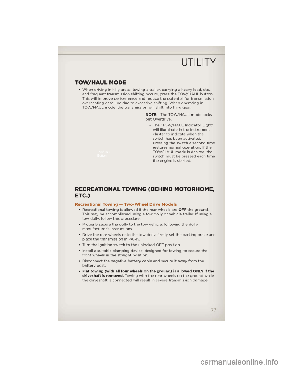
• When driving in hilly areas, towing a trailer, carrying a heavy load, etc.,and frequent transmission shifting occurs, press the TOW/HAUL button.
This will improve performance and reduce the potential for transmission
overheating or failure due to excessive shifting. When operating in
TOW/HAUL mode, the transmission will shift into third gear.
NOTE:The TOW/HAUL mode locks
out Overdrive.
• The “TOW/HAUL Indicator Light”will illuminate in the instrument
cluster to indicate when the
switch has been activated.
Pressing the switch a second time
restores normal operation. If the
TOW/HAUL mode is desired, the
switch must be pressed each time
the engine is started.
RECREATIONAL TOWING (BEHIND MOTORHOME,
ETC.)
Recreational Towing — Two-Wheel Drive Models
• Recreational towing is allowed if the rear wheels are OFFthe ground.
This may be accomplished using a tow dolly or vehicle trailer. If using a
tow dolly, follow this procedure:
• Properly secure the dolly to the tow vehicle, following the dolly manufacturer's instructions.
• Drive the rear wheels onto the tow dolly, firmly set the parking brake and place the transmission in PARK.
• Turn the ignition switch to the unlocked OFF position.
• Install a suitable clamping device, designed for towing, to secure the front wheels in the straight position.
• Disconnect the negative battery cable and secure it away from the battery post.
• Flat towing (with all four wheels on the ground) is allowed ONLY if the
driveshaft is removed. Towing with the rear wheels on the ground while
the driveshaft is connected will result in severe transmission damage.
UTILITY
77
Page 80 of 124
• The parking brakemustbe firmly engaged and the wheels chocked
during driveshaft removal and installation. The parking brake must
remain engaged unless the vehicle is securely and properly connected to
the tow vehicle, or the driveshaft is completely reinstalled. See your
authorized dealer for proper driveshaft removal and reinstallation
procedures, including flange orientation/alignment, use of thread-locking
compound, proper bolt torque specifications, etc.
Towing – Four-Wheel Drive Models
• Depress the brake pedal and turn the ignition switch to ON/RUN
with the engine shut off.
• Shift the transmission into NEUTRAL.
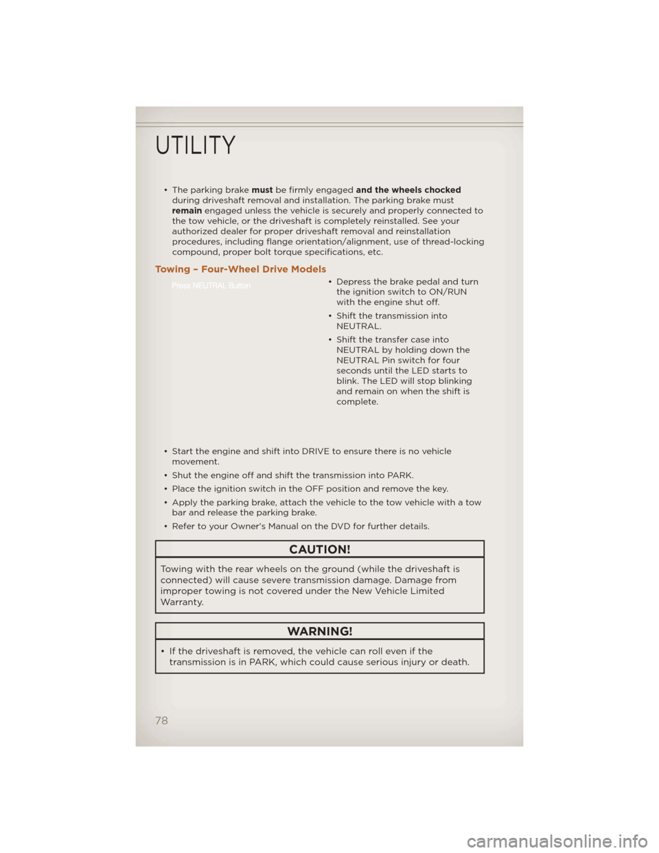
• Shift the transfer case into NEUTRAL by holding down the
NEUTRAL Pin switch for four
seconds until the LED starts to
blink. The LED will stop blinking
and remain on when the shift is
complete.
• Start the engine and shift into DRIVE to ensure there is no vehicle movement.
• Shut the engine off and shift the transmission into PARK.
• Place the ignition switch in the OFF position and remove the key.
• Apply the parking brake, attach the vehicle to the tow vehicle with a tow bar and release the parking brake.
• Refer to your Owner's Manual on the DVD for further details.
CAUTION!
Towing with the rear wheels on the ground (while the driveshaft is
connected) will cause severe transmission damage. Damage from
improper towing is not covered under the New Vehicle Limited
Warranty.
WARNING!
• If the driveshaft is removed, the vehicle can roll even if the transmission is in PARK, which could cause serious injury or death.
UTILITY
78