ECU JEEP PATRIOT 2013 1.G Owner's Manual
[x] Cancel search | Manufacturer: JEEP, Model Year: 2013, Model line: PATRIOT, Model: JEEP PATRIOT 2013 1.GPages: 108, PDF Size: 3.17 MB
Page 63 of 108
• Press and hold the programmed HomeLink®button and observe the indicator
light.
NOTE: • If the indicator light stays on constantly, programming is complete and thegarage door (or device) should activate when the HomeLink
®button is pressed.
• To program the two remaining HomeLink
®buttons, repeat each step for each
remaining button. DO NOT erase the channels.
Using HomeLink®
• To operate, press and release the programmed HomeLink®button. Activation will
now occur for the programmed device (i.e., garage door opener, gate operator,
security system, entry door lock, home/office lighting, etc.,). The hand-held
transmitter of the device may also be used at any time.
WARNING!
• Your motorized door or gate will open and close while you are programming the universal transceiver. Do not program the transceiver if people or pets are in the
path of the door or gate.
• Do not run your vehicle in a closed garage or confined area while programming
the transceiver. Exhaust gas from your vehicle contains Carbon Monoxide (CO)
which is odorless and colorless. Carbon Monoxide is poisonous when inhaled
and can cause you and others to be severely injured or killed.
POWER INVERTER
•A 115 Volt, 150 Watt AC power inverter
is located on the front of the center
console.
• This outlet can power cellular phones, electronics and other low power de-
vices requiring power up to 150 Watts.
NOTE:
The power inverter is designed with
built-in overload protection. If the power
rating of 150 Watts is exceeded, the
power inverter will automatically shut
down. Once the electrical device has been removed from the outlet, the inverter
should automatically reset. If the power rating exceeds approximately 170 Watts, the
power inverter may have to be reset manually. To reset the inverter manually, unplug
the device and plug it in again. To avoid overloading the circuit, check the power
ratings on electrical devices prior to using the inverter.
ELECTRONICS
61
Page 65 of 108
FOUR-WHEEL DRIVE OPERATION
• This vehicle has two full time, on-demand, four-wheel-drive (4WD) systemsavailable, Freedom Drive I and Freedom-Drive II. They provide for all-weather,
all-terrain capability for added driving security in less-than-ideal road conditions.
Freedom-Drive I™ Four Wheel Drive System
• The vehicle will constantly monitor wheel slippage and transfer power to the axle that can use it the most.
• For additional traction in sand, deep snow or loose traction surfaces, the “4WD Lock” sends equal amounts of the torque to the front and rear axles at low speeds.
• To activate, pull the T-handle, located in between the front driver and passenger seats, up once and release. The “4WD Indicator Light” will come on in the cluster.
OFF-ROAD CAPABILITIES
63
Page 75 of 108
• For vehicles equipped with plastictrim, the plastic has been cut away
to expose the jacking locations in
the body.
• Do not raise the vehicle until you are sure the jack is securely engaged.
3. Turn the jack screw to the left until the jack can be placed under the jacking
location. Once the jack is positioned,
turn the jack screw to the right until
the jack head is properly engaged with
the lift area closest to the wheel to be
changed.
4. Using the swivel wrench raise the ve- hicle by turning the jack screw to the
right. Raise the vehicle only until the
tire just clears the surface and enough
clearance is obtained to install the
spare tire. Minimum tire lift provides
maximum stability.
5. Remove the wheel nuts and pull the wheel and wheel covers, where appli-
cable, off the hub. Install the spare
wheel and wheel nuts with the cone
shaped end of the nuts toward the
wheel. Lightly tighten the nuts.
NOTE:
The wheel cover is held on the wheel by
the wheel nuts. When reinstalling the
original wheel, properly align the wheel
cover to the valve stem, place the wheel
cover onto the wheel, then install the
wheel nuts.
6. Lower the vehicle by turning the jack screw to the left.
7.
Finish tightening the nuts. Push down
on the wrench while at the end of the
handle for increased leverage. Tighten
the lug nuts in a star pattern until each
nut has been tightened twice. The
correct wheel nut torque is 100 ft lbs
(135 N·m). If you doubt that you have tightened the nuts correctly, have them
checked with a torque wrench by your authorized dealer or service station.
WHAT TO DO IN EMERGENCIES
73
Page 76 of 108
8. Remove the wheel blocks and lower the jack until it is free. Reassemble the lugwrench to the jack assembly and stow it in the spare tire area. Secure the
assembly using the means provided.
9. Place the deflated (flat) tire in the cargo area, have the tire repaired or replaced as
soon as possible.
10. Check the spare tire pressure as soon as possible. Correct the tire pressure as required.
Road Tire Installation
Vehicles Equipped With Wheel Covers
1. Mount the road tire on the axle.
2. To ease the installation process for steel wheels with wheel covers, install two lugnuts on the mounting studs which are on each side of the valve stem. Install the
lug nuts with the cone shaped end of the nut toward the wheel. Lightly tighten the
lug nuts.
3. Align the valve notch in the wheel cover with the valve stem on the
wheel. Install the cover by hand,
snapping the cover over the two lug
nuts. Do not use a hammer or exces-
sive force to install the cover.
4. Install the remaining lug nuts with the cone shaped end of the nut toward the
wheel. Lightly tighten the lug nuts.
5. Lower the vehicle to the ground by turning the jack handle counterclock-
wise.
6. Finish tightening the lug nuts. Push down on the wrench while at the end
of the handle for increased leverage.
Tighten the lug nuts in a star pattern
until each nut has been tightened twice. The correct tightness of each lug nut is
100 ft/lbs (135 N·m). If in doubt about the correct tightness, have them checked
with a torque wrench by your authorized dealer or service station.
7. After 25 miles (40 km) check the lug nut torque with a torque wrench to ensure that all lug nuts are properly seated against the wheel.
1 — Valve Stem 4 — Wheel Cover
2 — Valve Notch 5 — Mounting Stud
3 — Wheel Lug
Nut
WHAT TO DO IN EMERGENCIES
74
Page 78 of 108
WARNING!
• Being under a jacked-up vehicle is dangerous. The vehicle could slip off thejack and fall on you. You could be crushed. Never put any part of your body
under a vehicle that is on a jack. If you need to get under a raised vehicle, take
it to a service center where it can be raised on a lift.
• Never start or run the engine while the vehicle is on a jack.
• The jack is designed to be used as a tool for changing tires only. The jack
should not be used to lift the vehicle for service purposes. The vehicle should
be jacked on a firm level surface only. Avoid ice or slippery areas.
• Do not attempt to change a tire on the side of the vehicle close to moving
traffic, pull far enough off the road to avoid the danger of being hit when
operating the jack or changing the wheel.
• Carefully follow these tire changing warnings to help prevent personal injury or
damage to your vehicle:
• Always park on a firm, level surface as far from the edge of the roadwayas possible before raising the vehicle.
• Turn on the Hazard Warning flasher.
• Block the wheel diagonally opposite the wheel to be raised.
• Set the parking brake firmly and set an automatic transmission in PARK;
a manual transmission in REVERSE.
• Do not let anyone sit in the vehicle when it is on a jack.
• Do not get under the vehicle when it is on a jack.
• Only use the jack in the positions indicated and for lifting this vehicle during
a tire change.
• If working on or near a roadway, be extremely careful of motor traffic.
• To assure that spare tires, flat or inflated, are securely stowed, spares must be
stowed with the valve stem facing the ground.
• Raising the vehicle higher than necessary can make the vehicle less stable. It
could slip off the jack and hurt someone near it. Raise the vehicle only enough
to remove the tire.
• To avoid possible personal injury, handle the wheel covers with care to avoid
contact with any sharp edges.
• A loose tire or jack thrown forward in a collision or hard stop could injure the
occupants in the vehicle. Have the deflated (flat) tire repaired or replaced
immediately.
• To avoid the risk of forcing the vehicle off the jack, do not tighten the lug nuts
fully until the vehicle is lowered to the ground. Failure to follow this warning
may result in personal injury.
JUMP-STARTING PROCEDURES
• If your vehicle has a discharged battery it can be jump-started using a set of
jumper cables and a battery in another vehicle or by using a portable battery
booster pack. Jump-starting can be dangerous if done improperly so please follow
the procedures in this section carefully.
WHAT TO DO IN EMERGENCIES
76
Page 94 of 108
FUSES
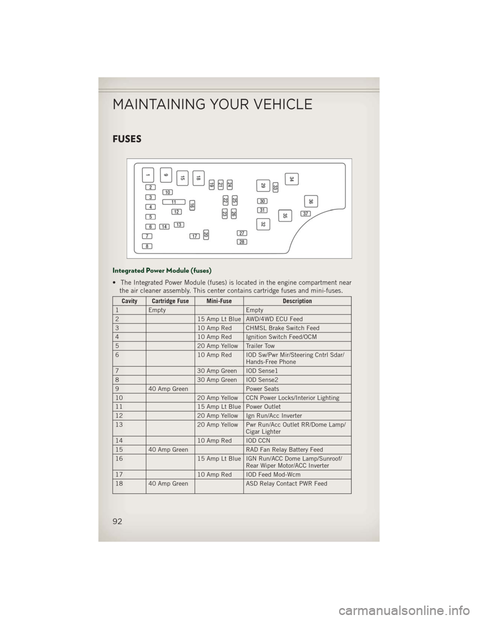
Integrated Power Module (fuses)
• The Integrated Power Module (fuses) is located in the engine compartment nearthe air cleaner assembly. This center contains cartridge fuses and mini-fuses.
Cavity Cartridge Fuse Mini-Fuse Description
1 Empty Empty
2 15 Amp Lt Blue AWD/4WD ECU Feed
3 10 Amp Red CHMSL Brake Switch Feed
4 10 Amp Red Ignition Switch Feed/OCM
5 20 Amp Yellow Trailer Tow
6 10 Amp Red IOD Sw/Pwr Mir/Steering Cntrl Sdar/
Hands-Free Phone
7 30 Amp Green IOD Sense1
8 30 Amp Green IOD Sense2
9 40 Amp Green Power Seats
10 20 Amp Yellow CCN Power Locks/Interior Lighting
11 15 Amp Lt Blue Power Outlet
12 20 Amp Yellow Ign Run/Acc Inverter
13 20 Amp Yellow Pwr Run/Acc Outlet RR/Dome Lamp/
Cigar Lighter
14 10 Amp Red IOD CCN
15 40 Amp Green RAD Fan Relay Battery Feed
16 15 Amp Lt Blue IGN Run/ACC Dome Lamp/Sunroof/
Rear Wiper Motor/ACC Inverter
17 10 Amp Red IOD Feed Mod-Wcm
18 40 Amp Green ASD Relay Contact PWR Feed
MAINTAINING YOUR VEHICLE
92
Page 99 of 108
Airbag..................12
Air Conditioning............25
Alarm,Panic ..............10
Arming Theft System (Security Alarm) ...........11
Automatic Temperature Control (ATC).................25
Automatic Transmission FluidType .............86
Overheating ............71
AxleFluid................86
Belts, Seat ...............11
Brake Fluid ...............86
Break-In Recommendations, New Vehicle .............20
BulbReplacement...........95
Calibration,Compass .........57
ChangeOilIndicator..........70
ChangingAFlatTire..........71
Child Restraint .............13
Child Restraint Tether Anchors ....13
Compass Calibration ..........57
Cooling System Coolant Capacity .........86
Cruise Control (Speed Control) ....23
CruiseLight...............23
Dimmer Control .............21
Dimmer Switch, Headlight ......21
Disarming, Theft System .......11
Electronics
Your Vehicle's Sound System...28
Electronic Speed Control (Cruise Control) ...........23
Electronic Stability Control (ESC)...66
Electronic Vehicle Information Center(EVIC)..........57,58
Emergency, In Case of Brake Warning Light .......68
Jacking ...............71
Jump Starting ...........76
Overheating ............70 Engine
Break-In Recommendations . . .20
Compartment ...........84
Jump Starting ...........76
Oil Selection ............86
Overheating ............70
Event Data Recorder ..........82
Exterior Lights .............95
Flash-To-Pass ..............21
Fluid Capacities ............86
Fluids ..................86
FogLights................21
Folding Front Passenger Seat .....16
FoldingRearSeat ...........17
Four Wheel Drive Operation ......63
Freeing A Stuck Vehicle ........81
Front Heated Seats ...........18
Fuel Filler Cap (Gas Cap) .......69
Specifications ...........86
Garage Door Opener (HomeLink®)...59
Gas Cap (Fuel Filler Cap) .......69
Headlights ................20
Dimmer Switch ..........21
HighBeam .............21
Heated Seats ..............18
High Beam/Low Beam Select (Dimmer) Switch ..........21
HomeLink®(Garage Door Opener)...59
Hood Release ..............83
Instrument Cluster Indicators ..............9
Instrument Cluster Warning Lights . . .8
Intermittent Wipers (Delay Wipers)..22
Introduction ...............2
Inverter Outlet (115V) .........61
Inverter, Power .............61
iPod
®/USB/MP3 Control ........51
Bluetooth Streaming Audio . . .57
Jacking Instructions ..........72
Jack Location ..............71
INDEX
97