turn signal JEEP PATRIOT 2013 1.G User Guide
[x] Cancel search | Manufacturer: JEEP, Model Year: 2013, Model line: PATRIOT, Model: JEEP PATRIOT 2013 1.GPages: 108, PDF Size: 3.17 MB
Page 3 of 108
INTRODUCTION/WELCOME
WELCOME FROM
CHRYSLER GROUP LLC.......... 2
CONTROLS AT A GLANCE
DRIVER COCKPIT............... 6
INSTRUMENT CLUSTER .......... 8
GETTING STARTED
KEYFOB ................... 10
REMOTE START............... 10
THEFT ALARM ................ 11
SEATBELT .................. 11
SUPPLEMENTAL RESTRAINT SYSTEM
(SRS) — AIR BAGS ............ 12
CHILD RESTRAINTS ............ 13
FRONT SEATS ................ 15
REAR SEATS ................ 17
HEATEDSEATS ............... 18
TILT STEERING COLUMN ......... 19
OPERATING YOUR VEHICLE
ENGINE BREAK-IN
RECOMMENDATIONS........... 20
TURN SIGNAL/LIGHTS LEVER ...... 20
WIPER/WASHER LEVER .......... 22
SPEED CONTROL .............. 23
CONTINUOUSLY VARIABLE AUTOMATIC
TRANSMISSION (CVT) ........... 24
MANUAL CLIMATE CONTROLS ...... 24
AUTOMATIC TEMPERATURE
CONTROLS (ATC) .............. 25
POWER SUNROOF ............. 26
WIND BUFFETING ............. 27
ELECTRONICS
YOUR VEHICLE'S SOUND SYSTEM . . . 28
Uconnect®130 ............... 30
Uconnect®130 WITH
SiriusXM SATELLITE RADIO ........ 32
Uconnect
®230 ............... 35
Uconnect®430/430N ........... 38
SiriusXM SATELLITE RADIO/TRAVEL
LINK ...................... 47
STEERING WHEEL AUDIO CONTROLS.. 50
iPod®/USB/MP3 CONTROL ........ 51
Uconnect®Phone .............. 51
Uconnect®VOICE COMMAND ....... 54
Bluetooth®STREAMING AUDIO ..... 57
ELECTRONIC VEHICLE INFORMATION
CENTER (EVIC) ............... 57
PROGRAMMABLE FEATURES ....... 58
UNIVERSAL GARAGE DOOR OPENER
(HomeLink
®) ................. 59
POWER INVERTER ............. 61
POWER OUTLET .............. 62
OFF-ROAD CAPABILITIES
FOUR-WHEEL DRIVE OPERATION . . . 63
UTILITY
TRAILER TOWING WEIGHTS
(MAXIMUM TRAILER WEIGHT
RATINGS).................. 65
RECREATIONAL TOWING
(BEHIND MOTORHOME, ETC.) ..... 65
WHATTODOIN
EMERGENCIES
ROADSIDE ASSISTANCE.......... 66
INSTRUMENT CLUSTER WARNING
LIGHTS .................... 66
IF YOUR ENGINE OVERHEATS ...... 70
AUTOMATIC TRANSMISSION
OVERHEATING ............... 71
JACKING AND TIRE CHANGING ..... 71
JUMP-STARTING PROCEDURES ..... 76
SHIFT LEVER OVERRIDE ......... 79
TOWING A DISABLED VEHICLE ..... 80
FREEING A STUCK VEHICLE ....... 81
EVENT DATA RECORDER (EDR) ..... 82
MAINTAINING YOUR VEHICLE
OPENING THE HOOD........... 83
ENGINE COMPARTMENT ......... 84
FLUIDS AND CAPACITIES ........ 86
MAINTENANCE SCHEDULE ....... 87
MAINTENANCE RECORD ......... 91
FUSES ..................... 92
TIRE PRESSURES ............. 94
WHEEL AND WHEEL TRIM CARE .... 95
EXTERIOR BULBS ............. 95
MOPAR ACCESSORIES
AUTHENTIC ACCESSORIES
BY MOPAR®................. 96
INDEX................... 97
FAQ(HowTo?)
FREQUENTLY ASKED QUESTIONS . . . 100
TABLE OF CONTENTS
Page 9 of 108
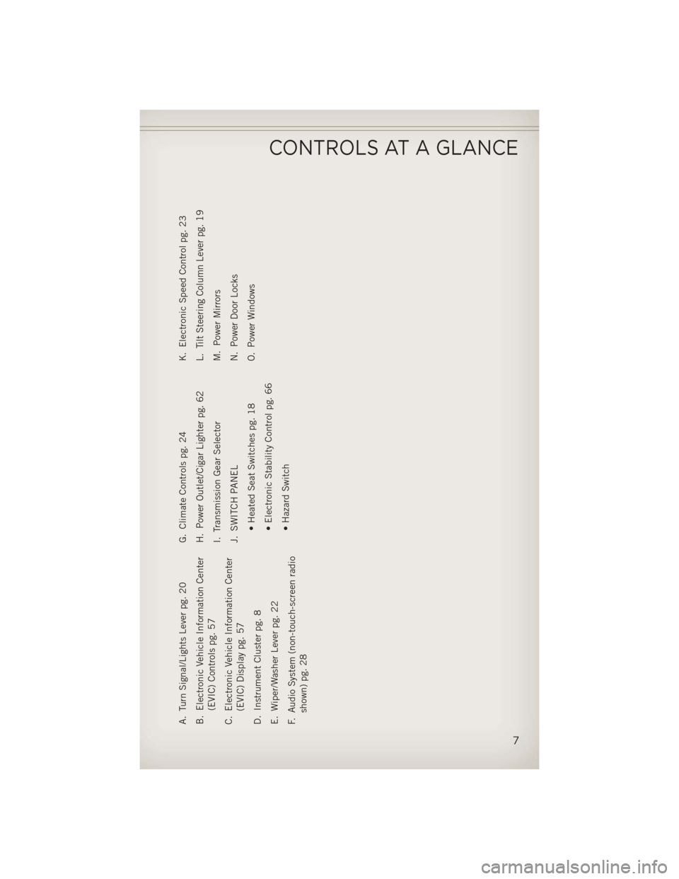
A. Turn Signal/Lights Lever pg. 20
B. Electronic Vehicle Information Center(EVIC) Controls pg. 57
C. Electronic Vehicle Information Center (EVIC) Display pg. 57
D. Instrument Cluster pg. 8
E. Wiper/Washer Lever pg. 22
F. Audio System (non-touch-screen radio shown) pg. 28 G. Climate Controls pg. 24
H. Power Outlet/Cigar Lighter pg. 62
I. Transmission Gear Selector
J. SWITCH PANEL
• Heated Seat Switches pg. 18
• Electronic Stability Control pg. 66
• Hazard Switch K. Electronic Speed Control pg. 23
L. Tilt Steering Column Lever pg. 19
M. Power Mirrors
N. Power Door Locks
O. Power Windows
CONTROLS AT A GLANCE
7
Page 11 of 108
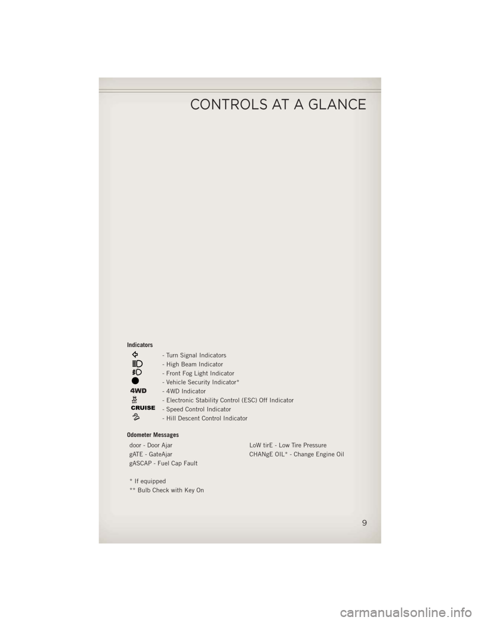
Indicators
- Turn Signal Indicators
- High Beam Indicator
- Front Fog Light Indicator
- Vehicle Security Indicator*
- 4WD Indicator
- Electronic Stability Control (ESC) Off Indicator
- Speed Control Indicator
- Hill Descent Control Indicator
Odometer Messages door - Door Ajar LoW tirE - Low Tire Pressure
gATE - GateAjar CHANgE OIL* - Change Engine Oil
gASCAP - Fuel Cap Fault
* If equipped
** Bulb Check with Key On
CONTROLS AT A GLANCE
9
Page 21 of 108
TILT STEERING COLUMN
• The tilt lever is located on the steeringcolumn, below the turn signal lever.
• Push down on the lever to unlock the steering column.
• With one hand firmly on the steering wheel, move the steering column up or
down as desired.
• Pull upward on the lever to lock the column firmly in place.
WARNING!
Do not adjust the steering column while driving. Adjusting the steering column
while driving, or driving with the steering column unlocked, could cause the driver
to lose control of the vehicle. Be sure the steering column is locked before driving
your vehicle. Failure to follow this warning may result in severe injury or death.
GETTING STARTED
19
Page 22 of 108
ENGINE BREAK-IN RECOMMENDATIONS
• A long break-in period is not required for the engine and drivetrain (transmissionand axle) in your vehicle.
• Drive moderately during the first 300 miles (500 km). After the initial 60 miles (100 km), speeds up to 50 or 55 mph (80 or 90 km/h) are desirable.
• While cruising, brief full-throttle acceleration within the limits of local traffic laws contributes to a good break-in. Wide-open throttle acceleration in low gear can be
detrimental and should be avoided.
• The engine oil installed in the engine at the factory is a high-quality energy conserving type lubricant. Oil changes should be consistent with anticipated
climate conditions under which vehicle operations will occur. For the recom-
mended viscosity and quality grades, refer to “Maintaining Your Vehicle”.
NOTE:
A new engine may consume some oil during its first few thousand miles (kilometers)
of operation. This should be considered a normal part of the break-in and not
interpreted as an indication of difficulty.
CAUTION!
Never use Non-Detergent Oil or Straight Mineral Oil in the engine or damage may
result.
TURN SIGNAL/LIGHTS LEVER
Headlights/Parking Lights
• Rotate the end of the lever to the first detent for parking lightsand to the
second detent for headlights
.
OPERATING YOUR VEHICLE
20
Page 23 of 108
Instrument Panel Dimmer
• Rotate the center portion of the lever to the extreme bottom position to fully dimthe instrument panel lights and prevent the interior lights from illuminating when
a door is opened.
• Rotate the center portion of the lever up to increase the brightness of the instrument panel lights when the parking lights or headlights are on.
• Rotate the center portion of the lever upward to the next detent position to brighten the odometer and radio controls when the parking lights or headlights are
on.
• Rotate the center portion of the lever upward to the last detent to turn on the interior lighting.
Flash To Pass
• Pull the lever toward you to activate the high beams. The high beams will remainon until the lever is released.
High Beam Operation
• Push the lever forward to activate the high beams.
NOTE:
For safe driving, turn off the high beams when oncoming traffic is present to prevent
headlight glare and as a courtesy to other motorists.
Fog Lights
• Turn on the parking lights or low beam headlights and pull out the end of the lever.
Turn Signals/Lane Change Assist
• Tap the lever up or down once and the turn signal (right or left) will flash threetimes and automatically turn off.
OPERATING YOUR VEHICLE
21
Page 56 of 108
Receiving A Call – Accept (And End)
• When an incoming call rings/is announced on Uconnect®, press the Phone button
.
• To end a call, press the Phone button
.
Mute (Or Unmute) Microphone During Call
• During a call, press the “Voice Command” button.
• (After the BEEP), say “mute” (or “mute off”).
Transfer Ongoing Call Between Handset And Vehicle
• During a call, press the “Voice Command” button.
• (After the BEEP), say “transfer call”.
Changing The Volume
• Start a dialogue by pressing the “Phone” button, then adjust the volume
during a normal call.
• Use the radio ON/OFF VOLUME rotary knob to adjust the volume to a comfortable level while the Uconnect
®system is speaking. Please note the volume setting for
Uconnect®is different than the audio system.
WARNING!
• Any voice commanded system should be used only in safe driving conditions
following applicable laws regarding phone use. Your attention should be
focused on safely operating the vehicle. Failure to do so may result in a
collision causing you and others to be severely injured or killed.
• In an emergency, to use Uconnect
®Phone, your mobile phone must be:
• turned on,
• paired to Uconnect
®Phone,
• and have network coverage.
Uconnect® VOICE COMMAND
Voice Command Operation
• The Uconnect®Voice Command system allows you to control your AM, FM radio,
satellite radio, disc player, HDD, Uconnect®Phone, a memo recorder, and
supported portable media devices.
• When you press the “Voice Command” button
located on the radio
faceplate or steering wheel, you will hear a beep. The beep is your signal to give a
command. If you do not say a command within a few seconds, the system will
present you with a list of options. If you ever wish to interrupt the system while it
lists options, press the “Voice Command” button
, listen for the BEEP, and
say your command.
ELECTRONICS
54
Page 61 of 108
Sound Horn With Lock
• To turn the horn chirp on or off when the doors are locked:• Press the LOCK button for at least 4 seconds, but no longer than 10 seconds.
Then, press the PANIC button while still holding the LOCK button.
• Release both buttons at the same time.
Flashing Lights With Lock
• The turn signal lights flashing, when the doors are locked or unlocked, feature can be turned on or off. To turn this feature on or off:• Press and hold the UNLOCK button for at least 4 seconds, but no longer than
10 seconds. Then, press and hold the LOCK button while still holding the
UNLOCK button.
• Release both buttons at the same time.
UNIVERSAL GARAGE DOOR OPENER (HomeLink®)
• HomeLink®replaces up to three hand-held transmitters that operate devices such
as garage door openers, motorized gates, lighting or home security systems. The
HomeLink
®unit is powered by your vehicles 12 Volt battery.
• The HomeLink
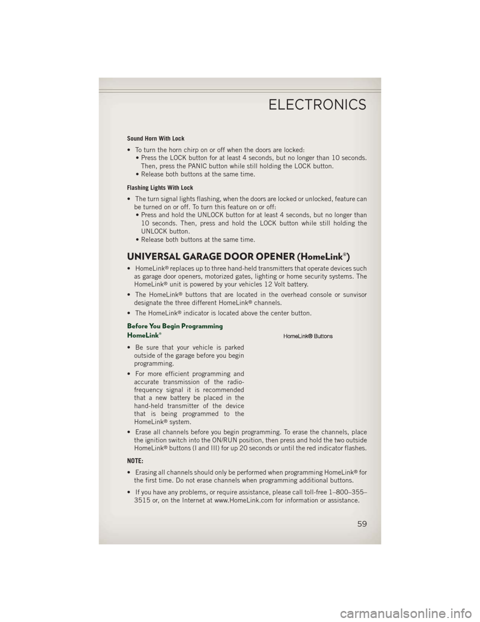
®buttons that are located in the overhead console or sunvisor
designate the three different HomeLink®channels.
• The HomeLink
®indicator is located above the center button.
Before You Begin Programming
HomeLink®
• Be sure that your vehicle is parked outside of the garage before you begin
programming.
• For more efficient programming and accurate transmission of the radio-
frequency signal it is recommended
that a new battery be placed in the
hand-held transmitter of the device
that is being programmed to the
HomeLink
®system.
• Erase all channels before you begin programming. To erase the channels, place the ignition switch into the ON/RUN position, then press and hold the two outside
HomeLink
®buttons (I and III) for up 20 seconds or until the red indicator flashes.
NOTE:
• Erasing all channels should only be performed when programming HomeLink
®for
the first time. Do not erase channels when programming additional buttons.
• If you have any problems, or require assistance, please call toll-free 1–800–355– 3515 or, on the Internet at www.HomeLink.com for information or assistance.
ELECTRONICS
59
Page 62 of 108
Programming A Rolling Code
• For programming Garage Door Openers that were manufactured after 1995. TheseGarage Door Openers can be identified by the “LEARN” or “TRAIN” button located
where the hanging antenna is attached to the Garage Door Opener. It is NOT the
button that is normally used to open and close the door. The name and color of the
button may vary by manufacturer.
• Place the ignition switch into the ON/RUN position.
• Place the hand-held transmitter 1 to 3 in (3 to 8 cm) away from the HomeLink
®
button you wish to program while keeping the HomeLink®indicator light in view.
• Simultaneously press and hold both the HomeLink
®button you want to program
and the hand-held transmitter button.
• Continue to hold both buttons and observe the indicator light. The HomeLink
®
indicator will flash slowly and then rapidly after HomeLink®has received the
frequency signal from the hand-held transmitter. Release both buttons after the
indicator light changes from slow to rapid.
• At the garage door opener motor (in the garage), locate the “LEARN” or “TRAIN- ING” button. This can usually be found where the hanging antenna wire is
attached to the garage door opener motor. Firmly press and release the “LEARN”
or “TRAINING” button.
NOTE:
You have 30 seconds in which to initiate the next step after the LEARN button has
been pressed.
• Return to the vehicle and press the programmed HomeLink
®button twice
(holding the button for two seconds each time). If the device is plugged in and
activates, programming is complete.
NOTE:
If the device does not activate, press the button a third time (for two seconds) to
complete the training.
• To program the remaining two HomeLink
®buttons, repeat each step for each
remaining button. DO NOT erase the channels.
Programming A Non-Rolling Code
• For programming Garage Door Openers manufactured before 1995.
• Turn the ignition switch to the ON/RUN position.
• Place the hand-held transmitter 1 to 3 in (3 to 8 cm) away from the HomeLink
®
button you wish to program while keeping the HomeLink®indicator light in view.
• Simultaneously press and hold both the HomeLink
®button you want to program
and the hand-held transmitter button.
• Continue to hold both buttons and observe the indicator light. The HomeLink
®
indicator will flash slowly and then rapidly after HomeLink®has received the
frequency signal from the hand-held transmitter. Release both buttons after the
indicator light changes from slow to rapid.
ELECTRONICS
60
Page 69 of 108
NOTE:
AFTER INFLATION, THE VEHICLE MAY NEED TO BE DRIVEN FOR 20 MINUTES
BEFORE THE FLASHING LIGHT WILL TURN OFF.
• Please note that the TPMS is not a substitute for proper tire maintenance, and itis the driver’s responsibility to maintain correct tire pressure, even if under-
inflation has not reached the level to trigger illumination of the TPMS low tire
pressure telltale.
• Your vehicle has also been equipped with a TPMS malfunction indicator to indicate when the system is not operating properly. The TPMS malfunction
indicator is combined with the low tire pressure telltale. When the system detects
a malfunction, the telltale will flash for approximately one minute and then remain
continuously illuminated. This sequence will continue each time the vehicle is
restarted as long as the malfunction exists.
• When the malfunction indicator is illuminated, the system may not be able to detect or signal low tire pressure as intended. TPMS malfunctions may occur for a
variety of reasons, including the installation of replacement or alternate tires or
wheels on the vehicle that prevent the TPMS from functioning properly. Always
check the TPMS malfunction telltale after replacing one or more tires or wheels on
your vehicle, to ensure that the replacement or alternate tires and wheels allow the
TPMS to continue to function properly.
NOTE:
Tire pressures change by approximately 1 psi (7 kPa) per 12° F (7° C) of air
temperature change. Keep this in mind when checking tire pressure inside a garage,
especially in the Winter. Example: If garage temperature is 68°F (20°C) and the
outside temperature is 32°F (0°C), then the cold tire inflation pressure should be
increased by 3 psi (21 kPa), which equals 1 psi (7 kPa) for every 12°F (7°C) for this
outside temperature condition.
CAUTION!
The TPMS has been optimized for the original equipment tires and wheels. TPMS
pressures and warning have been established for the tire size equipped on your
vehicle. Undesirable system operation or sensor damage may result when using
replacement equipment that is not of the same size, type, and/or style. Aftermar-
ket wheels can cause sensor damage. Do not use tire sealant from a can, or
balance beads if your vehicle is equipped with a TPMS, as damage to the sensors
may result.
- Engine Temperature Warning Light
• This light warns of an overheated engine condition.
• If the light turns on and a warning chime sounds while driving, safely pull over and stop the vehicle. If the A/C system is on, turn it off. Also, shift the transmission into
NEUTRAL and idle the vehicle. If the temperature reading does not return to
normal, turn the engine off immediately.
WHAT TO DO IN EMERGENCIES
67