clock JEEP PATRIOT 2017 1.G Owners Manual
[x] Cancel search | Manufacturer: JEEP, Model Year: 2017, Model line: PATRIOT, Model: JEEP PATRIOT 2017 1.GPages: 421, PDF Size: 3.4 MB
Page 24 of 421
NOTE:If you try to remove the key before you place the
gear selector in PARK, the key may become trapped tempo-
rarily in the ignition. If this occurs, place the gear selector in
PARK, rotate the key clockwise slightly, and then remove the
key as described above. If a malfunction occurs, the system
will trap the key in the ignition to warn you that this safety
feature is inoperable. The engine can be started and stopped
but the key cannot be removed until you obtain service.
WARNING!
• Before exiting a vehicle, always shift the automatic
transmission into PARK or the manual transmission
into FIRST gear or REVERSE, apply the parking
brake, turn the engine OFF, remove the key fob from
the ignition and lock your vehicle.
• Never leave children alone in a vehicle, or with
access to an unlocked vehicle.
• Allowing children to be in a vehicle unattended is
dangerous for a number of reasons. A child or others
could be seriously or fatally injured. Children
should be warned not to touch the parking brake,
brake pedal or the gear selector.
• Do not leave the key fob in or near the vehicle, or in
a location accessible to children. A child could oper-
ate power windows, other controls, or move the
vehicle.
• Do not leave children or animals inside parked
vehicles in hot weather. Interior heat build-up may
cause serious injury or death.
Ignition Positions
1 — LOCK
2 — ACC (ACCESSORY)
3 — ON/RUN
4 — START 22 GETTING TO KNOW YOUR VEHICLE
Page 54 of 421
Windshield Wiper Operation
Rotate the end of the lever upward to the second detent
past the intermittent settings for low-speed wiper opera-
tion. Rotate the end of the lever upward to the third detent
past the intermittent settings for high-speed wiper opera-
tion.
Intermittent Wiper System
Use the intermittent wiper when weather conditions make
a single wiping cycle, with a variable pause between cycles,
desirable. Select the delay interval by turning the end of the
lever. Rotate the end of the lever upward (clockwise) to
decrease the delay time and downward (counterclockwise)
to increase the delay time. The delay can be regulated from
a maximum of approximately 18 seconds between cycles,
to a cycle every second.
NOTE:The wiper delay times depend on vehicle speed. If
the vehicle is moving less than 10 mph (16 km/h), delay
times will be doubled.
Windshield Washers
To use the washer, pull the control lever toward you and
hold while spray is desired. If the lever is pulled while in
the delay range, the wiper will operate in low-speed while
the lever is pulled and for two wipe cycles after the lever is
released, and then resume the intermittent interval previ-
ously selected.
If the lever is pulled while in the off position, the wipers
will operate for two wipe cycles, then turn off.
Windshield Wiper Operation
52 GETTING TO KNOW YOUR VEHICLE
Page 57 of 421
CLIMATE CONTROLS
The Climate Control System allows you to regulate the
temperature, airflow, and direction of air circulating
throughout the vehicle. The controls are located on the
instrument panel below the radio.
Manual Climate Controls
The controls for the manual heating and air conditioning
system in this vehicle consist of a series of outer rotary
dials and inner push knobs. These comfort controls can be
set to obtain desired interior conditions.
Manual Climate Control Descriptions
IconDescription
Blower Control
There are seven blower speeds. Use this control to regulate the amount of air forced through the
system in any mode you select. The blower speed increases as you move the control clockwise
from the off position.
NOTE:Depending on the configuration, your vehicle may be equipped with four blower
speeds.
Manual Climate Controls
3
GETTING TO KNOW YOUR VEHICLE 55
Page 58 of 421
IconDescription
A/C Button
Press and release to change the current setting, the indicator illuminates when A/C is on. Per-
forming this function again will cause the A/C operation to switch into manual mode and the
A/C indicator will turn off.
Temperature Control
Use this control to regulate the temperature of the air inside the passenger compartment. Rotat-
ing the knob counterclockwise, from top center into the blue area of the scale, indicates cooler
temperatures. Rotating the knob clockwise, into the red area, indicates warmer temperatures.
Modes Control
Turn the knob to adjust airflow distribution. The airflow distribution mode can be adjusted so
air comes from the instrument panel outlets, floor outlets, defrost outlets and demist outlets.
Panel Mode
Panel Mode
Air comes from the outlets in the instrument panel. Each of these outlets can be individually
adjusted to direct the flow of air. The air vanes of the center outlets and outboard outlets can be
moved up and down or side to side to regulate airflow direction. There is a shut off wheel lo-
cated below the air vanes to shut off or adjust the amount of airflow from these outlets.
Bi-Level Mode
Bi-Level Mode
Air comes from the instrument panel outlets and floor outlets. A slight amount of air is directed
through the defrost and side window demister outlets.
NOTE: BI-LEVEL mode is designed under comfort conditions to provide cooler air out of the
panel outlets and warmer air from the floor outlets.
56 GETTING TO KNOW YOUR VEHICLE
Page 61 of 421
Automatic Climate Control Descriptions
IconDescription
Blower Control
There are seven blower speeds. Use this control to regulate the amount of air forced through the
system in any mode you select. The blower speed increases as you move the control clockwise
from the OFF position.
NOTE:Depending on the configuration, your vehicle may be equipped with four blower
speeds.
AUTO Setting
Automatically controls the interior cabin temperature by adjusting airflow distribution and
amount. Performing this function will cause the system to switch between manual mode and
automatic modes. Refer to “Automatic Operation” for more information.
A/C Button
Press and release to change the current setting, the indicator illuminates when A/C is ON. Per-
forming this function again will cause the A/C operation to switch into manual mode and the
A/C indicator will turn off.
Temperature Control
Use this control to regulate the temperature of the air inside the passenger compartment. Rotat-
ing the knob counterclockwise, from top center into the blue area of the scale, indicates cooler
temperatures. Rotating the knob clockwise, into the red area, indicates warmer temperatures.
3
GETTING TO KNOW YOUR VEHICLE 59
Page 247 of 421
Fog Lamps
1. Access lamp through the lower fascia cutout.
2. Remove electrical connector from bulb.
3. Remove bulb from housing.
CAUTION!
Do not touch the new bulb with your fingers. Oil
contamination will severely shorten bulb life. If the
bulb comes in contact with any oily surface, clean the
bulb with rubbing alcohol.
Rear Tail, Turn Signal And Backup Lamps
1. Raise the liftgate.
2. Remove the two push-pins from the taillamp housing.
3. Grasp the taillamp and pull firmly to disengage the lightfrom the aperture panel.
4. Twist and remove socket from the light.
5. Remove bulb from socket and replace.
License Lamps
1. Use a screw driver to gently pry against the side of the snap tab to remove the lamp from the liftgate.
2. Rotate the socket 1/4 turn counterclockwise.
3. Pull the bulb from the socket.
Center High-Mounted Stoplamp
This light is an LED assembly. See your authorized dealer
for replacement.
FUSES
WARNING!
• When replacing a blown fuse, always use an appro-
priate replacement fuse with the same amp rating as
the original fuse. Never replace a fuse with another
fuse of higher amp rating. Never replace a blown
fuse with metal wires or any other material. Failure
to use proper fuses may result in serious personal
injury, fire and/or property damage.
(Continued)
7
IN CASE OF EMERGENCY 245
Page 248 of 421
WARNING!(Continued)
•Before replacing a fuse, make sure that the ignition is
off and that all the other services are switched off
and/or disengaged.
• If the replaced fuse blows again, contact an autho-
rized dealer.
• If a general protection fuse for safety systems (air
bag system, braking system), power unit systems
(engine system, gearbox system) or steering system
blows, contact an authorized dealer.
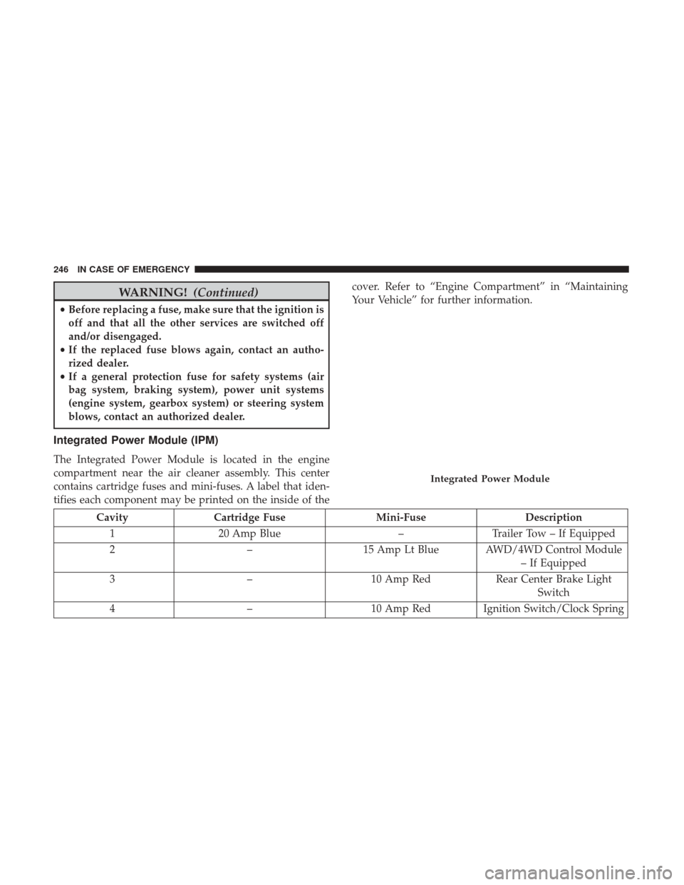
Integrated Power Module (IPM)
The Integrated Power Module is located in the engine
compartment near the air cleaner assembly. This center
contains cartridge fuses and mini-fuses. A label that iden-
tifies each component may be printed on the inside of the cover. Refer to “Engine Compartment” in “Maintaining
Your Vehicle” for further information.
Cavity
Cartridge Fuse Mini-FuseDescription
1 20 Amp Blue –Trailer Tow – If Equipped
2 –15 Amp Lt Blue AWD/4WD Control Module
– If Equipped
3 –10 Amp Red Rear Center Brake Light
Switch
4 –10 Amp Red Ignition Switch/Clock Spring
Integrated Power Module
246 IN CASE OF EMERGENCY
Page 259 of 421
WARNING!
To avoid the risk of forcing the vehicle off the jack, do
not tighten the lug nuts fully until the vehicle has been
lowered. Failure to follow this warning may result in
serious injury.
4. Lower the vehicle to the ground by turning the jack handle counterclockwise.
5. Finish tightening the lug nuts. Push down on the wrench while at the end of the handle for increased
leverage. Refer to “Torque Specifications” in “Technical
Specifications” for correct lug nut torque.
6. After 25 miles (40 km) check the lug nut torque with a torque wrench to ensure that all lug nuts are properly
seated against the wheel.
Vehicles Without Wheel Covers
1. Mount the road tire on the axle.
2.
Install the remaining lug nuts with the cone shaped end of
the nut toward the wheel. Lightly tighten the lug nuts.
WARNING!
To avoid the risk of forcing the vehicle off the jack, do
not fully tighten the lug nuts until the vehicle has been
lowered. Failure to follow this warning may result in
serious injury.
3. Lower the vehicle to the ground by turning the jack handle counterclockwise.
4. Finish tightening the lug nuts. Push down on the wrench while at the end of the handle for increased
leverage. Refer to “Torque Specifications” in “Technical
Specifications” for correct lug nut torque.
5. After 25 miles (40 km) check the lug nut torque with a torque wrench to ensure that all lug nuts are properly
seated against the wheel.
7
IN CASE OF EMERGENCY 257
Page 343 of 421
RADIO 130
Operating Instructions — Radio Mode
NOTE:The ignition switch must be in the ON/RUN or
ACC position to operate the radio.
Power Switch/Volume Control (Rotary)
Push the ON/VOLUME control knob to turn on the radio.
Push the ON/VOLUME control knob a second time to turn
off the radio.
Electronic Volume Control
The electronic volume control turns continuously (360
degrees) in either direction, without stopping. Turning the
ON/VOLUME control knob to the right increases the
volume, and to the left decreases it.
When the audio system is turned on, the sound will be set
at the same volume level as last played.
SEEK Buttons
Push and release the SEEK buttons to search for the next
listenable station in AM/FM mode. Push the right switch
to seek up and the left switch to seek down. The radio will
remain tuned to the new station until you make another
selection. Holding either button will bypass stations with-
out stopping, until you release it.
Clock Setting Procedure
1. Push and hold the TIME button until the hours blink.
2. Adjust the hours by turning the right side TUNE/ SCROLL control knob.
3. After adjusting the hours, push the right side TUNE/ SCROLL control knob to set the minutes. The minutes
will begin to blink.
Radio 130
10
MULTIMEDIA 341
Page 344 of 421
4. Adjust the minutes using the right side TUNE/SCROLLcontrol knob. Push the TUNE/SCROLL control knob to
save time change.
5. To exit, push any button/knob, or wait five seconds.
RW/FF
Pushing the RW (Rewind) or FF (Fast Forward) buttons
causes the tuner to search for the next frequency in the
direction of the arrows. This feature operates in either AM
or FM frequencies.
TUNE Control
Turn the rotary TUNE/SCROLL control knob clockwise to
increase or counterclockwise to decrease the frequency.
Setting The Tone, Balance And Fade
Push the rotary TUNE/SCROLL control knob and BASS
will display. Turn the TUNE/SCROLL control knob to the
right or left to increase or decrease the bass tones.
Push the rotary TUNE/SCROLL control knob a second
time and MID will display. Turn the TUNE/SCROLL
control knob to the right or left to increase or decrease the
mid-range tones. Push the rotary TUNE/SCROLL control knob a third time
and TREBLE will display. Turn the TUNE/SCROLL control
knob to the right or left to increase or decrease the treble
tones.
Push the rotary TUNE/SCROLL control knob a fourth time
and BALANCE will display. Turn the TUNE/SCROLL
control knob to the right or left to adjust the sound level
from the right or left side speakers.
Push the rotary TUNE/SCROLL control knob a fifth time
and FADE will display. Turn the TUNE/SCROLL control
knob to the left or right to adjust the sound level between
the front and rear speakers.
Push the rotary TUNE/SCROLL control knob again to exit
setting tone, balance, and fade.AM/FM Button
Push the buttons to select either AM or FM mode.
SET/RND Button — To Set The Pushbutton Memory
When you are receiving a station that you wish to commit
to pushbutton memory, push the SET/RND button. The
symbol SET 1 will now show in the display window. Select
the button (1 to 6) you wish to lock onto this station and
push and release that button. If a button is not selected
342 MULTIMEDIA