light JEEP PATRIOT 2019 Owner handbook (in English)
[x] Cancel search | Manufacturer: JEEP, Model Year: 2019, Model line: PATRIOT, Model: JEEP PATRIOT 2019Pages: 332, PDF Size: 1.99 MB
Page 236 of 332
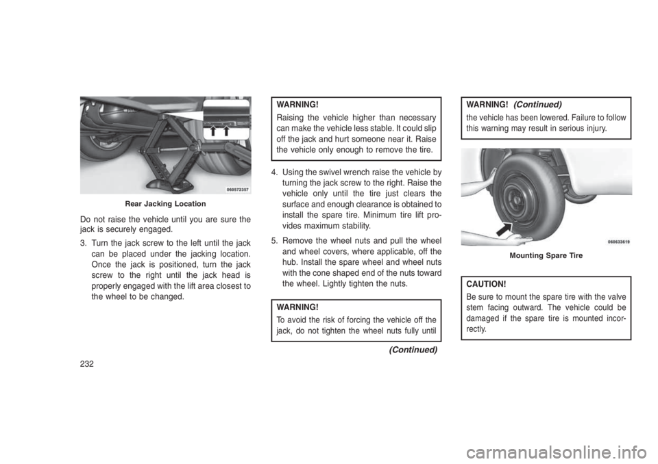
Do not raise the vehicle until you are sure the
jack is securely engaged.
3. Turn the jack screw to the left until the jack
can be placed under the jacking location.
Once the jack is positioned, turn the jack
screw to the right until the jack head is
properly engaged with the lift area closest to
the wheel to be changed.
WARNING!
Raising the vehicle higher than necessary
can make the vehicle less stable. It could slip
off the jack and hurt someone near it. Raise
the vehicle only enough to remove the tire.
4. Using the swivel wrench raise the vehicle by
turning the jack screw to the right. Raise the
vehicle only until the tire just clears the
surface and enough clearance is obtained to
install the spare tire. Minimum tire lift pro-
vides maximum stability.
5. Remove the wheel nuts and pull the wheel
and wheel covers, where applicable, off the
hub. Install the spare wheel and wheel nuts
with the cone shaped end of the nuts toward
the wheel. Lightly tighten the nuts.
WARNING!
To avoid the risk of forcing the vehicle off the
jack, do not tighten the wheel nuts fully until
(Continued)
WARNING!(Continued)
the vehicle has been lowered. Failure to follow
this warning may result in serious injury.
CAUTION!
Be sure to mount the spare tire with the valve
stem facing outward. The vehicle could be
damaged if the spare tire is mounted incor-
rectly.
Rear Jacking Location
Mounting Spare Tire
232
Page 238 of 332
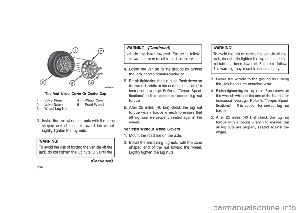
3. Install the five wheel lug nuts with the cone
shaped end of the nut toward the wheel.
Lightly tighten the lug nuts.
WARNING!
To avoid the risk of forcing the vehicle off the
jack, do not tighten the lug nuts fully until the
(Continued)
WARNING!(Continued)
vehicle has been lowered. Failure to follow
this warning may result in serious injury.
4. Lower the vehicle to the ground by turning
the jack handle counterclockwise.
5. Finish tightening the lug nuts. Push down on
the wrench while at the end of the handle for
increased leverage. Refer to “Torque Speci-
fications” in this section for correct lug nut
torque.
6. After 25 miles (40 km) check the lug nut
torque with a torque wrench to ensure that
all lug nuts are properly seated against the
wheel.
Vehicles Without Wheel Covers
1. Mount the road tire on the axle.
2. Install the remaining lug nuts with the cone
shaped end of the nut toward the wheel.
Lightly tighten the lug nuts.
WARNING!
To avoid the risk of forcing the vehicle off the
jack, do not fully tighten the lug nuts until the
vehicle has been lowered. Failure to follow
this warning may result in serious injury.
3. Lower the vehicle to the ground by turning
the jack handle counterclockwise.
4. Finish tightening the lug nuts. Push down on
the wrench while at the end of the handle for
increased leverage. Refer to “Torque Speci-
fications” in this section for correct lug nut
torque.
5. After 25 miles (40 km) check the lug nut
torque with a torque wrench to ensure that
all lug nuts are properly seated against the
wheel.
Tire And Wheel Cover Or Center Cap
1 — Valve Stem 4 — Wheel Cover
2 — Valve Notch 5 — Road Wheel
3 — Wheel Lug Nut
234
Page 259 of 332
ONBOARD DIAGNOSTIC
SYSTEM — OBD II
Your vehicle is equipped with a sophisticated
onboard diagnostic system called OBD II. This
system monitors the performance of the emis-
sions, engine, and automatic transmission con-
trol systems. When these systems are operat-
ing properly, your vehicle will provide excellent
performance and fuel economy, as well as
engine emissions well within current govern-
ment regulations.
If any of these systems require service, the
OBD II system will turn on the “Malfunction
Indicator Light” (MIL). It will also store diagnos-
tic codes and other information to assist your
service technician in making repairs. Although
your vehicle will usually be drivable and not
need towing, see your authorized dealer for
service as soon as possible.
CAUTION!
•Prolonged driving with the MIL on could
cause further damage to the emission con-
trol system. It could also affect fuel
economy and driveability. The vehicle
must be serviced before any emissions
tests can be performed.
•If the MIL is flashing while the engine is
running, severe catalytic converter dam-
age and power loss will soon occur. Imme-
diate service is required.
Onboard Diagnostic System (OBD II)
Cybersecurity
Your vehicle is required to have an Onboard
Diagnostic system (OBD II) and a connection
port to allow access to information related to the
performance of your emissions controls. Autho-
rized service technicians may need to access
this information to assist with the diagnosis and
service of your vehicle and emissions system.
WARNING!
•ONLY an authorized service technician
should connect equipment to the OBD II
connection port in order to diagnose or
service your vehicle.
•If unauthorized equipment is connected to
the OBD II connection port, such as a
driver-behavior tracking device, it may:
•Be possible that vehicle systems, in-
cluding safety related systems, could be
impaired or a loss of vehicle control
could occur that may result in an acci-
dent involving serious injury or death.
•Access, or allow others to access, infor-
mation stored in your vehicle systems,
including personal information.
For further information, refer to “Cybersecurity”
in the “Understanding Your Instrument Panel”
section.
255
Page 260 of 332
Loose Fuel Filler Cap MessageAfter fuel is added, the vehicle diagnostic sys-
tem can determine if the fuel filler cap is possi-
bly loose or improperly installed. A “gASCAP”
message will be displayed in the instrument
cluster. Tighten the gas cap until a “clicking”
sound is heard. This is an indication that the gas
cap is properly tightened. Push the trip odom-
eter RESET button to turn off the message. If
the problem persists, the message will appear
the next time the vehicle is started. This might
indicate a damaged cap. If the problem is
detected twice in a row, the system will turn on
the MIL. Resolving the problem will turn the MIL
light off.
REPLACEMENT PARTS
Use of genuine MOPAR parts for normal/
scheduled maintenance and repairs is highly
recommended to ensure the designed perfor-
mance. Damage or failures caused by the use
of non-MOPAR parts for maintenance and re-
pairs will not be covered by the New Vehicle
Limited Warranty.
MAINTENANCE PROCEDURES
The pages that follow contain therequired
maintenance services determined by the engi-
neers who designed your vehicle.
Besides those maintenance items specified in
the fixed “Maintenance Schedule”, there are
other components which may require servicing
or replacement in the future.
CAUTION!
•Failure to properly maintain your vehicle or
perform repairs and service when neces-
sary could result in more costly repairs,
damage to other components or negatively
impact vehicle performance. Immediately
have potential malfunctions examined by
an authorized dealer or qualified repair
center.
(Continued)
CAUTION!(Continued)
•Your vehicle has been built with improved
fluids that protect the performance and
durability of your vehicle and also allow
extended maintenance intervals. Do not
use chemical flushes in these components
as the chemicals can damage your engine,
transmission, or air conditioning. Such
damage is not covered by the New Vehicle
Limited Warranty. If a flush is needed
because of component malfunction, use
only the specified fluid for the flushing
procedure.
Engine Oil
Checking Oil Level
To assure proper engine lubrication, the engine
oil must be maintained at the correct level.
Check the oil level at regular intervals, such as
every fuel stop.
The best time to check the engine oil level is
about five minutes after a fully warmed engine is
shut off. Do not check oil level before starting
256
Page 270 of 332
•If frequent engine coolant (antifreeze) addi-
tions are required, the cooling system should
be pressure tested for leaks.
•Maintain engine coolant (antifreeze) concen-
tration at a minimum of 50% OAT coolant
(conforming to MS.90032) and distilled water
for proper corrosion protection of your engine
which contains aluminum components.
•Make sure that the coolant expansion bottle
overflow hoses are not kinked or obstructed.
•Keep the front of the radiator clean. If your
vehicle is equipped with air conditioning,
keep the front of the condenser clean.
•Do not change the thermostat for Summer or
Winter operation. If replacement is ever nec-
essary, install ONLY the correct type thermo-
stat. Other designs may result in unsatisfac-
tory engine coolant (antifreeze) performance,
poor gas mileage, and increased emissions.
Brake SystemIn order to assure brake system performance,
all brake system components should be in-spected periodically. Refer to the “Maintenance
Schedule” for the proper maintenance intervals.
WARNING!
Riding the brakes can lead to brake failure
and possibly a collision. Driving with your
foot resting or riding on the brake pedal can
result in abnormally high brake tempera-
tures, excessive lining wear, and possible
brake damage. You would not have your full
braking capacity in an emergency.
Brake Master Cylinder
The fluid level in the master cylinder should be
checked when performing under hood services,
or immediately if the brake system warning light
is on.
Be sure to clean the top of the master cylinder
area before removing the cap. If necessary, add
fluid to bring the fluid level up to the require-
ments described on the brake fluid reservoir.
Fluid level can be expected to fall as the brake
pads wear. The brake fluid level should be
checked when the pads are replaced. However,low fluid level may be caused by a leak and a
checkup may be needed.
NOTE:
If your vehicle is equipped with a manual
transmission, the brake fluid reservoir sup-
plies fluid to both the brake system and the
clutch release system. The two systems are
separated in the reservoir, and a leak in one
system will not affect the other system. The
manual transmission clutch release system
should not require fluid replacement during
the life of the vehicle. If the brake fluid
reservoir is low and the brake system does
not indicate any leaks or other problems, it
may be a result of a leak in the hydraulic
clutch release system. See your local autho-
rized dealer for service.
Use only manufacturer’s recommended brake
fluid. Refer to “Fluids, Lubricants, And Genuine
Parts” in “Maintaining Your Vehicle” for further
information.
266
Page 277 of 332
Use MOPAR Total Clean to clean vinyl uphol-
stery.
MOPAR Total Clean is specifically recom-
mended for leather upholstery.
Your leather upholstery can be best preserved
by regular cleaning with a damp soft cloth.
Small particles of dirt can act as an abrasive
and damage the leather upholstery and should
be removed promptly with a damp cloth. Stub-
born soils can be removed easily with a soft
cloth and MOPAR Total Clean. Care should be
taken to avoid soaking your leather upholstery
with any liquid. Please do not use polishes, oils,
cleaning fluids, solvents, detergents, or
ammonia-based cleaners to clean your leather
upholstery. Application of a leather conditioner
is not required to maintain the original condition.
WARNING!
Do not use volatile solvents for cleaning
purposes. Many are potentially flammable,
and if used in closed areas they may cause
respiratory harm.
CAUTION!
Direct contact of air fresheners, insect repel-
lents, suntan lotions, or hand sanitizers to
the plastic, painted, or decorated surfaces of
the interior may cause permanent damage.
Wipe away immediately.
CAUTION!
Damage caused by these type of products
may not be covered by your New Vehicle
Limited Warranty.
CAUTION!
Do not use Alcohol and Alcohol-based and/or
Keton based cleaning products to clean
leather seats, as damage to the seat may
result.Cleaning Headlights
Your vehicle has plastic headlights that are
lighter and less susceptible to stone breakage
than glass headlights.
Plastic is not as scratch resistant as glass and
therefore different lens cleaning procedures
must be followed.
To minimize the possibility of scratching the
lenses and reducing light output, avoid wiping
with a dry cloth. To remove road dirt, wash with
a mild soap solution followed by rinsing.
Do not use abrasive cleaning components, sol-
vents, steel wool or other aggressive material to
clean the lenses.
Glass Surfaces
All glass surfaces should be cleaned on a
regular basis with MOPAR Glass Cleaner, or
any commercial household-type glass cleaner.
Never use an abrasive type cleaner. Use cau-
tion when cleaning the inside rear window
equipped with electric defrosters or windows
equipped with radio antennas. Do not use
scrapers or other sharp instrument that may
scratch the elements.
273
Page 279 of 332
WARNING!(Continued)
•Before replacing a fuse, make sure that the
ignition is off and that all the other services
are switched off and/or disengaged.
•If the replaced fuse blows again, contact
an authorized dealer.
•If a general protection fuse for safety sys-
tems (air bag system, braking system),
power unit systems (engine system, gear-
box system) or steering system blows,
contact an authorized dealer.
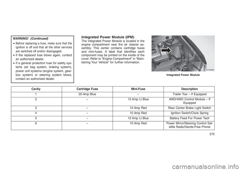
Integrated Power Module (IPM)The Integrated Power Module is located in the
engine compartment near the air cleaner as-
sembly. This center contains cartridge fuses
and mini-fuses. A label that identifies each
component may be printed on the inside of the
cover. Refer to “Engine Compartment” in “Main-
taining Your Vehicle” for further information.
Cavity Cartridge Fuse Mini-Fuse Description
1 20 Amp Blue – Trailer Tow – If Equipped
2 – 15 Amp Lt Blue AWD/4WD Control Module – If
Equipped
3 – 10 Amp Red Rear Center Brake Light Switch
4 – 10 Amp Red Ignition Switch/Clock Spring
5 – 15 Amp Lt Blue Battery Feed For Power Tech
6 – 10 Amp Red Power Mirror/Steering Control Sat-
ellite Radio/Hands-Free Phone
Integrated Power Module
275
Page 280 of 332
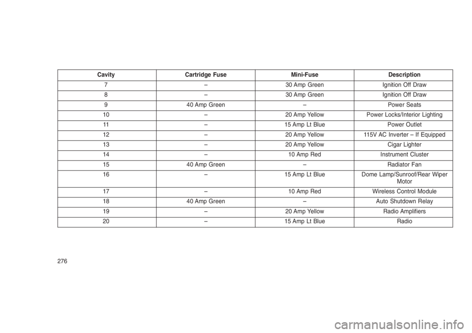
Cavity Cartridge Fuse Mini-Fuse Description
7 – 30 Amp Green Ignition Off Draw
8 – 30 Amp Green Ignition Off Draw
9 40 Amp Green – Power Seats
10 – 20 Amp Yellow Power Locks/Interior Lighting
11 – 15 Amp Lt Blue Power Outlet
12 – 20 Amp Yellow 115V AC Inverter – If Equipped
13 – 20 Amp Yellow Cigar Lighter
14 – 10 Amp Red Instrument Cluster
15 40 Amp Green – Radiator Fan
16 – 15 Amp Lt Blue Dome Lamp/Sunroof/Rear Wiper
Motor
17 – 10 Amp Red Wireless Control Module
18 40 Amp Green – Auto Shutdown Relay
19 – 20 Amp Yellow Radio Amplifiers
20 – 15 Amp Lt Blue Radio
276
Page 283 of 332
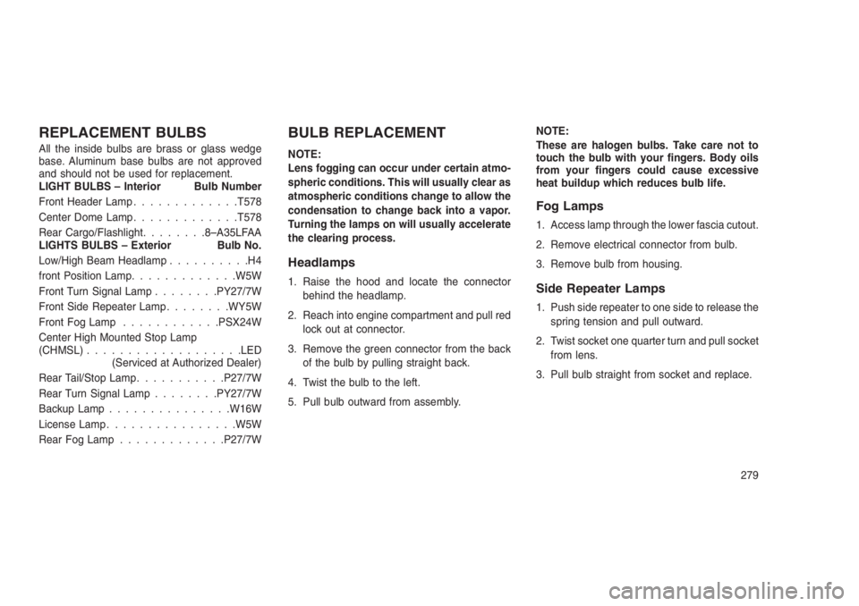
REPLACEMENT BULBS
All the inside bulbs are brass or glass wedge
base. Aluminum base bulbs are not approved
and should not be used for replacement.
LIGHT BULBS – Interior Bulb Number
Front Header Lamp.............T578
Center Dome Lamp.............T578
Rear Cargo/Flashlight........8–A35LFAA
LIGHTS BULBS – Exterior Bulb No.
Low/High Beam Headlamp..........H4
front Position Lamp.............W5W
Front Turn Signal Lamp........PY27/7W
Front Side Repeater Lamp........WY5W
Front Fog Lamp............PSX24W
Center High Mounted Stop Lamp
(CHMSL)...................LED
(Serviced at Authorized Dealer)
Rear Tail/Stop Lamp...........P27/7W
Rear Turn Signal Lamp........PY27/7W
Backup Lamp...............W16W
License Lamp................W5W
Rear Fog Lamp.............P27/7W
BULB REPLACEMENT
NOTE:
Lens fogging can occur under certain atmo-
spheric conditions. This will usually clear as
atmospheric conditions change to allow the
condensation to change back into a vapor.
Turning the lamps on will usually accelerate
the clearing process.
Headlamps
1. Raise the hood and locate the connector
behind the headlamp.
2. Reach into engine compartment and pull red
lock out at connector.
3. Remove the green connector from the back
of the bulb by pulling straight back.
4. Twist the bulb to the left.
5. Pull bulb outward from assembly.NOTE:
These are halogen bulbs. Take care not to
touch the bulb with your fingers. Body oils
from your fingers could cause excessive
heat buildup which reduces bulb life.
Fog Lamps
1. Access lamp through the lower fascia cutout.
2. Remove electrical connector from bulb.
3. Remove bulb from housing.
Side Repeater Lamps
1. Push side repeater to one side to release the
spring tension and pull outward.
2. Twist socket one quarter turn and pull socket
from lens.
3. Pull bulb straight from socket and replace.
279
Page 284 of 332
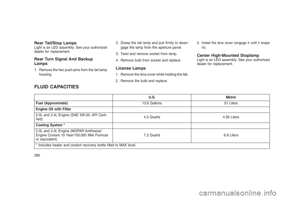
Rear Tail/Stop LampsLight is an LED assembly. See your authorized
dealer for replacement.
Rear Turn Signal And Backup
Lamps
1. Remove the two push-pins from the tail lamp
housing.2. Grasp the tail lamp and pull firmly to disen-
gage the lamp from the aperture panel.
3. Twist and remove socket from lamp.
4. Remove bulb from socket and replace.License Lamps
1. Remove the lens cover while holding the tab.
2. Remove the bulb and replace.3.
Install the lens cover (engage it until it snaps
in).
Center High-Mounted StoplampLight is an LED assembly. See your authorized
dealer for replacement.
FLUID CAPACITIES
U.S. Metric
Fuel (Approximate)13.6 Gallons 51 Liters
Engine Oil with Filter
2.0L and 2.4L Engine (SAE 5W-20, API Certi-
fied)4.5 Quarts 4.26 Liters
Cooling System *
2.0L and 2.4L Engine (MOPAR Antifreeze/
Engine Coolant 10 Year/150,000 Mile Formula
or equivalent)7.2 Quarts 6.8 Liters
* Includes heater and coolant recovery bottle filled to MAX level.
280