warning light JEEP PATRIOT 2019 Owner handbook (in English)
[x] Cancel search | Manufacturer: JEEP, Model Year: 2019, Model line: PATRIOT, Model: JEEP PATRIOT 2019Pages: 332, PDF Size: 1.99 MB
Page 64 of 332
WARNING!(Continued)
•Always make sure that objects cannot fall
into the driver footwell while the vehicle is
moving. Objects can become trapped un-
der the brake pedal and accelerator pedal
causing a loss of vehicle control.
•If required, mounting posts must be prop-
erly installed, if not equipped from the
factory.
Failure to properly follow floor mat installa-
tion or mounting can cause interference with
the brake pedal and accelerator pedal opera-
tion causing loss of control of the vehicle.
Periodic Safety Checks You Should
Make Outside The Vehicle
Tires
Examine tires for excessive tread wear and
uneven wear patterns. Check for stones, nails,
glass, or other objects lodged in the tread or
sidewall. Inspect the tread for cuts and cracks.
Inspect sidewalls for cuts, cracks, and bulges.
Check the wheel nuts for tightness. Check the
tires (including spare) for proper cold inflation
pressure.
Lights
Have someone observe the operation of brake
lights and exterior lights while you work the
controls. Check turn signal and high beam
indicator lights on the instrument panel.Door Latches
Check for proper closing, latching, and locking.
Fluid Leaks
Check area under vehicle after overnight park-
ing for fuel, engine coolant, oil, or other fluid
leaks. Also, if gasoline fumes are detected or if
fuel, power steering fluid (if equipped), or brake
fluid leaks are suspected. The cause should be
located and corrected immediately.
60
Page 69 of 332
MIRRORS
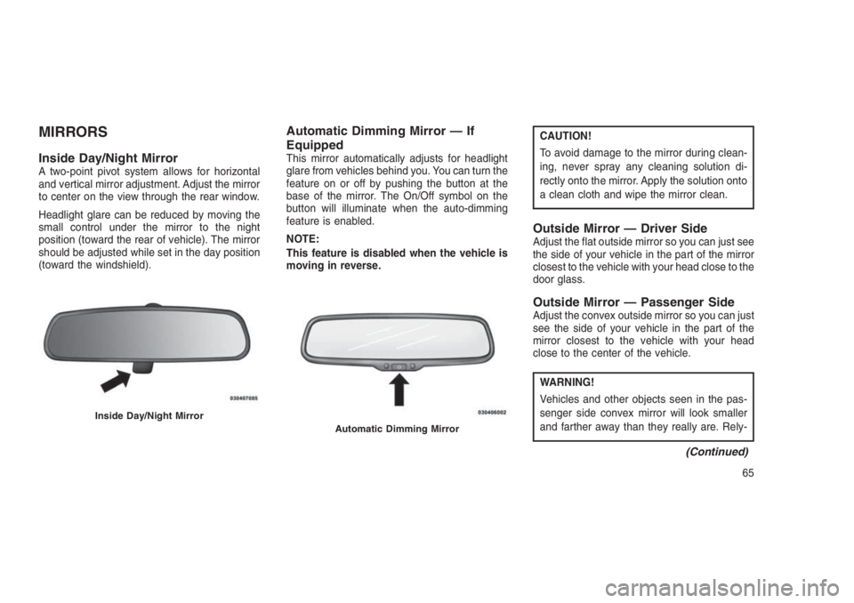
Inside Day/Night MirrorA two-point pivot system allows for horizontal
and vertical mirror adjustment. Adjust the mirror
to center on the view through the rear window.
Headlight glare can be reduced by moving the
small control under the mirror to the night
position (toward the rear of vehicle). The mirror
should be adjusted while set in the day position
(toward the windshield).
Automatic Dimming Mirror — If
Equipped
This mirror automatically adjusts for headlight
glare from vehicles behind you. You can turn the
feature on or off by pushing the button at the
base of the mirror. The On/Off symbol on the
button will illuminate when the auto-dimming
feature is enabled.
NOTE:
This feature is disabled when the vehicle is
moving in reverse.
CAUTION!
To avoid damage to the mirror during clean-
ing, never spray any cleaning solution di-
rectly onto the mirror. Apply the solution onto
a clean cloth and wipe the mirror clean.
Outside Mirror — Driver SideAdjust the flat outside mirror so you can just see
the side of your vehicle in the part of the mirror
closest to the vehicle with your head close to the
door glass.
Outside Mirror — Passenger SideAdjust the convex outside mirror so you can just
see the side of your vehicle in the part of the
mirror closest to the vehicle with your head
close to the center of the vehicle.
WARNING!
Vehicles and other objects seen in the pas-
senger side convex mirror will look smaller
and farther away than they really are. Rely-
(Continued)
Inside Day/Night MirrorAutomatic Dimming Mirror
65
Page 78 of 332
•After the “Ready” prompt and the following
beep, say the name of the language you wish
to switch to (English, Dutch, French, Ger-
man, Italian, or Spanish, if so equipped).
•Continue to follow the system prompts to
complete the language selection.
After selecting one of the languages, all
prompts and voice commands will be in that
language.
Emergency Assistance
If you are in an emergency and the mobile
phone is reachable:
•Pick up the phone and manually dial the
emergency number for your area.
If the phone is not reachable and the Uconnect
Phone is operational, you may reach the emer-
gency number as follows:
•Push the Phone
button to begin.
•After the “Ready” prompt and the following
beep, say “Emergency” and the Uconnect
Phone will instruct the paired mobile phone
to call the emergency number.NOTE:
•The default number is 112. The number
dialed may not be applicable with the
available mobile service and area.
•If supported, this number may be pro-
grammable on some systems. To do this,
push the Phone
button and say
“Setup,” followed by “Emergency.”
•The Uconnect Phone does slightly lower
your chances of successfully making a
phone call as to that for the mobile phone
directly.
WARNING!
To use your Uconnect Phone System in an
emergency, your mobile phone must be:
•Turned on.
•Paired to the Uconnect System.
•Have network coverage.
Breakdown Service — If Equipped
If you need Breakdown service:
1. Push the Phone
button to begin.2. After the “Ready” prompt and the following
beep, say “Breakdown service.”
NOTE:
The Breakdown service number has to be
setup before using. To setup, push the
Phone
button and say “Setup, Break-
down Service” and follow prompts.
Paging
To learn how to page, refer to “Working with
Automated Systems.” Paging works properly
except for pagers of certain companies, which
time out a little too soon to work properly with
the Uconnect Phone.
Voice Mail Calling
To learn how to access your voice mail, refer to
“Working with Automated Systems.”
Working With Automated Systems
This method is used in instances where one
generally has to push numbers on the mobile
phone keypad while navigating through an au-
tomated telephone system.
You can use your Uconnect Phone to access a
voice mail system or an automated service,
such as a paging service or automated cus-
74
Page 93 of 332
WARNING!
•Adjusting a seat while driving may be
dangerous. Moving a seat while driving
could result in loss of control which could
cause a collision and serious injury or
death.
•Seats should be adjusted before fastening
the seat belts and while the vehicle is
parked. Serious injury or death could result
from a poorly adjusted seat belt.
CAUTION!
Do not place any article under a power seat
or impede its ability to move as it may cause
damage to the seat controls. Seat travel may
become limited if movement is stopped by an
obstruction in the seat’s path.
Adjusting The Seat Forward Or Rearward
The seat can be adjusted both forward and
rearward. Push the seat switch forward or rear-
ward. The seat will move in the direction of theswitch. Release the switch when the desired
position has been reached.
Adjusting The Seat Up Or Down
The height of the seats can be adjusted up or
down. Pull upward or push downward on the
seat switch. The seat will move in the direction
of the switch. Release the switch when the
desired position is reached.
Tilting The Seat Up Or Down
The angle of the seat cushion can be adjusted
in four directions. Pull upward or push down-
ward on the front or rear of the seat switch, the
front or rear of the seat cushion will move in the
direction of the switch. Release the switch when
the desired position is reached.
Heated Seats — If EquippedOn some models, the front driver and passen-
ger seats may be equipped with heaters in both
the seat cushions and seatbacks. The controls
for the front heated seats are located on the
center instrument panel area.
You can choose from HI, LO or OFF heat
settings. Amber indicator lights in each switchindicate the level of heat in use. Two indicator
lights will illuminate for HI, one for LO and none
for OFF.
Push the switch once to select HI-
level heating. Push the switch a sec-
ond time to select LO-level heating.
Push the switch a third time to shut
the heating elements OFF.
When the HI-level setting is selected, the heater
will provide a boosted heat level during the
initial stages of operation. Then, the heat output
will drop to the normal HI-level. If the HI-level
setting is selected, the system will automatically
switch to LO-level after approximately 30 min-
utes of continuous operation. At that time, the
display will change from HI to LO, indicating the
change. When the LO-level heating is selected,
the system automatically turns the heater and
the indicator light OFF after approximately 30
minutes of continuous operation.
NOTE:
Once a heat setting is selected, heat will be
felt within two to five minutes.
89
Page 100 of 332

CAUTION!
To prevent possible damage:
•Before closing hood, make sure the hood
prop rod is fully seated into its storage
retaining clips.
•
Do not slam the hood to close it. Use a firm
downward push at the center front edge of the
hood to ensure that both latches engage.
Never drive your vehicle unless the hood is
fully closed, with both latches engaged.
WARNING!
Be sure the hood is fully latched before
driving your vehicle. If the hood is not fully
latched, it could open when the vehicle is in
motion and block your vision. Failure to
follow this warning could result in serious
injury or death.
LIGHTS
Multifunction LeverThe multifunction lever controls the operation of
the headlights, position lights, side marker
lights, turn signals, headlight beam selection,
instrument panel light dimming, interior lights,
the passing lights and fog lights. The lever is
located on the left side of the steering column.Headlights And Parking LightsTurn the end of the multifunction lever to the first
detent to activate parking lights. Turn to the
second detent for headlight operation.
Prop Rod LocationMultifunction Lever
96
Page 106 of 332
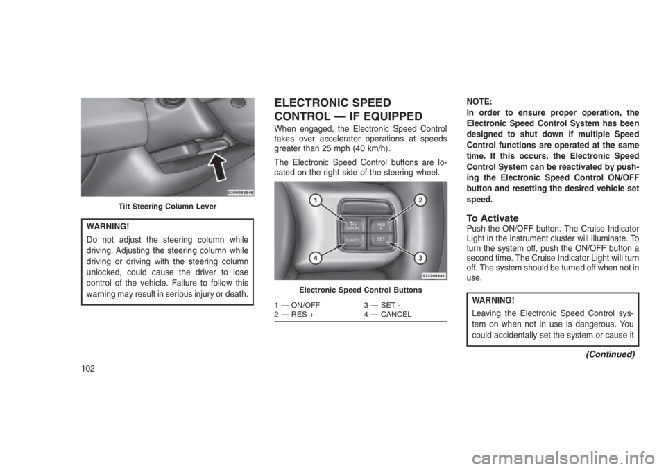
WARNING!
Do not adjust the steering column while
driving. Adjusting the steering column while
driving or driving with the steering column
unlocked, could cause the driver to lose
control of the vehicle. Failure to follow this
warning may result in serious injury or death.
ELECTRONIC SPEED
CONTROL — IF EQUIPPED
When engaged, the Electronic Speed Control
takes over accelerator operations at speeds
greater than 25 mph (40 km/h).
The Electronic Speed Control buttons are lo-
cated on the right side of the steering wheel.NOTE:
In order to ensure proper operation, the
Electronic Speed Control System has been
designed to shut down if multiple Speed
Control functions are operated at the same
time. If this occurs, the Electronic Speed
Control System can be reactivated by push-
ing the Electronic Speed Control ON/OFF
button and resetting the desired vehicle set
speed.
To ActivatePush the ON/OFF button. The Cruise Indicator
Light in the instrument cluster will illuminate. To
turn the system off, push the ON/OFF button a
second time. The Cruise Indicator Light will turn
off. The system should be turned off when not in
use.
WARNING!
Leaving the Electronic Speed Control sys-
tem on when not in use is dangerous. You
could accidentally set the system or cause it
(Continued)
Tilt Steering Column Lever
Electronic Speed Control Buttons
1 — ON/OFF 3 — SET -
2 — RES + 4 — CANCEL
102
Page 108 of 332
U.S. Speed (mph)
•Pushing the SET (-) button once will result in
a 1 mph decrease in set speed. Each subse-
quent tap of the button results in a decrease
of 1 mph.
•If the button is continually pushed, the set
speed will continue to decrease until the
button is released, then the new set speed
will be established.
Metric Speed (km/h)
•Pushing the SET (-) button once will result in
a 1 km/h decrease in set speed. Each sub-
sequent tap of the button results in a de-
crease of 1 km/h.
•If the button is continually pushed, the set
speed will continue to decrease until the
button is released, then the new set speed
will be established.
Manual TransmissionPressing the clutch pedal will disengage the
speed control. A slight increase in engine RPM
before the Electronic Speed Control disen-
gages is normal.Vehicles equipped with manual transmissions
may need to be shifted into a lower gear to climb
hills without speed loss.
To Accelerate For PassingPress the accelerator as you would normally.
When the pedal is released, the vehicle will
return to the set speed.
Using Electronic Speed Control On Hills
The transmission may downshift on hills to
maintain the vehicle set speed.
NOTE:
The Electronic Speed Control system main-
tains speed up and down hills. A slight
speed change on moderate hills is normal.
On steep hills, a greater speed loss or gain may
occur so it may be preferable to drive without
Electronic Speed Control.
WARNING!
Electronic Speed Control can be dangerous
where the system cannot maintain a constant
(Continued)
WARNING!(Continued)
speed. Your vehicle could go too fast for the
conditions, and you could lose control and
have an accident. Do not use Electronic Speed
Control in heavy traffic or on roads that are
winding, icy, snow-covered or slippery.
PARKVIEW REAR BACK UP
CAMERA — IF EQUIPPED
Your vehicle may be equipped with the
ParkView Rear Back Up Camera that allows
you to see an on-screen image of the rear
surroundings of your vehicle whenever the gear
selector is put into REVERSE. The image will
be displayed on the touchscreen along with a
caution note to “check entire surroundings”
across the top of the screen. After five seconds
this note will disappear. The ParkView camera
is located on the rear of the vehicle above the
rear license plate.
When the vehicle is shifted out of REVERSE,
the rear camera mode is exited and the last
selected touchscreen appears again.
104
Page 112 of 332
ELECTRICAL POWER
OUTLETS
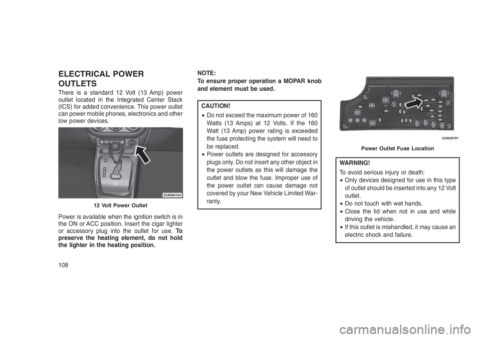
There is a standard 12 Volt (13 Amp) power
outlet located in the Integrated Center Stack
(ICS) for added convenience. This power outlet
can power mobile phones, electronics and other
low power devices.
Power is available when the ignition switch is in
the ON or ACC position. Insert the cigar lighter
or accessory plug into the outlet for use.To
preserve the heating element, do not hold
the lighter in the heating position.NOTE:
To ensure proper operation a MOPAR knob
and element must be used.
CAUTION!
•Do not exceed the maximum power of 160
Watts (13 Amps) at 12 Volts. If the 160
Watt (13 Amp) power rating is exceeded
the fuse protecting the system will need to
be replaced.
•Power outlets are designed for accessory
plugs only. Do not insert any other object in
the power outlets as this will damage the
outlet and blow the fuse. Improper use of
the power outlet can cause damage not
covered by your New Vehicle Limited War-
ranty.
WARNING!
To avoid serious injury or death:
•Only devices designed for use in this type
of outlet should be inserted into any 12 Volt
outlet.
•Do not touch with wet hands.
•Close the lid when not in use and while
driving the vehicle.
•If this outlet is mishandled, it may cause an
electric shock and failure.
12 Volt Power Outlet
Power Outlet Fuse Location
108
Page 115 of 332
CONSOLE FEATURES
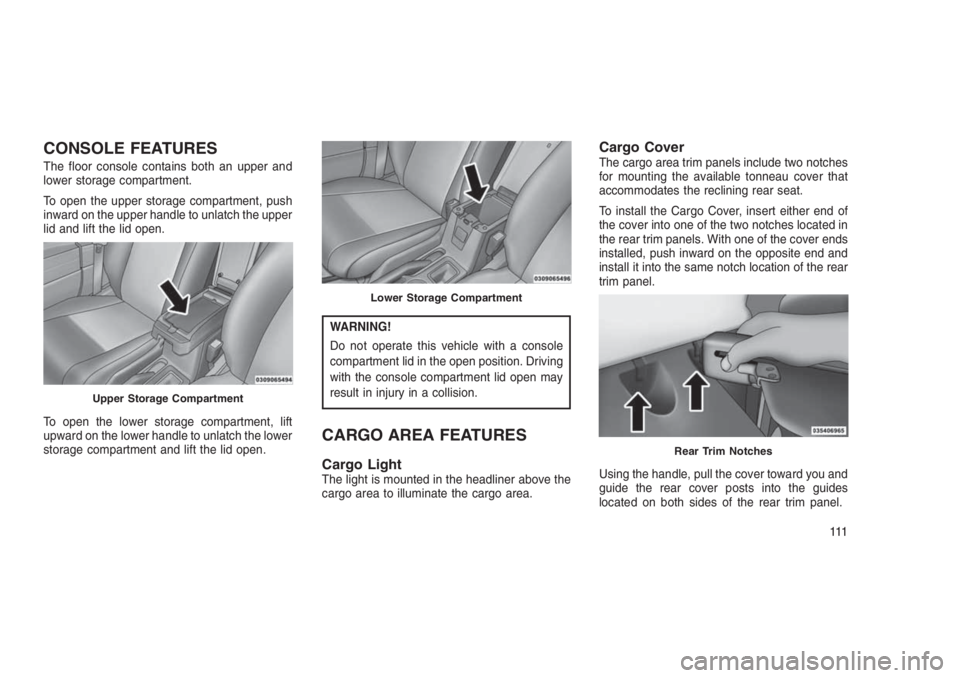
The floor console contains both an upper and
lower storage compartment.
To open the upper storage compartment, push
inward on the upper handle to unlatch the upper
lid and lift the lid open.
To open the lower storage compartment, lift
upward on the lower handle to unlatch the lower
storage compartment and lift the lid open.
WARNING!
Do not operate this vehicle with a console
compartment lid in the open position. Driving
with the console compartment lid open may
result in injury in a collision.
CARGO AREA FEATURES
Cargo LightThe light is mounted in the headliner above the
cargo area to illuminate the cargo area.
Cargo CoverThe cargo area trim panels include two notches
for mounting the available tonneau cover that
accommodates the reclining rear seat.
To install the Cargo Cover, insert either end of
the cover into one of the two notches located in
the rear trim panels. With one of the cover ends
installed, push inward on the opposite end and
install it into the same notch location of the rear
trim panel.
Using the handle, pull the cover toward you and
guide the rear cover posts into the guides
located on both sides of the rear trim panel.
Upper Storage Compartment
Lower Storage Compartment
Rear Trim Notches
111
Page 121 of 332
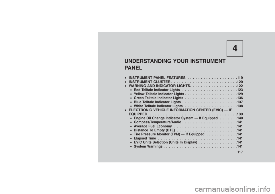
4
UNDERSTANDING YOUR INSTRUMENT
PANEL
•INSTRUMENT PANEL FEATURES...................119
•INSTRUMENT CLUSTER . . . . . . . . . . . . . . . . . . . . . . . . .120
•WARNING AND INDICATOR LIGHTS. . .. . . . . . . . . . . . . . .122
•Red Telltale Indicator Lights.....................123
•Yellow Telltale Indicator Lights....................129
•Green Telltale Indicator Lights....................136
•Blue Telltale Indicator Lights.....................137
•White Telltale Indicator Lights....................138
•ELECTRONIC VEHICLE INFORMATION CENTER (EVIC) — IF
EQUIPPED . . . . . . . ..........................139
•Engine Oil Change Indicator System — If Equipped.......140
•Compass/Temperature/Audio.....................141
•Average Fuel Economy........................141
•Distance To Empty (DTE).......................141
•Tire Pressure Monitor (TPM) — If Equipped............141
•Elapsed Time..............................141
•EVIC Units Selection (Units In Display)...............141
•System Warnings............................141
11 7