battery JEEP PATRIOT 2020 Owner handbook (in English)
[x] Cancel search | Manufacturer: JEEP, Model Year: 2020, Model line: PATRIOT, Model: JEEP PATRIOT 2020Pages: 332, PDF Size: 1.99 MB
Page 143 of 332
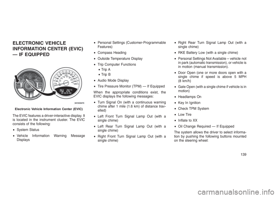
ELECTRONIC VEHICLE
INFORMATION CENTER (EVIC)
— IF EQUIPPED
The EVIC features a driver-interactive display. It
is located in the instrument cluster. The EVIC
consists of the following:
•System Status
•Vehicle Information Warning Message
Displays•Personal Settings (Customer-Programmable
Features)
•Compass Heading
•Outside Temperature Display
•Trip Computer Functions
•Trip A
•Trip B
•Audio Mode Display
•Tire Pressure Monitor (TPM) — If Equipped
When the appropriate conditions exist, the
EVIC displays the following messages:
•Turn Signal On (with a continuous warning
chime after 1 mile (1.6 km) of distance trav-
elled)
•Left Front Turn Signal Lamp Out (with a
single chime)
•Left Rear Turn Signal Lamp Out (with a
single chime)
•Right Front Turn Signal Lamp Out (with a
single chime)•Right Rear Turn Signal Lamp Out (with a
single chime)
•RKE Battery Low (with a single chime)
•Personal Settings Not Available – vehicle not
in park (automatic transmission), or vehicle is
in motion (manual transmission).
•Door Open (one or more doors open with a
single chime if speed is above 5 MPH
(8 km/h)
•Gate Open (with a single chime if vehicle is in
motion)
•Headlamps On
•Key In Ignition
•Check TPM System
•Low Tire
•Inflate to XX
•Oil Change Required — If Equipped
The system allows the driver to select informa-
tion by pushing the following buttons mounted
on the steering wheel:
Electronic Vehicle Information Center (EVIC)
139
Page 147 of 332
Illuminated Approach
When this feature is selected, the headlights will
activate and remain on for up to 90 seconds
when the doors are unlocked using the RKE
Key Fob. Push and hold theRIGHT
arrow
button when in this display until “OFF,” “30 sec,”
“60 sec,” or “90 sec.” appears to make your
selection.
Hill Start Assist (HSA) — If Equipped
When “On” is selected, the HSA system is
active. Refer to “Electronic Brake Control Sys-
tem” in “Starting And Operating” for system
function and operating information. To make
your selection, push and release theRIGHT
arrow button until “On” or “Off” appears.
Display Units In
The EVIC, odometer, and Uconnect GPS sys-
tem units can be changed between US and
Metric.
Push and hold theRIGHT
arrow button
when in this display until “US” or “METRIC”
appears to make your selection.
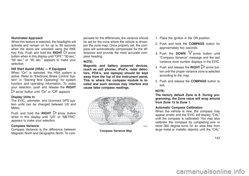
Compass Variance
Compass Variance is the difference between
Magnetic North and Geographic North. To com-pensate for the differences, the variance should
be set for the zone where the vehicle is driven,
per the zone map. Once properly set, the com-
pass will automatically compensate for the dif-
ferences and provide the most accurate com-
pass heading.
NOTE:
Magnetic and battery powered devices,
(such as cell phones, iPod’s, radar detec-
tors, PDA’s, and laptops) should be kept
away from the top of the instrument panel.
This is where the compass module is lo-
cated and such devices may interfere and
cause false compass readings.1. Place the ignition in the ON position.
2. Push and hold theCOMPASSbutton for
approximately two seconds.
3. Push theDOWN
arrow button until
“Compass Variance” message and the last
variance zone number displays in the EVIC.
4. Push and release theRIGHT
arrow but-
ton until the proper variance zone is selected
according to the map.
5. Push and release theCOMPASSbutton to
exit.
NOTE:
The factory default Zone is 8. During pro-
gramming, the Zone value will wrap around
from Zone 15 to Zone 1.
Automatic Compass Calibration
When the vehicle is new, the compass may
appear erratic and the EVIC will display “CAL”
until the compass is calibrated. You may also
calibrate the compass by completing one or
more 360 degree turns (in an area free from
large metal or metallic objects) until the “CAL”
Compass Variance Map
143
Page 150 of 332
Once the audio device is connected and syn-
chronized to the vehicle’s iPod/USB/MP3 con-
trol system (iPod or external USB device may
take a few minutes to connect), the audio
device starts charging and is ready for use by
pushing radio switches, as described below.
NOTE:
If the audio device battery is completely
discharged, it may not communicate with
the iPod/USB/MP3 control system until a
minimum charge is attained. Leaving the
audio device connected to the iPod/USB/MP3 control system may charge it to the
required level.
Using This FeatureBy using an external USB device to connect to
the USB port:
•The audio device can be played on the
vehicle’s sound system, providing metadata
(artist, track title, album, etc.) information on
the radio display.
•The audio device can be controlled using the
radio buttons to Play, Browse, and List the
iPod contents.
•The audio device battery charges when
plugged into the USB/AUX connector (if sup-
ported by the specific audio device).
Controlling The iPod Or External
USB Device Using Radio Buttons
To enter the iPod/USB/MP3 control mode and
access a connected audio device, either push
the “AUX” button on the radio faceplate or push
the VR button and say"USB"or"Switch to
USB."Once in the iPod/USB/MP3 controlmode, audio tracks (if available from audio
device) start playing over the vehicle’s audio
system.
Play ModeWhen switched to iPod/USB/MP3 control mode,
the iPod or external USB device automatically
starts Play mode. In Play mode, the following
buttons on the radio faceplate may be used to
control the iPod or external USB device and
display data:
•Use theTUNEcontrol knob to select the next
or previous track.
•Turning it clockwise (forward) by one
click, while playing a track, skips to the
next track or push the VR button and say
"Next Track."
•Turning it counterclockwise (backward)
by one click, will jump to the previous
track in the list or push the VR button and
say"Previous Track."
•Jump backward in the current track by push-
ing and holding the <
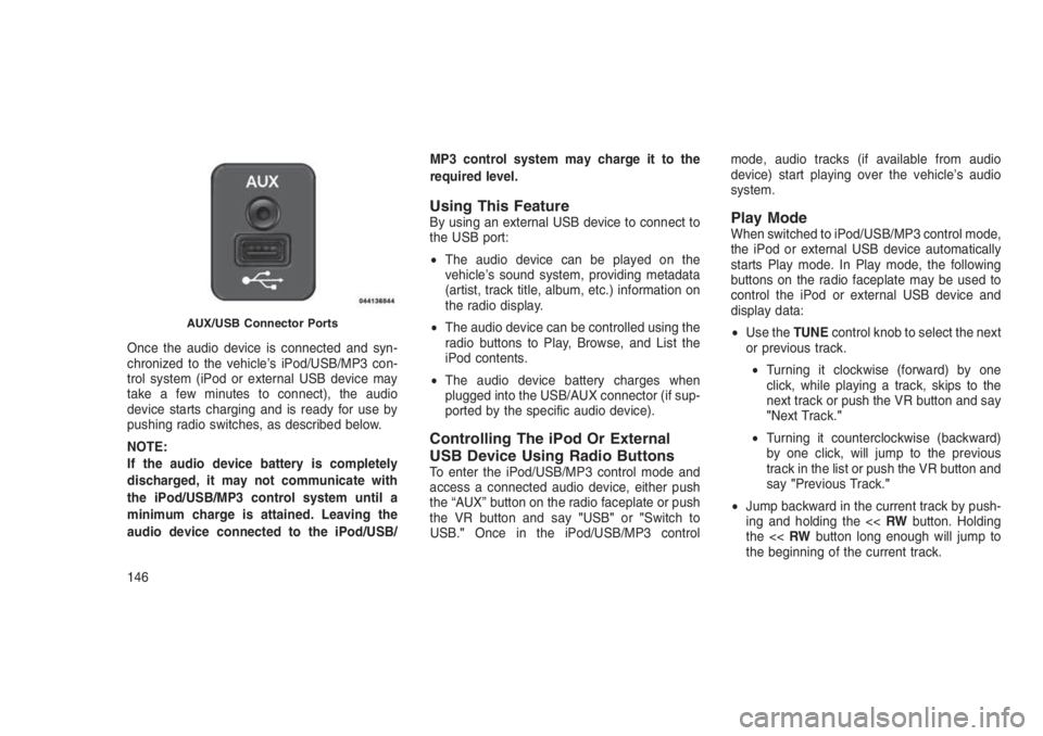
AUX/USB Connector Ports
146
Page 231 of 332
HAZARD WARNING FLASHERS
The Hazard Warning flasher switch is located
on the instrument panel below the climate
controls.
Push the switch to turn on the Hazard
Warning flasher. When the switch is
activated, all directional turn signals
will flash on and off to warn oncoming traffic of
an emergency. Push the switch a second time
to turn off the Hazard Warning flashers.
This is an emergency warning system and it
should not be used when the vehicle is in
motion. Use it when your vehicle is disabled and
it is creating a safety hazard for other motorists.
When you must leave the vehicle to seek assis-
tance, the Hazard Warning flashers will con-
tinue to operate even though the ignition is
placed in the OFF position.
NOTE:
With extended use the Hazard Warning
flashers may wear down your battery.
IF YOUR ENGINE OVERHEATS
In any of the following situations, you can
reduce the potential for overheating by taking
the appropriate action.
•On the highways — slow down.
•In city traffic — while stopped, place the
transmission in NEUTRAL, but do not in-
crease engine idle speed.
NOTE:
There are steps that you can take to slow
down an impending overheat condition:
•If your air conditioner (A/C) is on, turn it
off. The A/C system adds heat to the
engine cooling system and turning the
A/C off can help remove this heat.
•You can also turn the temperature control
to maximum heat, the mode control to
floor and the blower control to high. This
allows the heater core to act as a supple-
ment to the radiator and aids in removing
heat from the engine cooling system.CAUTION!
Driving with a hot cooling system could dam-
age your vehicle. If the pointer rises to the
H(red) mark, the instrument cluster will
sound a chime. When safe, pull over and
stop the vehicle with the engine at idle. Turn
off the air conditioning and wait until the
pointer drops back into the normal range. If
the pointer remains on theH(red) mark for
more than a minute, turn the engine off
immediately and call for service.
WARNING!
You or others can be badly burned by hot
engine coolant (antifreeze) or steam from
your radiator. If you see or hear steam com-
ing from under the hood, do not open the
hood until the radiator has had time to cool.
Never try to open a cooling system pressure
cap when the radiator or coolant bottle is hot.
227
Page 245 of 332
JUMP-STARTING
PROCEDURES
If your vehicle has a discharged battery it can be
jump-started using a set of jumper cables and a
battery in another vehicle or by using a portable
battery booster pack. Jump-starting can be dan-
gerous if done improperly so please follow the
procedures in this section carefully.
NOTE:
When using a portable battery booster pack
follow the manufacturer’s operating instruc-
tions and precautions.
CAUTION!
Do not use a portable battery booster pack or
any other booster source with a system
voltage greater than 12 Volts or damage to
the battery, starter motor, alternator or elec-
trical system may occur.
WARNING!
Do not attempt jump-starting if the battery is
frozen. It could rupture or explode and cause
personal injury.
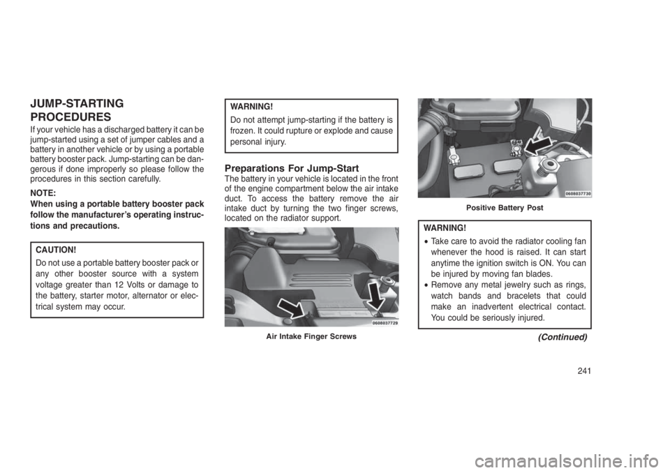
Preparations For Jump-StartThe battery in your vehicle is located in the front
of the engine compartment below the air intake
duct. To access the battery remove the air
intake duct by turning the two finger screws,
located on the radiator support.
WARNING!
•Take care to avoid the radiator cooling fan
whenever the hood is raised. It can start
anytime the ignition switch is ON. You can
be injured by moving fan blades.
•Remove any metal jewelry such as rings,
watch bands and bracelets that could
make an inadvertent electrical contact.
You could be seriously injured.
(Continued)Air Intake Finger Screws
Positive Battery Post
241
Page 246 of 332
WARNING!(Continued)
•Batteries contain sulfuric acid that can
burn your skin or eyes and generate hy-
drogen gas which is flammable and explo-
sive. Keep open flames or sparks away
from the battery.
1. Set the parking brake, shift the automatic
transmission into PARK (manual transmis-
sion to NEUTRAL) and turn the ignition to
LOCK.
2. Turn off the heater, radio, and all unneces-
sary electrical accessories.
3. If using another vehicle to jump-start the
battery, park the vehicle within the jumper
cables reach, set the parking brake and
make sure the ignition is OFF.
WARNING!
Do not allow vehicles to touch each other as
this could establish a ground connection and
personal injury could result.
Jump-Starting Procedure
WARNING!
Failure to follow this jump-starting procedure
could result in personal injury or property
damage due to battery explosion.
CAUTION!
Failure to follow these procedures could re-
sult in damage to the charging system of the
booster vehicle or the discharged vehicle.
NOTE:
Remove Air Intake before proceeding with
this Jump-Starting procedure.Connecting The Jumper Cables
1. Connect the positive(+)end of the jumper
cable to the positive(+)post of the dis-
charged vehicle.
2. Connect the opposite end of the positive(+)
jumper cable to the positive(+)post of the
booster battery.
3. Connect the negative end(-)of the jumper
cable to the negative(-)post of the booster
battery.
4. Connect the opposite end of the negative(-)
jumper cable to a good engine ground (ex-
posed metal part of the discharged vehicle’s
engine) away from the battery and the fuel
injection system.
WARNING!
Do not connect the jumper cable to the
negative(-)post of the discharged battery.
The resulting electrical spark could cause
(Continued)
242
Page 247 of 332
WARNING!(Continued)
the battery to explode and could result in
personal injury. Only use the specific ground
point, do not use any other exposed metal
parts.
5. Start the engine in the vehicle that has the
booster battery, let the engine idle a few
minutes, and then start the engine in the
vehicle with the discharged battery.
6. Once the engine is started, remove the
jumper cables in the reverse sequence:
Disconnecting The Jumper Cables
1. Disconnect the negative(-)end of the
jumper cable from the engine ground of the
vehicle with the discharged battery.
2. Disconnect the opposite end of the negative
(-)jumper cable from the negative(-)post of
the booster battery.3. Disconnect the positive(+)end of the jumper
cable from the positive(+)post of the
booster battery.
4. Disconnect the opposite end of the positive
(+)jumper cable from the positive(+)post of
the vehicle with the discharged battery.
5. Reinstall the air intake duct.
If frequent jump-starting is required to start your
vehicle you should have the battery and charg-
ing system inspected at your authorized dealer.
CAUTION!
Accessories plugged into the vehicle power
outlets draw power from the vehicle’s bat-
tery, even when not in use (i.e., cellular
devices, etc.). Eventually, if plugged in long
enough without engine operation, the vehi-
cle’s battery will discharge sufficiently to de-
grade battery life and/or prevent the engine
from starting.
FREEING A STUCK VEHICLE
If your vehicle becomes stuck in mud, sand or
snow, it can often be moved using a rocking
motion. Turn the steering wheel right and left to
clear the area around the front wheels. Then
shift back and forth between DRIVE and RE-
VERSE (with automatic transmission) or 2nd
gear and REVERSE (with manual transmis-
sion), while gently pressing the accelerator. Use
the least amount of accelerator pedal pressure
that will maintain the rocking motion, without
spinning the wheels, or racing the engine.
CAUTION!
Racing the engine or spinning the wheels
may lead to transmission overheating and
failure. Allow the engine to idle with the
transmission in NEUTRAL for at least one
minute after every five rocking-motion
cycles. This will minimize overheating and
reduce the risk of clutch or transmission
failure during prolonged efforts to free a
stuck vehicle.
243
Page 252 of 332
With Ignition Key
Automatic Transmission
•Front Wheel Drive (FWD) vehicles can be
towed with the front wheels elevated, or on a
flatbed truck (all four wheelsOFFthe
ground).
•Four-Wheel Drive (4WD) vehicles can be
towed on a flatbed truck (all four wheelsOFF
the ground).
If the transmission is operable, Front Wheel
Drive (FWD) and Four Wheel Drive (4WD)
vehicles, with the 6-speed automatic transmis-
sion only (NOTthe Continuously Variable auto-
matic transmission [CVT]), may be flat towed
(with all four wheels on the ground) under the
following conditions:
•The transmission must be in NEUTRAL.
•The key must be in the ACC or ON/RUN
position.
•The towing speed must not exceed 25 mph
(40 km/h).
•The towing distance must not exceed 15
miles (24 km).Front Wheel Drive (FWD) models (with 6-speed
automaticonly) may also be towed (under the
same limitations shown above) with the rear
wheels elevated.
CAUTION!
DO NOT flat tow any vehicle equipped with a
CVT automatic transmission. Damage to the
drivetrain will result. If these vehicles require
towing, make sure all drive wheels are OFF
the ground.
Towing this vehicle in violation of the above
requirements can cause severe transmission
and/or transfer case damage. Damage from
improper towing is not covered under the
New Vehicle Limited Warranty..
If the vehicle’s battery is discharged, refer to
“Gear Selector Override” in this section for
instructions on shifting the automatic transmis-
sion out of PARK for towing.Manual Transmission
•Front Wheel Drive (FWD) or Four-Wheel
Drive (4WD) vehicles can be flat towed (all
four wheels on the ground) with the transmis-
sion in NEUTRAL and the key in the ACC or
ON/RUN position.
•FWD vehicles can be towed with the front
wheels elevated.
•FWD or 4WD vehicles can be towed on a
flatbed truck (all wheelsOFFthe ground).
CAUTION!
•DO NOTflat tow any disabled vehicle if
condition is related to the clutch, transmis-
sion or driveline. Additional damage to the
drivetrain could result.
•
Towing this vehicle in violation of the above
requirements can cause severe engine,
transmission, or drivetrain damage. Damage
from improper towing is not covered under
the New Vehicle Limited Warranty.
248
Page 255 of 332
7
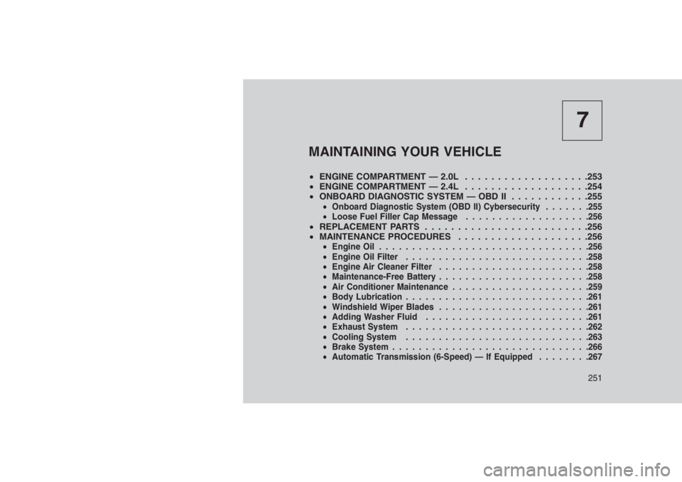
MAINTAINING YOUR VEHICLE
•ENGINE COMPARTMENT — 2.0L . . . . . . . . . . . . .. . . . . .253
•ENGINE COMPARTMENT — 2.4L . . . . . . . . . . . . .. . . . . .254
•ONBOARD DIAGNOSTIC SYSTEM — OBD II . . ..........255
•Onboard Diagnostic System (OBD II) Cybersecurity.......255
•Loose Fuel Filler Cap Message...................256
•REPLACEMENT PARTS . . . . . . . . . . . . . . . . . . . . . . . . .256
•MAINTENANCE PROCEDURES . . . . . . . . . . . . . . ......256
•Engine Oil................................256
•Engine Oil Filter............................258
•Engine Air Cleaner Filter.......................258
•Maintenance-Free Battery.......................258
•Air Conditioner Maintenance.....................259
•Body Lubrication............................261
•Windshield Wiper Blades.......................261
•Adding Washer Fluid.........................261
•Exhaust System............................262
•Cooling System............................263
•Brake System..............................266
•Automatic Transmission (6-Speed) — If Equipped........267
251
Page 262 of 332
Synthetic Engine Oils
There are a number of engine oils being pro-
moted as either synthetic or semi-synthetic. If
you chose to use such a product, use only those
oils that are approved to FCA MS-6395 or FCA
Material Standard 9.55535-CR1. Follow the
maintenance schedule that describes your driv-
ing type.
Materials Added To Engine Oil
The manufacturer strongly recommends
against the addition of any additives (other than
leak detection dyes) to the engine oil. Engine oil
is an engineered product and its performance
may be impaired by supplemental additives.
Disposing Of Used Engine Oil And Oil
Filters
Care should be taken in disposing of used
engine oil and oil filters from your vehicle. Used
oil and oil filters, indiscriminately discarded, can
present a problem to the environment. Contact
your authorized dealer, service station or gov-
ernmental agency for advice on how and where
used oil and oil filters can be safely discarded in
your area.Engine Oil FilterThe engine oil filter should be replaced with a
new filter at every engine oil change.
Engine Oil Filter Selection
This manufacturer’s engines have a full-flow
type oil filter. Use a filter of this type for replace-
ment. The quality of replacement filters varies
considerably. Only high quality filters should be
used to assure most efficient service. MOPAR
engine oil filters are a high quality oil filter and
are recommended.
Engine Air Cleaner FilterRefer to the “Maintenance Schedule” in the
“Maintenance Schedules” section for the proper
maintenance intervals.
WARNING!
The air induction system (air cleaner, hoses,
etc.) can provide a measure of protection in
the case of engine backfire. Do not remove
the air induction system (air cleaner, hoses,
etc.) unless such removal is necessary for
(Continued)
WARNING!(Continued)
repair or maintenance. Make sure that no
one is near the engine compartment before
starting the vehicle with the air induction
system (air cleaner, hoses, etc.) removed.
Failure to do so can result in serious per-
sonal injury.
Engine Air Cleaner Filter Selection
The quality of replacement engine air cleaner
filters varies considerably. Only high quality
filters should be used to assure most efficient
service. MOPAR engine air cleaner filters are a
high quality filter and are recommended.
Maintenance-Free BatteryYour vehicle is equipped with a maintenance-
free battery. You will never have to add water,
nor is periodic maintenance required.
258