heating JEEP PATRIOT 2020 Owner handbook (in English)
[x] Cancel search | Manufacturer: JEEP, Model Year: 2020, Model line: PATRIOT, Model: JEEP PATRIOT 2020Pages: 332, PDF Size: 1.99 MB
Page 93 of 332
WARNING!
•Adjusting a seat while driving may be
dangerous. Moving a seat while driving
could result in loss of control which could
cause a collision and serious injury or
death.
•Seats should be adjusted before fastening
the seat belts and while the vehicle is
parked. Serious injury or death could result
from a poorly adjusted seat belt.
CAUTION!
Do not place any article under a power seat
or impede its ability to move as it may cause
damage to the seat controls. Seat travel may
become limited if movement is stopped by an
obstruction in the seat’s path.
Adjusting The Seat Forward Or Rearward
The seat can be adjusted both forward and
rearward. Push the seat switch forward or rear-
ward. The seat will move in the direction of theswitch. Release the switch when the desired
position has been reached.
Adjusting The Seat Up Or Down
The height of the seats can be adjusted up or
down. Pull upward or push downward on the
seat switch. The seat will move in the direction
of the switch. Release the switch when the
desired position is reached.
Tilting The Seat Up Or Down
The angle of the seat cushion can be adjusted
in four directions. Pull upward or push down-
ward on the front or rear of the seat switch, the
front or rear of the seat cushion will move in the
direction of the switch. Release the switch when
the desired position is reached.
Heated Seats — If EquippedOn some models, the front driver and passen-
ger seats may be equipped with heaters in both
the seat cushions and seatbacks. The controls
for the front heated seats are located on the
center instrument panel area.
You can choose from HI, LO or OFF heat
settings. Amber indicator lights in each switchindicate the level of heat in use. Two indicator
lights will illuminate for HI, one for LO and none
for OFF.
Push the switch once to select HI-
level heating. Push the switch a sec-
ond time to select LO-level heating.
Push the switch a third time to shut
the heating elements OFF.
When the HI-level setting is selected, the heater
will provide a boosted heat level during the
initial stages of operation. Then, the heat output
will drop to the normal HI-level. If the HI-level
setting is selected, the system will automatically
switch to LO-level after approximately 30 min-
utes of continuous operation. At that time, the
display will change from HI to LO, indicating the
change. When the LO-level heating is selected,
the system automatically turns the heater and
the indicator light OFF after approximately 30
minutes of continuous operation.
NOTE:
Once a heat setting is selected, heat will be
felt within two to five minutes.
89
Page 112 of 332
ELECTRICAL POWER
OUTLETS
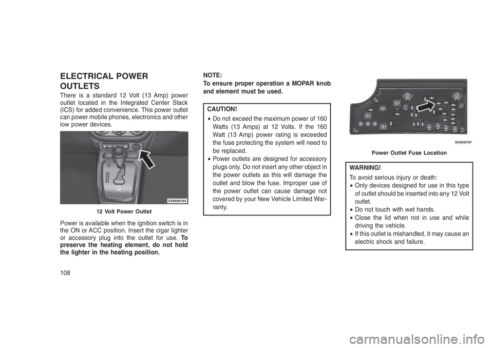
There is a standard 12 Volt (13 Amp) power
outlet located in the Integrated Center Stack
(ICS) for added convenience. This power outlet
can power mobile phones, electronics and other
low power devices.
Power is available when the ignition switch is in
the ON or ACC position. Insert the cigar lighter
or accessory plug into the outlet for use.To
preserve the heating element, do not hold
the lighter in the heating position.NOTE:
To ensure proper operation a MOPAR knob
and element must be used.
CAUTION!
•Do not exceed the maximum power of 160
Watts (13 Amps) at 12 Volts. If the 160
Watt (13 Amp) power rating is exceeded
the fuse protecting the system will need to
be replaced.
•Power outlets are designed for accessory
plugs only. Do not insert any other object in
the power outlets as this will damage the
outlet and blow the fuse. Improper use of
the power outlet can cause damage not
covered by your New Vehicle Limited War-
ranty.
WARNING!
To avoid serious injury or death:
•Only devices designed for use in this type
of outlet should be inserted into any 12 Volt
outlet.
•Do not touch with wet hands.
•Close the lid when not in use and while
driving the vehicle.
•If this outlet is mishandled, it may cause an
electric shock and failure.
12 Volt Power Outlet
Power Outlet Fuse Location
108
Page 118 of 332
Rotate the center portion of the
lever past the first detent to acti-
vate the rear washer. The washer
pump and the wiper will continue to
operate as long as the switch is
held (for a maximum of 10 seconds). Upon
release, the wiper will continue to cycle two
times before returning to the set position.
If the rear wiper is operating when the ignition is
turned OFF, the wiper will automatically return
to the “park” position if power accessory delay is
active. Power accessory delay can be cancelled
by opening the door, if this happens the rear
wiper will stop at its current position and will not
go to “park”.
Rear Window Defroster
The rear window defroster button is
located on the climate controls mode
control knob. Push the button to turn
on the rear window defroster and the
heated outside mirrors (if equipped). An indica-
tor in the button will illuminate when the rear
window defroster is on. The rear window de-
froster automatically turns off after approxi-mately 10 minutes. For an additional five min-
utes of operation, push the button a second
time.
NOTE:
To prevent excessive battery drain, use the
rear window defroster only when the engine
is operating.
CAUTION!
Failure to follow these cautions can cause
damage to the heating elements:
•Use care when washing the inside of the
rear window. Do not use abrasive window
cleaners on the interior surface of the
window. Use a soft cloth and a mild wash-
ing solution, wiping parallel to the heating
elements. Labels can be peeled off after
soaking with warm water.
•Do not use scrapers, sharp instruments, or
abrasive window cleaners on the interior
surface of the window.
•Keep all objects a safe distance from the
window.
ROOF LUGGAGE RACK — IF
EQUIPPED
The crossbars and siderails are designed to
carry the cargo on vehicles equipped with a
luggage rack. The load must not exceed 150 lbs
(68 kg), and should be uniformly distributed
over the luggage rack crossbars.
NOTE:
If not equipped with crossbars, your autho-
rized dealer can order and install MOPAR
crossbars built specifically for this roof rack
system.
Distribute cargo weight evenly on the luggage
rack crossbars. The luggage rack does not
increase the total load carrying capacity of the
vehicle. Be sure the total load of cargo inside
the vehicle plus that on the external rack does
not exceed the maximum vehicle load capacity.
The crossbars must also be secured in one of
the seven detent positions marked with an
arrow on the siderails to prevent movement. To
move the crossbars, loosen the thumb screws
located at the upper edge of each crossbar
approximately eight turns, then move the cross-
11 4
Page 122 of 332
•Personal Settings (Customer-Programmable Features).......142•CYBERSECURITY . . . . . . . . . . . . . . . . . . . . . .. . . . . . . . .144
•SOUND SYSTEMS . . . . . .. . . . . . . . . . . . . . . . . . . . . . . .145
•iPod/USB/MP3 CONTROL — IF EQUIPPED . . . . . . . . . . . . . . .145
•Connecting The iPod Or External USB Device.............145
•Using This Feature.............................146
•Controlling The iPod Or External USB Device Using Radio
Buttons....................................146
•Play Mode..................................146
•List Or Browse Mode............................147
•Bluetooth Streaming Audio (BTSA)...................148
•NAVIGATION SYSTEM — IF EQUIPPED . . . . . . . . . . . . .. . . .149
•STEERING WHEEL AUDIO CONTROLS.................149
•Radio Operation...............................149
•CD Player...................................149
•CD/DVD DISC MAINTENANCE . . . . . . . . . . . . . . . ........150
•RADIO OPERATION AND MOBILE DEVICES . . . . . . . . ......150
•CLIMATE CONTROLS . . . . . . . . . . . . . . . .............150
•Manual Heating And Air Conditioning..................150
•Automatic Temperature Control (ATC) — If Equipped........153
•Operating Tips...............................157
11 8
Page 130 of 332
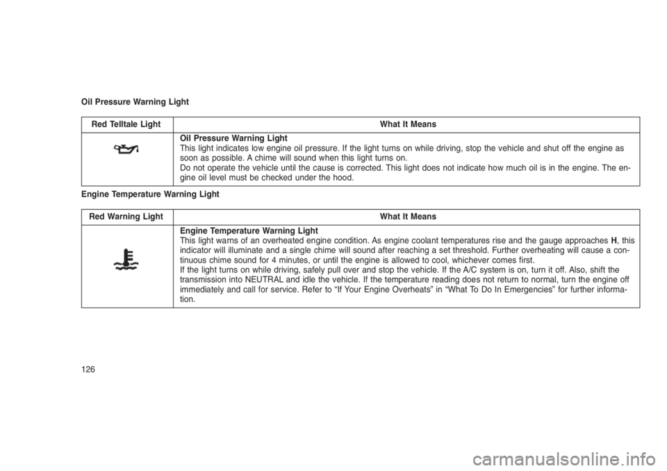
Oil Pressure Warning Light
Red Telltale Light What It Means
Oil Pressure Warning Light
This light indicates low engine oil pressure. If the light turns on while driving, stop the vehicle and shut off the engine as
soon as possible. A chime will sound when this light turns on.
Do not operate the vehicle until the cause is corrected. This light does not indicate how much oil is in the engine. The en-
gine oil level must be checked under the hood.
Engine Temperature Warning Light
Red Warning Light What It Means
Engine Temperature Warning Light
This light warns of an overheated engine condition. As engine coolant temperatures rise and the gauge approachesH, this
indicator will illuminate and a single chime will sound after reaching a set threshold. Further overheating will cause a con-
tinuous chime sound for 4 minutes, or until the engine is allowed to cool, whichever comes first.
If the light turns on while driving, safely pull over and stop the vehicle. If the A/C system is on, turn it off. Also, shift the
transmission into NEUTRAL and idle the vehicle. If the temperature reading does not return to normal, turn the engine off
immediately and call for service. Refer to “If Your Engine Overheats” in “What To Do In Emergencies” for further informa-
tion.
126
Page 154 of 332
If you push the switch up or down twice, it plays
the second track; three times, it will play the
third, etc.
The center button on the left side rocker switch
has no function for a single-disc CD player.
However, when a multiple-disc CD player is
equipped on the vehicle, the center button will
select the next available CD in the player.
CD/DVD DISC MAINTENANCE
To keep a CD/DVD in good condition, take the
following precautions:
1. Handle the disc by its edge; avoid touching
the surface.
2. If the disc is stained, clean the surface with a
soft cloth, wiping from center to edge.
3. Do not apply paper or tape to the disc; avoid
scratching the disc.
4. Do not use solvents such as benzene, thin-
ner, cleaners, or anti-static sprays.
5. Store the disc in its case after playing.
6. Do not expose the disc to direct sunlight.7. Do not store the disc where temperatures
may become too high.
NOTE:
If you experience difficulty in playing a par-
ticular disc, it may be damaged (e.g.,
scratched, reflective coating removed, a
hair, moisture or dew on the disc) oversized,
or have protection encoding. Try a known
good disc before considering disc player
service.
RADIO OPERATION AND
MOBILE DEVICES
Under certain conditions, an “on” mobile device
in your vehicle can cause erratic or noisy per-
formance from your radio. This condition may
be lessened or eliminated by relocating the
mobile device antenna. This condition is not
harmful to the radio. If your radio performance
does not satisfactorily “clear” by the reposition-
ing of the antenna, it is recommended that the
radio volume be turned down or off during
mobile device operation when not using
Uconnect (if equipped).
CLIMATE CONTROLS
The air conditioning and heating system is
designed to make you comfortable in all types
of weather.
Manual Heating And Air
Conditioning
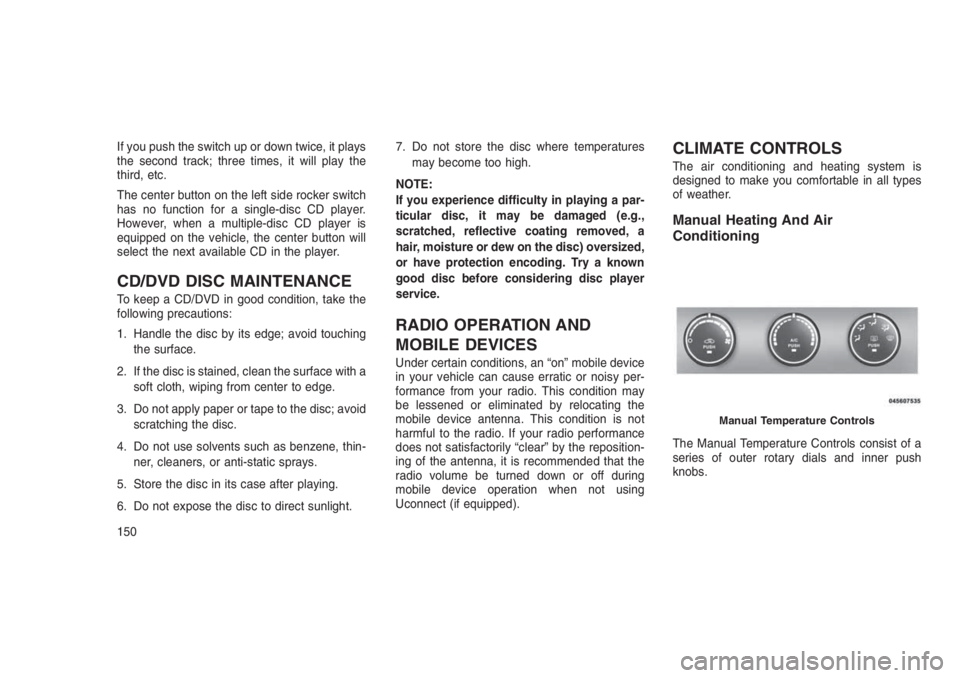
The Manual Temperature Controls consist of a
series of outer rotary dials and inner push
knobs.
Manual Temperature Controls
150
Page 162 of 332
Summer Operation
The engine cooling system must be protected
with a high-quality antifreeze coolant to provide
proper corrosion protection and to protect
against engine overheating. A solution of 50%
OAT (Organic Additive Technology) coolant that
meets the requirements of FCA Material Stan-
dard MS.90032 and 50% water is recom-
mended. Refer to “Maintenance Procedures” in
“Maintaining Your Vehicle” for proper coolant
selection.
Winter Operation
Use of the air Recirculation Mode during winter
months is not recommended because it may
cause window fogging.
Vacation Storage
Anytime you store your vehicle, or keep it out of
service (i.e., vacation) for two weeks or more,
run the air conditioning system at idle for about
five minutes in the fresh air and high blower
settings. This will ensure adequate system lu-
brication to minimize the possibility of compres-
sor damage when the system is started again.Window Fogging
Interior fogging on the windshield can be quickly
removed by turning the mode selector to De-
frost. The Defrost/Floor mode can be used to
maintain a clear windshield and provide suffi-
cient heating. If side window fogging becomes a
problem, increase blower speed. Vehicle win-
dows tend to fog on the inside in mild but rainy
or humid weather.
NOTE:
Recirculate without A/C should not be used
for long periods as fogging may occur.
Side Window Demisters
A side window demister outlet is located at each
end of the instrument panel. These non-
adjustable outlets direct air toward the side
windows when the system is in the FLOOR,
MIX, or DEFROST mode. The air is directed at
the area of the windows through which you view
the outside mirrors.Outside Air Intake
Make sure the air intake, located directly in front
of the windshield, is free of obstructions such as
leaves. Leaves collected in the air intake may
reduce airflow, and if they enter the plenum,
they could plug the water drains. In winter
months, make sure the air intake is clear of ice,
slush, and snow.
A/C Air Filter — If Equipped
The A/C Filter prevents most dust and pollen
from entering the cabin. The filter acts on air
coming from outside the vehicle and recircu-
lated air within the passenger compartment.
Refer to “Maintenance Procedures” in “Main-
taining Your Vehicle” for A/C Air Filter service
information or see your authorized dealer for
service. Refer to “Maintenance Schedules” in
“Maintaining Your Vehicle” for filter service inter-
vals.
158
Page 176 of 332
CAUTION!
Towing the vehicle, coasting, or driving for
any other reason with the transmission in
NEUTRAL can cause severe transmission
damage. Refer to “Recreational Towing” in
“Starting And Operating” and “Towing A Dis-
abled Vehicle” in “What To Do In Emergen-
cies” for further information.
DRIVE (D)
This range should be used for most city and
highway driving. It provides the smoothest up-
shifts and downshifts, and the best fuel
economy. The transmission automatically up-
shifts through underdrive first, second, third,
and fourth gears, direct fifth gear and overdrive
sixth gear. The DRIVE position provides opti-
mum driving characteristics under all normal
operating conditions.
When frequent transmission shifting occurs
(such as when operating the vehicle under
heavy loading conditions, in hilly terrain, travel-
ing into strong head winds, or while towing
heavy trailers), use the AutoStick shift control(refer to “AutoStick (Six-Speed Automatic
Transmission)” in this section for further infor-
mation) to select a lower gear. Under these
conditions, using a lower gear will improve
performance and extend transmission life by
reducing excessive shifting and heat buildup.
If the transmission temperature exceeds normal
operating limits, the transmission controller will
modify the transmission shift schedule and ex-
pand the range of torque converter clutch en-
gagement. This is done to prevent transmission
damage due to overheating. If the transmission
becomes extremely hot, the “Transmission
Temperature Warning Light” may illuminate and
the transmission may operate differently until
the transmission cools down.
During very cold temperatures (-4°F [-20°C] or
below), transmission operation may be modified
depending on engine and transmission tem-
perature as well as vehicle speed. Normal op-
eration will resume once the transmission tem-
perature has risen to a suitable level.
Transmission Limp Home Mode
Transmission function is monitored electroni-
cally for abnormal conditions. If a condition isdetected that could result in transmission dam-
age, Transmission Limp Home Mode is acti-
vated. In this mode, the transmission remains in
fourth gear regardless of which forward gear is
selected. PARK, REVERSE, and NEUTRAL will
continue to operate. The Malfunction Indicator
Light (MIL) may be illuminated. Limp Home
Mode allows the vehicle to be driven to an
authorized dealer for service without damaging
the transmission.
In the event of a momentary problem, the
transmission can be reset to regain all forward
gears by performing the following steps:
1. Stop the vehicle.
2. Shift the transmission into PARK.
3. Turn the ignition switch to the LOCK/OFF
position.
4. Wait approximately 10 seconds.
5. Restart the engine.
6. Shift into the desired gear range. If the
problem is no longer detected, the transmis-
sion will return to normal operation.
172
Page 180 of 332
CAUTION!(Continued)
NEUTRAL can cause severe transmission
damage. Refer to “Recreational Towing” in
“Starting And Operating” and “Towing A Dis-
abled Vehicle” in “What To Do In Emergen-
cies” for further information.
DRIVE (D)
This range should be used for most city and
highway driving. It provides the best fuel
economy. The DRIVE position provides opti-
mum driving characteristics under all normal
operating conditions.
When frequent transmission shifting occurs
(such as when operating the vehicle under
heavy loading conditions, in hilly terrain, travel-
ing into strong head winds, or while towing
heavy trailers), use the AutoStick shift control (if
equipped, refer to"AutoStick (CVT)"in this
section for further information) to select a lower
gear ratio. Under these conditions, using a
lower gear ratio will improve performance and
extend transmission life by reducing excessive
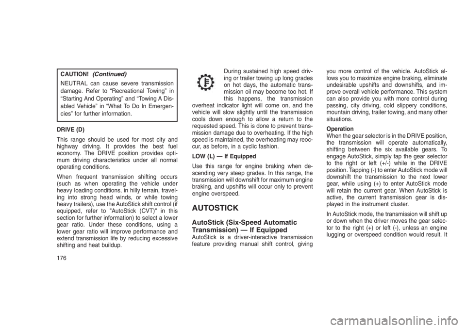
shifting and heat buildup.During sustained high speed driv-
ing or trailer towing up long grades
on hot days, the automatic trans-
mission oil may become too hot. If
this happens, the transmission
overheat indicator light will come on, and the
vehicle will slow slightly until the transmission
cools down enough to allow a return to the
requested speed. This is done to prevent trans-
mission damage due to overheating. If the high
speed is maintained, the overheating may reoc-
cur, as before, in a cyclic fashion.
LOW (L) — If Equipped
Use this range for engine braking when de-
scending very steep grades. In this range, the
transmission will downshift for maximum engine
braking, and upshifts will occur only to prevent
engine overspeed.
AUTOSTICK
AutoStick (Six-Speed Automatic
Transmission) — If Equipped
AutoStick is a driver-interactive transmission
feature providing manual shift control, givingyou more control of the vehicle. AutoStick al-
lows you to maximize engine braking, eliminate
undesirable upshifts and downshifts, and im-
prove overall vehicle performance. This system
can also provide you with more control during
passing, city driving, cold slippery conditions,
mountain driving, trailer towing, and many other
situations.
Operation
When the gear selector is in the DRIVE position,
the transmission will operate automatically,
shifting between the six available gears. To
engage AutoStick, simply tap the gear selector
to the right or left (+/-) while in the DRIVE
position. Tapping (-) to enter AutoStick mode will
downshift the transmission to the next lower
gear, while using (+) to enter AutoStick mode
will retain the current gear. When AutoStick is
active, the current transmission gear is dis-
played in the instrument cluster.
In AutoStick mode, the transmission will shift up
or down when the driver moves the gear selec-
tor to the right (+) or left (-), unless an engine
lugging or overspeed condition would result. It
176
Page 199 of 332
Hill Descent Control (HDC) — If
Equipped
This system maintains vehicle speed while de-
scending hills during off-road driving situations.
HDC will automatically apply the brakes to
control downhill speed to between 4 mph
(7 km/h) and 6 mph (9 km/h) depending on
terrain. The system is activated by placing the
vehicle in “Off-Road” mode and placing the gear
selector in LOW or REVERSE. Refer to “Off-
Road Driving Tips” in “Starting And Operating”
for further information.
When HDC is properly enabled,
the “Hill Decent Control Light” in
the instrument cluster will be
illuminated.
HDC has the capability to sense terrain and will
only activate when the vehicle is descending a
hill. It will not activate on level ground. If desired,
HDC can be fully deactivated by putting the
vehicle into ESC “Full Off” mode. This is done
by pushing and holding the “ESC Off” button for
five seconds. Refer to “Electronic Stability Con-
trol (ESC)” in this section of the manual.HDC operation can be overridden with brake
application to slow the vehicle down below the
HDC control speed. Conversely, if more speed
is desired during HDC control, the accelerator
pedal will increase vehicle speed like normal.
When either the brake or the accelerator is
released, HDC will control the vehicle back to
the original set speed.
HDC is only intended for low speed off-road
driving. At vehicle speeds above 31 mph (50
km/h), HDC will no longer function. If the “HDC
Indicator Light” begins to flash, this indicates
that the brakes are getting too hot and the
vehicle should be stopped to allow the brakes to
cool.
WARNING!
HDC is only intended to assist the driver in
controlling vehicle speed when descending
hills. The driver must remain attentive to the
driving conditions and is responsible for
maintaining a safe vehicle speed.
TIRES — GENERAL
INFORMATION
Tire PressureProper tire inflation pressure is essential to the
safe and satisfactory operation of your vehicle.
Four primary areas are affected by improper tire
pressure:
•Safety and Vehicle Stability
•Economy
•Tread Wear
•Ride Comfort
Safety
WARNING!
•Improperly inflated tires are dangerous
and can cause collisions.
•Underinflation increases tire flexing and
can result in overheating and tire failure.
(Continued)
195