wheel size JEEP PATRIOT 2021 Owner handbook (in English)
[x] Cancel search | Manufacturer: JEEP, Model Year: 2021, Model line: PATRIOT, Model: JEEP PATRIOT 2021Pages: 332, PDF Size: 1.99 MB
Page 43 of 332
may receive information from the front impact
sensors or other system components.
The first stage inflator is triggered immediately
during an impact that requires air bag deploy-
ment. A low energy output is used in less severe
collisions. A higher energy output is used for
more severe collisions.
This vehicle may be equipped with a driver
and/or front passenger seat belt buckle switch
that detects whether the driver or front passen-
ger seat belt is buckled. The seat belt buckle
switch may adjust the inflation rate of the Ad-
vanced Front Air Bags.
WARNING!
•No objects should be placed over or near
the air bag on the instrument panel or
steering wheel because any such objects
could cause harm if the vehicle is in a
collision severe enough to cause the air
bag to inflate.
(Continued)
WARNING!(Continued)
•Do not put anything on or around the air
bag covers or attempt to open them manu-
ally. You may damage the air bags and you
could be injured because the air bags may
no longer be functional. The protective
covers for the air bag cushions are de-
signed to open only when the air bags are
inflating.
•Relying on the air bags alone could lead to
more severe injuries in a collision. The air
bags work with your seat belt to restrain
you properly. In some collisions, air bags
won’t deploy at all. Always wear your seat
belts even though you have air bags.
Advanced Front Air Bag Operation
Advanced Front Air Bags are designed to pro-
vide additional protection by supplementing the
seat belts. Advanced Front Air Bags are not
expected to reduce the risk of injury in rear,
side, or rollover collisions. The Advanced Front
Air Bags will not deploy in all frontal collisions,
including some that may produce substantialvehicle damage — for example, some pole
collisions, truck underrides, and angle offset
collisions.
On the other hand, depending on the type and
location of impact, Advanced Front Air Bags
may deploy in crashes with little vehicle front-
end damage but that produce a severe initial
deceleration.
Because air bag sensors measure vehicle de-
celeration over time, vehicle speed and damage
by themselves are not good indicators of
whether or not an air bag should have de-
ployed.
Seat belts are necessary for your protection in
all collisions, and also are needed to help keep
you in position, away from an inflating air bag.
When the ORC detects a collision requiring the
Advanced Front Air Bags, it signals the inflator
units. A large quantity of non-toxic gas is gen-
erated to inflate the Advanced Front Air Bags.
The steering wheel hub trim cover and the
upper right side of the instrument panel sepa-
rate and fold out of the way as the air bags
inflate to their full size. The Advanced Front Air
39
Page 135 of 332
able to detect or signal low tire pressure as
intended. TPMS malfunctions may occur for a
variety of reasons, including the installation of
replacement or alternate tires or wheels on the
vehicle that prevent the TPMS from functioning
properly. Always check the TPMS malfunction
telltale after replacing one or more tires or
wheels on your vehicle, to ensure that the
replacement or alternate tires and wheels allow
the TPMS to continue to function properly.CAUTION!
The TPMS has been optimized for the origi-
nal equipment tires and wheels. TPMS pres-
sures and warning have been established for
the tire size equipped on your vehicle. Un-
desirable system operation or sensor dam-
age may result when using replacement
equipment that is not of the same size, type,
(Continued)
CAUTION!(Continued)
and/or style. Aftermarket wheels can cause
sensor damage. Using aftermarket tire seal-
ants may cause the Tire Pressure Monitoring
System (TPMS) sensor to become inoper-
able. After using an aftermarket tire sealant it
is recommended that you take your vehicle
to an authorized dealership to have your
sensor function checked.
Electronic Stability Control (ESC) OFF Indicator Light — If Equipped
Yellow Telltale Light What It Means
Electronic Stability Control (ESC) OFF Indicator Light — If Equipped
This light indicates the Electronic Stability Control (ESC) is off.
131
Page 196 of 332
WARNING!(Continued)
•The capabilities of an ESC-equipped ve-
hicle must never be exploited in a reckless
or dangerous manner, which could jeopar-
dize the user’s safety or the safety of
others
•Vehicle modifications, or failure to properly
maintain your vehicle, may change the
handling characteristics of your vehicle,
and may negatively affect the performance
of the ESC system. Changes to the steer-
ing system, suspension, braking system,
tire type and size or wheel size may ad-
versely affect ESC performance. Improp-
erly inflated and unevenly worn tires may
also degrade ESC performance. Any ve-
hicle modification or poor vehicle mainte-
nance that reduces the effectiveness of the
ESC system can increase the risk of loss
of vehicle control, vehicle rollover, per-
sonal injury and death.ESC Operating Modes
The ESC system has three available operating
modes for four–wheel drive equipped vehicles
and two available operating modes for two–
wheel drive equipped vehicles.
Full On (Four-Wheel Drive Models) Or On
(Two-Wheel Drive Models)
This is the normal operating mode for ESC.
Whenever the vehicle is started, the ESC sys-
tem will be in this “On” mode. This mode should
be used for most driving situations. ESC should
only be turned to “Partial Off” or “ESC Off” for
specific reasons as noted below.
Partial Off (Four-Wheel Drive Models) Or On
(Two-Wheel Drive Models)
This mode is entered by momentarily pushing
the “ESC Off” switch. When in “Partial Off”
mode, the TCS portion of ESC, except for the
“limited slip” feature described in the TCS sec-
tion, has been disabled, and the"ESC OFF
Indicator Light"will be illuminated. All other
stability features of ESC function normally. This
mode is intended to be used if the vehicle is in
deep snow, sand or gravel conditions, and morewheel spin than ESC would normally allow is
required to gain traction.
To turn ESC on again, momentarily push the
“ESC Off” switch. This will restore the normal
“ESC On” mode of operation.
NOTE:
To improve the vehicle’s traction when driv-
ing with snow chains, or starting off in deep
snow, sand or gravel, it may be desirable to
switch to the “Partial Off” mode by pushing
the “ESC Off” switch. Once the situation
requiring ESC to be switched to the “Partial
Off” mode is overcome, turn ESC back on by
momentarily pushing the “ESC Off” switch.
This may be done while the vehicle is in
motion.
WARNING!
When in “Partial Off” mode, the TCS func-
tionality of ESC (except for the limited slip
feature described in the TCS section) has
been disabled and the “ESC Off Indicator
(Continued)
192
Page 203 of 332
Run Flat Tires — If EquippedRun Flat tires allow you the capability to drive 50
miles (80 km) at 50 mph (80 km/h) after a rapid
loss of inflation pressure. This rapid loss of
inflation is referred to as the Run Flat mode. A
Run Flat mode occurs when the tire inflation
pressure is of/or below 14 psi (96 kPa). Once a
Run Flat tire reaches the run flat mode it has
limited driving capabilities and needs to be
replaced immediately. A Run Flat tire is not
repairable.
It is not recommended driving a vehicle loaded
at full capacity or to tow a trailer while a tire is in
the run flat mode.
See the tire pressure monitoring section for
more information.
Spare Tires — If Equipped
NOTE:
For vehicles equipped with Tire Service Kit
instead of a spare tire, please refer to “Tire
Service Kit” in “What To Do In Emergencies”
for further information.
CAUTION!
Because of the reduced ground clearance,
do not take your vehicle through an auto-
matic car wash with a compact or limited-use
temporary spare installed. Damage to the
vehicle may result.
Spare Tire Matching Original Equipped Tire
And Wheel — If Equipped
Your vehicle may be equipped with a spare tire
and wheel equivalent in look and function to the
original equipment tire and wheel found on the
front or rear axle of your vehicle. This spare tire
may be used in the tire rotation for your vehicle.
If your vehicle has this option, refer to an
authorized tire dealer for the recommended tire
rotation pattern.
Compact Spare Tire — If Equipped
The compact spare is for temporary emergency
use only. You can identify if your vehicle is
equipped with a compact spare by looking at
the spare tire description on the Tire and Load-
ing Information Placard located on the driver’s
side door opening or on the sidewall of the tire.
Compact spare tire descriptions begin with theletter “T” or “S” preceding the size designation.
Example: T145/80D18 103M.
T, S = Temporary Spare Tire
Since this tire has limited tread life, the original
equipment tire should be repaired (or replaced)
and reinstalled on your vehicle at the first op-
portunity.
Do not install a wheel cover or attempt to mount
a conventional tire on the compact spare wheel,
since the wheel is designed specifically for the
compact spare tire. Do not install more than one
compact spare tire and wheel on the vehicle at
any given time.
WARNING!
Compact spares are for temporary emer-
gency use only. With these spares, do not
drive more than 50 mph (80 km/h). Tempo-
rary use spares have limited tread life. When
the tread is worn to the tread wear indicators,
the temporary use spare tire needs to be
replaced. Be sure to follow the warnings,
(Continued)
199
Page 204 of 332
WARNING!(Continued)
which apply to your spare. Failure to do so
could result in spare tire failure and loss of
vehicle control.
Full Size Spare — If Equipped
The full size spare is for temporary emergency
use only. This tire may look like the originally
equipped tire on the front or rear axle of your
vehicle, but it is not. This spare tire may have
limited tread life. When the tread is worn to the
tread wear indicators, the temporary use full size
spare tire needs to be replaced. Since it is not the
same as your original equipment tire, replace (or
repair) the original equipment tire and reinstall on
the vehicle at the first opportunity.
Limited Use Spare — If EquippedThe limited use spare tire is for temporary emer-
gency use only. This tire is identified by a label
located on the limited use spare wheel. This label
contains the driving limitations for this spare. This
tire may look like the original equipped tire on the
front or rear axle of your vehicle, but it is not.
Installation of this limited use spare tire affects
vehicle handling. Since it is not the same as youroriginal equipment tire, replace (or repair) the
original equipment tire and reinstall on the vehicle
at the first opportunity.
WARNING!
Limited use spares are for emergency use
only. Installation of this limited use spare tire
affects vehicle handling. With this tire, do not
drive more than the speed listed on the limit
use spare wheel. Keep inflated to the cold
tire inflation pressures listed on your Tire and
Loading Information Placard located on the
driver’s side B-Pillar or the rear edge of the
driver’s side door. Replace (or repair) the
original equipment tire at the first opportunity
and reinstall it on your vehicle. Failure to do
so could result in loss of vehicle control.
Tire SpinningWhen stuck in mud, sand, snow, or ice condi-
tions, do not spin your vehicle’s wheels above
30 mph (48 km/h) or for longer than 30 seconds
continuously without stopping.Refer to “Freeing A Stuck Vehicle” in “What To
Do In Emergencies” for further information.
WARNING!
Fast spinning tires can be dangerous.
Forces generated by excessive wheel
speeds may cause tire damage or failure. A
tire could explode and injure someone. Do
not spin your vehicle’s wheels faster than
30 mph (48 km/h) for more than 30 seconds
continuously when you are stuck, and do not
let anyone near a spinning wheel, no matter
what the speed.
Tread Wear IndicatorsTread wear indicators are in the original equip-
ment tires to help you in determining when your
tires should be replaced.
200
Page 206 of 332
you ever replace a wheel, make sure that the
wheel’s specifications match those of the origi-
nal wheels.
It is recommended you contact your authorized
tire dealer or original equipment dealer with any
questions you may have on tire specifications or
capability. Failure to use equivalent replace-
ment tires may adversely affect the safety,
handling, and ride of your vehicle.
WARNING!
•Do not use a tire, wheel size or rating other
than that specified for your vehicle. Some
combinations of unapproved tires and
wheels may change suspension dimen-
sions and performance characteristics, re-
sulting in changes to steering, handling,
and braking of your vehicle. This can
cause unpredictable handling and stress
to steering and suspension components.
You could lose control and have a collision
resulting in serious injury or death. Use
(Continued)
WARNING!(Continued)
only the tire and wheel sizes with load
ratings approved for your vehicle.
•Never use a tire with a smaller load index
or capacity, other than what was originally
equipped on your vehicle. Using a tire with
a smaller load index could result in tire
overloading and failure. You could lose
control and have a collision.
•Failure to equip your vehicle with tires
having adequate speed capability can re-
sult in sudden tire failure and loss of ve-
hicle control.
CAUTION!
Replacing original tires with tires of a differ-
ent size may result in false speedometer and
odometer readings.
TIRE CHAINS (TRACTION
DEVICES)
Use of traction devices require sufficient tire-to-
body clearance. Follow these recommenda-
tions to guard against damage.
•Traction device must be of proper size for the
tire, as recommended by the traction device
manufacturer.
•Install on Front Tires.
•A 215/60R17 96H tire with the use of a
traction device that meets the SAE type
"Class S"specification is recommended.
WARNING!
Using tires of different size and type (M+S,
Snow) between front and rear axles can
cause unpredictable handling. You could
lose control and have a collision.
202
Page 209 of 332
CAUTION!
•The TPMS has been optimized for the
original equipment tires and wheels. TPMS
pressures and warning have been estab-
lished for the tire size equipped on your
vehicle. Undesirable system operation or
sensor damage may result when using
replacement equipment that is not of the
same size, type, and/or style. Aftermarket
wheels can cause sensor damage.
•Using aftermarket tire sealants may cause
the Tire Pressure Monitoring System
(TPMS) sensor to become inoperable. Af-
ter using an aftermarket tire sealant it is
recommended that you take your vehicle
to an authorized dealership to have your
sensor function checked.
•After inspecting or adjusting the tire pres-
sure always reinstall the valve stem cap.
This will prevent moisture and dirt from
entering the valve stem, which could dam-
age the TPMS sensor.NOTE:
•The TPMS is not intended to replace nor-
mal tire care and maintenance or to pro-
vide warning of a tire failure or condition.
•The TPMS should not be used as a tire
pressure gauge while adjusting your tire
pressure.
•Driving on a significantly under-inflated
tire causes the tire to overheat and can
lead to tire failure. Under-inflation also
reduces fuel efficiency and tire tread life,
and may affect the vehicle’s handling and
stopping ability.
•The TPMS is not a substitute for proper
tire maintenance, and it is the driver’s
responsibility to maintain correct tire
pressure using an accurate tire gauge,
even if under-inflation has not reached
the level to trigger illumination of the Tire
Pressure Monitoring Telltale Light.
•Seasonal temperature changes will affect
tire pressure, and the TPMS will monitor
the actual tire pressure in the tire.Base System
This is the TPMS warning indicator
located in the instrument cluster.
The TPMS uses wireless technology with wheel
rim mounted electronic sensors to monitor tire
pressure levels. Sensors, mounted to each
wheel as part of the valve stem, transmit tire
pressure readings to the Receiver Module.
NOTE:
It is particularly important for you to check
the tire pressure in all of the tires on your
vehicle regularly and to maintain the proper
pressure.
The TPMS consists of the following compo-
nents:
•Receiver Module.
•Four Tire Pressure Monitoring Sensors.
•Tire Pressure Monitoring Telltale Light.
205
Page 218 of 332
Trailer Sway ControlThe trailer sway control can be a mechanical
telescoping link that can be installed between the
hitch receiver and the trailer tongue that typically
provides adjustable friction associated with the
telescoping motion to dampen any unwanted
trailer swaying motions while traveling.
If equipped, the electronic Trailer Sway Control
(TSC) recognizes a swaying trailer and auto-
matically applies individual wheel brakes and/or
reduces engine power to attempt to eliminate
the trailer sway.
Weight-Carrying Hitch
A weight-carrying hitch supports the trailer
tongue weight, just as if it were luggage located
at a hitch ball or some other connecting point of
the vehicle. These kinds of hitches are the most
popular on the market today and they are
commonly used to tow small and medium sized
trailers.
Weight-Distributing Hitch
A weight-distributing system works by applying
leverage through spring (load) bars. They are
typically used for heavier loads to distribute
trailer tongue weight to the tow vehicle’s frontaxle and the trailer axle(s). When used in ac-
cordance with the manufacturer’s directions, it
provides for a more level ride, offering more
consistent steering and brake control thereby
enhancing towing safety. The addition of a
friction/hydraulic sway control also dampens
sway caused by traffic and crosswinds and
contributes positively to tow vehicle and trailer
stability. Trailer sway control and a weight dis-
tributing (load equalizing) hitch are recom-
mended for heavier Tongue Weights (TW) and
may be required depending on vehicle and
trailer configuration/loading to comply with
Gross Axle Weight Rating (GAWR) require-
ments.
WARNING!
•An improperly adjusted Weight Distributing
Hitch system may reduce handling, stabil-
ity, braking performance, and could result
in a collision.
(Continued)
WARNING!(Continued)
•Weight Distributing Systems may not be
compatible with Surge Brake Couplers.
Consult with your hitch and trailer manu-
facturer or a reputable Recreational Ve-
hicle dealer for additional information.
Breakaway Cable AttachmentEuropean braking regulations for braked trailers
up to 7,700 lbs (3,500 kg), require trailers to be
fitted with either a secondary coupling or break-
away cable.
The recommended location for attaching the
normal trailer’s breakaway cable is in the
stamped slot located on the sidewall of the hitch
receiver.
214
Page 232 of 332
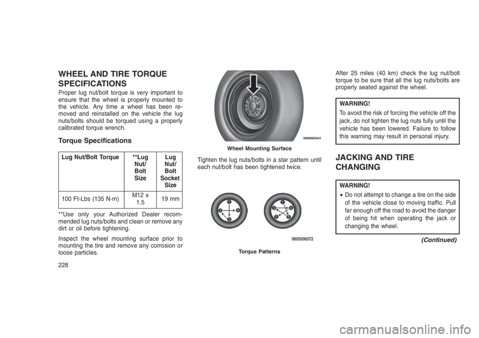
WHEEL AND TIRE TORQUE
SPECIFICATIONS
Proper lug nut/bolt torque is very important to
ensure that the wheel is properly mounted to
the vehicle. Any time a wheel has been re-
moved and reinstalled on the vehicle the lug
nuts/bolts should be torqued using a properly
calibrated torque wrench.
Torque Specifications
Lug Nut/Bolt Torque **Lug
Nut/
Bolt
SizeLug
Nut/
Bolt
Socket
Size
100 Ft-Lbs (135 N·m)M12 x
1.519 mm
**Use only your Authorized Dealer recom-
mended lug nuts/bolts and clean or remove any
dirt or oil before tightening.
Inspect the wheel mounting surface prior to
mounting the tire and remove any corrosion or
loose particles.Tighten the lug nuts/bolts in a star pattern until
each nut/bolt has been tightened twice.After 25 miles (40 km) check the lug nut/bolt
torque to be sure that all the lug nuts/bolts are
properly seated against the wheel.
WARNING!
To avoid the risk of forcing the vehicle off the
jack, do not tighten the lug nuts fully until the
vehicle has been lowered. Failure to follow
this warning may result in personal injury.
JACKING AND TIRE
CHANGING
WARNING!
•Do not attempt to change a tire on the side
of the vehicle close to moving traffic. Pull
far enough off the road to avoid the danger
of being hit when operating the jack or
changing the wheel.
(Continued)
Wheel Mounting Surface
Torque Patterns
228