ESP JEEP RENEGADE 2015 1.G User Guide
[x] Cancel search | Manufacturer: JEEP, Model Year: 2015, Model line: RENEGADE, Model: JEEP RENEGADE 2015 1.GPages: 678, PDF Size: 29.84 MB
Page 127 of 678
MANUAL mode (the set temperatures will flash on the
display). The blower speed is the same in all the zones of
the passenger compartment.
Adjusting The Air Temperature
Rotate the Driver Temperature Control, or the Passenger
Temperature Control, dial clockwise or counter-
clockwise, to adjust the air temperature in the front left
(Driver Temperature Control) or right (Passenger Tem-
perature Control) zone of the passenger compartment.
The set temperatures are shown on the displays.
Push the SYNC button to align the air temperature
between the two zones.
Turn the Passenger Temperature Control knob to return
to the separate management of air temperatures in the
two zones.
Turning the control knobs completely in one direction or
the other activates the#HI#(maximum heating) or#LO#
(maximum cooling) functions respectively.
To deactivate these functions, turn the temperature knob
to the desired temperature.
Air Distribution Selection
By pushing the Mode Control buttons (Defrost/Panel/
Floor buttons), it is possible to set one of the seven
possible air distributions manually by activating one or
more mode buttons:
•Defrost Mode – Air flow to the windshield and front
side window diffusers to defrost them. Use Defrost
mode with maximum temperature settings for best
windshield and side window defrosting. When the
defrost mode is selected, the blower will automatically
default to medium-high.
4
GETTING TO KNOW YOUR VEHICLE 125
Page 128 of 678
•Panel Mode – Air flow is distributed between the
footwell diffusers and the central and side instrument
panel vents.
•Floor Mode – Air flow is directed from the front and
rear footwell diffusers.
•Floor and Panel Modes – Air flow is distributed
between the footwell diffusers and the central and side
instrument panel vents.
•Floor and Defrost Modes – Air flow distributed be-
tween footwell diffusers and windshield and front side
window defrosting diffusers. This distribution setting
allows the passenger compartment to be warmed
effectively and prevents the windows from misting.
•Defrost and Panel Modes – Air flow distribution
between windshield defrosting diffusers and side and
central instrument panel vents.
•Defrost, Panel and Floor Modes – Air flow distribution
to all the diffusers.
NOTE:Air always flows from the side instrument panel
diffusers: it is, however, possible to interrupt the air flow
by operating the wheel located near the corresponding
vents.
In AUTO mode, the climate control system automatically
manages air distribution (LEDs on the Mode Control
buttons are off).
When set manually, the air distribution is indicated by
the LEDs on the selected buttons turning on.
In combined function mode, functions are enabled to-
gether with those already set when the relevant button is
pushed. If a button whose function is already active is
pushed, the operation is cancelled and the corresponding
LED turns off.
126 GETTING TO KNOW YOUR VEHICLE
Page 129 of 678
To restore automatic control of the air distribution after a
manual selection, push the AUTO button.
Adjusting The Fan Speed
Rotate the Blower Control knob to increase/decrease the
fan speed.
The speed is indicated by the eight Blower Control
Indicator LEDs, located above the Blower Control knob,
turning on.
•Maximum blower speed = all LEDs illuminated
•Minimum blower speed = one LED illuminated
The blower can only be turned off if the A/C compressor
has been turned off by pushing the A/C Control button.
NOTE:To restore automatic control of the fan speed after
a manual adjustment, push the AUTO button.
AUTO Button
When the AUTO button is pushed (LED illuminated), the
Climate Control system automatically adjusts the follow-
ing settings in the corresponding zones:
•Quantity and distribution of the air introduced into the
passenger compartment.
•Climate Control system compressor.
•Air Recirculation.
Cancelling all previous manual adjustments.
This is indicated by the AUTO button LED turning on.
If the AUTO button is pushed when the AUTO LED is on,
the system changes to manual mode; it displays the
current flow and distribution status, which will no longer
be managed automatically.
4
GETTING TO KNOW YOUR VEHICLE 127
Page 131 of 678
In automatic operation, recirculation is managed auto-
matically by the system according to outside environ-
mental conditions.
NOTE:
•Use of the recirculation system makes it possible to
reach the required heating/cooling conditions faster. It
is not recommended to use it on rainy/cold days as it
would considerably increase the possibility of the
windows misting up inside (especially if the Climate
Control system is off). When the outside temperature
is low, recirculation is forced off (air drawn in from the
outside) to prevent the windows from misting up.
•It is not recommended to use internal air recirculation
when the outside temperature is low, since the win-
dows could mist up rapidly.
Climate Control System Compressor
Push the A/C Control button to activate/deactivate the
compressor (activation is indicated by the LED on the
button turning on).
The system remembers that the compressor has been
turned off, even after the engine has stopped.
When the compressor is turned off, the system deacti-
vates air recirculation to prevent the windows from
misting up.
Pushing the A/C button will stop AUTO MODE (AUTO
LED will turn off). To restore automatic control of com-
pressor, push the AUTO button again.
NOTE:With the compressor off, air cannot be introduced
to the passenger compartment with a temperature lower
than the outside temperature. Under certain environmen-
tal conditions, windows could mist rapidly since the air
is not dehumidified.
4
GETTING TO KNOW YOUR VEHICLE 129
Page 158 of 678
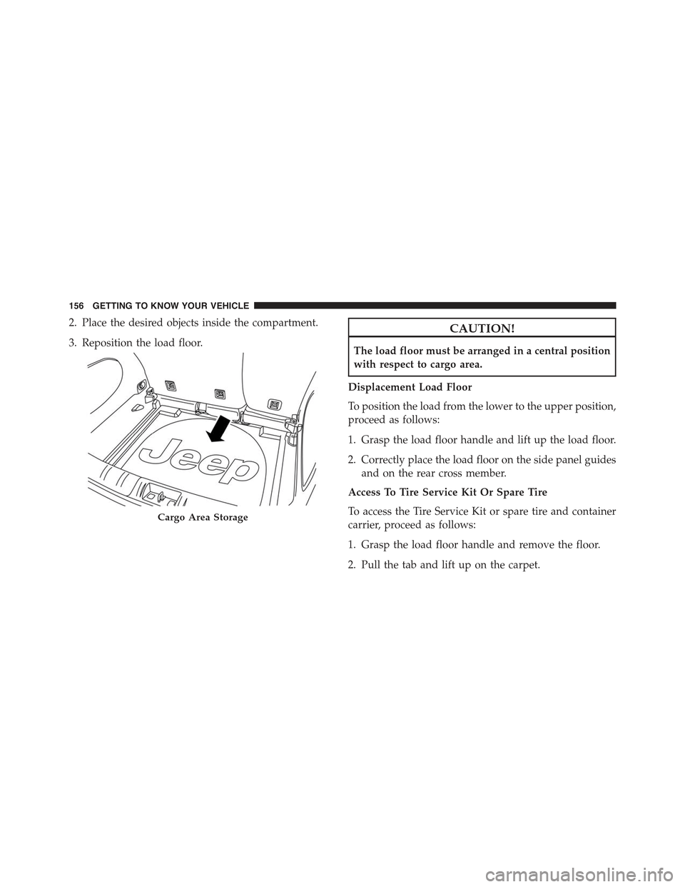
2. Place the desired objects inside the compartment.
3. Reposition the load floor.
CAUTION!
The load floor must be arranged in a central position
with respect to cargo area.
Displacement Load Floor
To position the load from the lower to the upper position,
proceed as follows:
1. Grasp the load floor handle and lift up the load floor.
2. Correctly place the load floor on the side panel guides
and on the rear cross member.
Access To Tire Service Kit Or Spare Tire
To access the Tire Service Kit or spare tire and container
carrier, proceed as follows:
1. Grasp the load floor handle and remove the floor.
2. Pull the tab and lift up on the carpet.
Cargo Area Storage
156 GETTING TO KNOW YOUR VEHICLE
Page 174 of 678
ROOF LUGGAGE RACK — IF EQUIPPED
Your vehicle may be equipped with a Roof Luggage Rack
for transporting accessories.
Crossbars should always be used whenever cargo is
placed on the Roof Luggage Rack. Check the straps
frequently to be sure that the load remains securely
attached.
NOTE:Crossbars can be purchased at a authorized
dealer through Mopar® parts. External racks do not
increase the total load carrying capacity of the vehicle. Be
sure that the total occupant and luggage load inside the
vehicle, plus the load on the Roof Luggage Rack, do not
exceed the maximum vehicle load capacity.
The load carried on the roof, when equipped with a
luggage rack, must not exceed 150 lbs (68 kg), and it
should be uniformly distributed over the cargo area.
Do not use the retractable roof when using the crossbars.
CAUTION!
•To avoid damage to the Roof Luggage Rack and
vehicle, do not exceed the maximum roof rack load
capacity. Always distribute heavy loads as evenly
as possible and secure the load appropriately.
•Long loads, which extend over the windshield,
such as wood panels or surfboards, should be
secured to both the front and rear of the vehicle.
•Place a blanket or other protection between the
surface of the roof and the load.
•Travel at reduced speeds and turn corners carefully
when carrying large or heavy loads on the roof
rack. Wind forces, due to natural causes or nearby
truck traffic, can add sudden upward loads. This is
especially true on large flat loads and may result in
damage to the cargo or your vehicle.
172 GETTING TO KNOW YOUR VEHICLE
Page 191 of 678
proper pressure. Driving on a significantly under-
inflated tire causes the tire to overheat and can lead to
tire failure. Under-inflation also reduces fuel effi-
ciency and tire tread life, and may affect the vehicle’s
handling and stopping ability.
Please note that the TPMS is not a substitute for
proper tire maintenance, and it is the driver ’s respon-
sibility to maintain correct tire pressure, even if
under-inflation has not reached the level to trigger
illumination of the TPMS low tire pressure telltale.
Your vehicle has also been equipped with a TPMS
malfunction indicator to indicate when the system is
not operating properly. The TPMS malfunction indi-
cator is combined with the low tire pressure telltale.
When the system detects a malfunction, the telltale
will flash for approximately one minute and then
remain continuously illuminated. This sequence will
continue upon subsequent vehicle start-ups as long
as the malfunction exists. When the malfunction
indicator is illuminated, the system may not be able
to detect or signal low tire pressure as intended.
TPMS malfunctions may occur for a variety of rea-
sons, including the installation of replacement or
alternate tires or wheels on the vehicle that prevent
the TPMS from functioning properly. Always check
the TPMS malfunction telltale after replacing one or
more tires or wheels on your vehicle, to ensure that
the replacement or alternate tires and wheels allow
the TPMS to continue to function properly.
CAUTION!
The TPMS has been optimized for the original
equipment tires and wheels. TPMS pressures and
warning have been established for the tire size
(Continued)
5
GETTING TO KNOW YOUR INSTRUMENT PANEL 189
Page 199 of 678
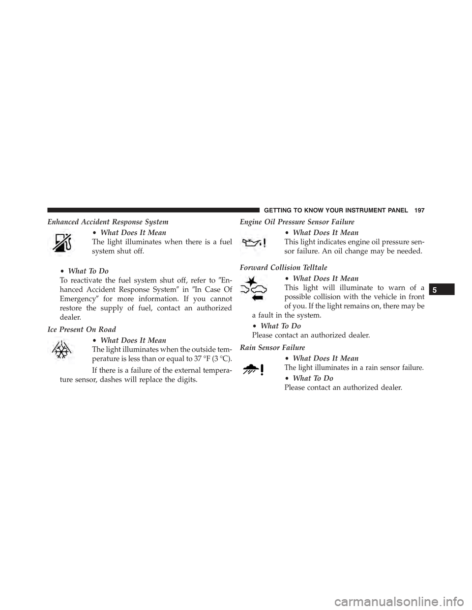
Enhanced Accident Response System
•What Does It Mean
The light illuminates when there is a fuel
system shut off.
•What To Do
To reactivate the fuel system shut off, refer to#En-
hanced Accident Response System#in#In Case Of
Emergency#for more information. If you cannot
restore the supply of fuel, contact an authorized
dealer.
Ice Present On Road
•What Does It Mean
The light illuminates when the outside tem-
perature is less than or equal to 37 °F (3 °C).
If there is a failure of the external tempera-
ture sensor, dashes will replace the digits.
Engine Oil Pressure Sensor Failure
•What Does It Mean
This light indicates engine oil pressure sen-
sor failure. An oil change may be needed.
Forward Collision Telltale
•What Does It Mean
This light will illuminate to warn of a
possible collision with the vehicle in front
of you. If the light remains on, there may be
a fault in the system.
•What To Do
Please contact an authorized dealer.
Rain Sensor Failure
•What Does It Mean
The light illuminates in a rain sensor failure.
•What To Do
Please contact an authorized dealer.
5
GETTING TO KNOW YOUR INSTRUMENT PANEL 197
Page 201 of 678
Enhanced Accident Response System Failure
•What Does It Mean
The light illuminates in case of failure of
the Enhanced Accident Response System.
•What To Do
Please contact an authorized dealer as soon as pos-
sible.
LaneSense System Failure
•What Does It Mean
The light illuminates if there is dirt on the
windshield that could interfere with the
proper operation of the camera.
For vehicles equipped with multifunctional display,
the icon is located on the top right side of the display.
LaneSense System Failure
The light illuminates on if there is a fault in the
LaneSense system.
•What To Do
Clean the windshield, using a soft, clean cloth, being
careful not to scratch it. If the light remains on,
contact an authorized dealer.
Loose Fuel Filler Cap Message Indicator
•What Does It Mean
This light will illuminate to indicate the
fuel filler cap is loose.
•What To Do
Properly close the filler cap.
Automatic Headlights Failure
•What Does It Mean
The light turns on to indicate the failure of
the main beam automatic headlights.
•What To Do
Please contact an authorized dealer as soon as pos-
sible.
5
GETTING TO KNOW YOUR INSTRUMENT PANEL 199
Page 229 of 678
•Engines may idle at higher speeds during warm-up,
which could cause rear wheels to spin and result in
loss of vehicle control. Be especially careful while
driving on slippery roads, in close-quarter maneuver-
ing, parking, or stopping.
•Do not drive too fast for road conditions, especially
when roads are wet or slushy. A wedge of water can
build up between the tire tread and the road. This
hydroplaning action can cause loss of traction, braking
ability, and control.
•After going through deep water or a car wash, brakes
may become wet, resulting in decreased performance
and unpredictable braking action. Dry the brakes by
gentle, intermittent pedal action while driving at very
slow speeds.
Traction Control System (TCS)
This system monitors the amount of wheel spin of each of
the driven wheels. If wheel spin is detected, brake
pressure is applied to the slipping wheel(s) and engine
power is reduced to provide enhanced acceleration and
stability. A feature of the TCS system, Brake Limited
Differential (BLD), functions similar to a limited slip
differential and controls the wheel spin across a driven
axle. If one wheel on a driven axle is spinning faster than
the other, the system will apply the brake of the spinning
wheel. This will allow more engine torque to be applied
to the wheel that is not spinning. This feature remains
active even if TCS and ESC are in the “Partial Off” mode
or the “Full Off” mode. Refer to “Electronic Stability
Control (ESC)” in this section for further information.
Brake Assist System (BAS)
The BAS is designed to optimize the vehicle’s braking
capability during emergency braking maneuvers. The
system detects an emergency braking situation by sens-
ing the rate and amount of brake application and then
applies optimum pressure to the brakes. This can help
6
SAFETY 227