deactivate JEEP RENEGADE 2015 1.G User Guide
[x] Cancel search | Manufacturer: JEEP, Model Year: 2015, Model line: RENEGADE, Model: JEEP RENEGADE 2015 1.GPages: 678, PDF Size: 29.84 MB
Page 218 of 678
•Buzzer Volume
•Maintenance Brakes (If Equipped): activation of the
procedure to carry out braking system maintenance
•Auto Park Brake (If Equipped): enable/disable auto-
insertion of the Electric Parking Brake
$Lights$
By selecting the item#Lights,#you can make the follow-
ing adjustments:
•Headlight Off Delay: set the delay for headlight shut-
off after engine shutoff
•Lights in the opening: activate the direction indicators
when opening the doors
•Headlight Sensor: adjust the sensitivity of headlight
brightness
•Auto. High Beam: activate/deactivate the automatic
main beam headlights (If Equipped)
•Daytime Lights: activate/deactivate the daytime run-
ning lights
•Cornering lights: activate/deactivate the cornering
lights (If Equipped)
$Doors & Safety$
By selecting the item#Doors & Safety,#you can make the
following adjustments:
•Auto Door Lock: activate/deactivate the automatic
locking of the doors with the vehicle moving
•Auto Unlock On Exit: automatic unlocking of the
doors when exiting the vehicle
•Flash Light with Lock: activate the direction indicators
when closing the doors
216 GETTING TO KNOW YOUR INSTRUMENT PANEL
Page 219 of 678
•Sound Horn With Lock: activate/deactivate the horn
when pressing the LOCK button on the RKE. The
options are#Off,##First Press,” and#Second Press.#
•Horn With Remote Start: activate/deactivate the horn
at the Remote Starting of the engine with the RKE.
•Unlock On First Press Of Key Fob (vehicles without
Passive Entry): allows you to choose whether to un-
lock all the doors or only the driver’s side door on the
first push of the UNLOCK button on the RKE
•Remote Door Unlock: allows you to open the driver
door only on the first push of the UNLOCK button on
the RKE
•Passive Entry (If Equipped) : activate the automatic
locking of the doors
$Compass$
By selecting the item#Compass,#you can view and
change the following settings:
•Calibration
•Variance
Calibration
The compass calibrates itself automatically, so you may
not need any initial calibration. It is required to confirm
the calibration by pressing the OK button and drive in
one or more 360–degree turns (in an area free from large
metal or metallic objects). The compass will now function
normally.
5
GETTING TO KNOW YOUR INSTRUMENT PANEL 217
Page 230 of 678
reduce braking distances. The BAS complements the
Anti-Lock Brake System (ABS). Applying the brakes very
quickly results in the best BAS assistance. To receive the
benefit of the system, you must apply continuous brak-
ing pressure during the stopping sequence, (do not
“pump” the brakes). Do not reduce brake pedal pressure
unless braking is no longer desired. Once the brake pedal
is released, the BAS is deactivated.
WARNING!
The Brake Assist System (BAS) cannot prevent the
natural laws of physics from acting on the vehicle,
nor can it increase the traction afforded by prevailing
road conditions. BAS cannot prevent collisions, in-
cluding those resulting from excessive speed in
turns, driving on very slippery surfaces, or hydro-
planing. The capabilities of a BAS-equipped vehicle
(Continued)
WARNING!(Continued)
must never be exploited in a reckless or dangerous
manner, which could jeopardize the user’s safety or
the safety of others.
Electronic Roll Mitigation (ERM)
This system anticipates the potential for wheel lift by
monitoring the driver ’s steering wheel input and the
speed of the vehicle. When ERM determines that the rate
of change of the steering wheel angle and vehicle’s speed
are sufficient to potentially cause wheel lift, it then
applies the appropriate brake and may also reduce
engine power to lessen the chance that wheel lift will
occur. ERM will only intervene during very severe or
evasive driving maneuvers. ERM can only reduce the
chance of wheel lift occurring during severe or evasive
228 SAFETY
Page 234 of 678
Activating HDC
Once HDC is enabled, it will activate automatically if
driven down a grade of sufficient magnitude (greater
than approximately 8%). The set speed for HDC is
selectable by the driver and can be adjusted using brake
and throttle input.
Driver Override:
The driver may override HDC activation with throttle or
brake application at anytime.
Deactivating HDC
HDC will be deactivated but remain available if any of
the following conditions occur:
•Driver overrides HDC set speed with throttle or brake
application.
•Vehicle speed exceeds 7.5 mph (12 km/h) but remains
below 25 mph (40 km/h).
•Vehicle is on a downhill grade of insufficient magni-
tude (less than approximately 8%), is on level ground,
or is on an uphill grade.
•Vehicle is shifted to PARK.
Disabling HDC
HDC will be deactivated and disabled if any of the
following conditions occur:
•The driver pushes the HDC switch.
•The driveline is shifted out of 4WD Low Range.
•Driver door opens.
•The vehicle is driven greater than 25 mph (40 km/h)
(HDC exits immediately.)
232 SAFETY
Page 235 of 678
Feedback To The Driver:
The instrument cluster has an HDC icon and the HDC
switch has an LED which offer feedback to the driver
about the state HDC is in.
•The cluster icon and switch lamp will illuminate and
remain solid when HDC is enabled or activated. This is
the normal operating condition for HDC.
•The cluster icon and switch lamp will flash for several
seconds then extinguish when the driver pushes the
HDC switch when enable conditions have not been met.
•The cluster icon and switch lamp will flash for several
seconds then extinguish when HDC deactivates due to
excess speed.
•The cluster icon and switch lamp will flash when HDC
deactivates due to overheated brakes. The flashing will
stop and HDC will activate again once the brakes have
cooled sufficiently.
The Hill Descent Switch is located within the Selec-
Terrain™ knob in the upper right position.
WARNING!
HDC is only intended to assist the driver in control-
ling vehicle speed when descending hills. The driver
must remain attentive to the driving conditions and
is responsible for maintaining a safe vehicle speed.
Electronic Stability Control (ESC)
This system enhances directional control and stability of
the vehicle under various driving conditions. ESC cor-
rects for oversteering or understeering of the vehicle by
applying the brake of the appropriate wheel to assist in
counteracting the oversteer or understeer condition. En-
gine power may also be reduced to help the vehicle
maintain the desired path.
6
SAFETY 233
Page 245 of 678
Driver Override:
The driver may override SSC activation with throttle or
brake application at any time.
Deactivating SSC
SSC will be deactivated but remain available if any of the
following conditions occur:
•Driver overrides SSC set speed with throttle or brake
application.
•Vehicle speed exceeds 20 mph (32 km/h) but remains
below 40 mph (64 km/h).
•Vehicle is shifted to park.
Disabling SSC
SSC will deactivate and be disabled if any of the follow-
ing conditions occur:
•The driver presses the SSC switch.
•The driveline is shifted out of 4WD Low Range.
•The parking brake is applied.
•Driver door opens.
•The vehicle is driven greater than 20 mph (32 km/h)
for greater than 70 seconds.
•The vehicle is driven greater than 40 mph (64 km/h)
(SSC exits immediately).
Feedback To The Driver:
The instrument cluster has an SSC icon and the SSC
switch has an LED which offer feedback to the driver
about the state SSC is in.
•The cluster icon and switch lamp will illuminate and
remain on solid when SSC is enabled or activated. This
is the normal operating condition for SSC.
6
SAFETY 243
Page 246 of 678
•The cluster icon and switch lamp will flash for several
seconds then extinguish when the driver presses the
SSC switch but enable conditions are not met.
•The cluster icon and switch lamp will flash for several
seconds then extinguish when SSC disables due to
excess speed.
•The cluster icon and switch lamp will flash then
extinguish when SSC deactivates due to overheated
brakes.
WARNING!
SSC is only intended to assist the driver in control-
ling vehicle speed when driving in off road condi-
tions. The driver must remain attentive to the driving
conditions and is responsible for maintaining a safe
vehicle speed.
FORWARD COLLISION WARNING (FCW) WITH
MITIGATION — IF EQUIPPED
Forward Collision Warning (FCW) With Mitigation
Operation
The Forward Collision Warning (FCW) system with
mitigation provides the driver with audible warnings,
visual warnings (within the EVIC/DID), and may apply
a brake jerk to warn the driver when it detects a potential
frontal collision. The warnings and limited braking are
intended to provide the driver with enough time to react,
avoid or mitigate the potential collision.
NOTE:FCW monitors the information from the forward
looking sensors as well as the Electronic Brake Controller
(EBC), to calculate the probability of a forward collision.
When the system determines that a forward collision is
probable, the driver will be provided with audible and
visual warnings and may provide a brake jerk warning.
244 SAFETY
Page 248 of 678
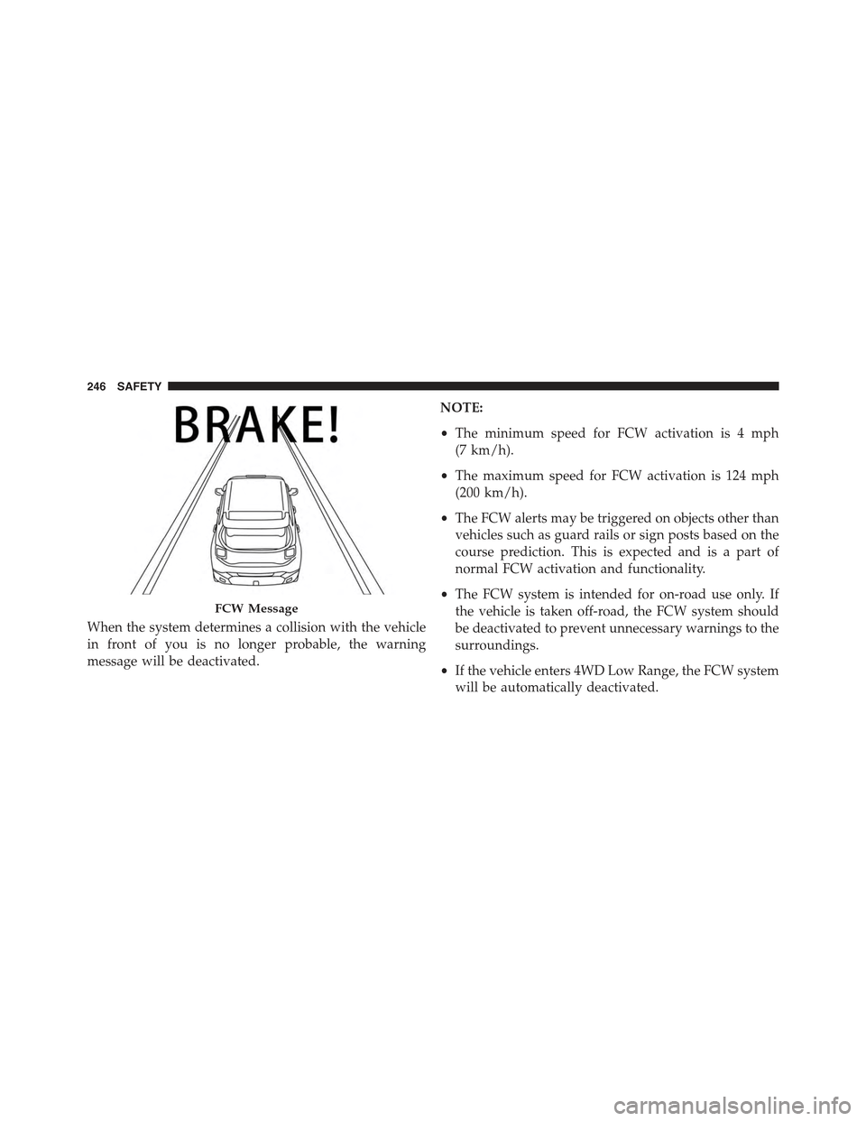
When the system determines a collision with the vehicle
in front of you is no longer probable, the warning
message will be deactivated.
NOTE:
•The minimum speed for FCW activation is 4 mph
(7 km/h).
•The maximum speed for FCW activation is 124 mph
(200 km/h).
•The FCW alerts may be triggered on objects other than
vehicles such as guard rails or sign posts based on the
course prediction. This is expected and is a part of
normal FCW activation and functionality.
•The FCW system is intended for on-road use only. If
the vehicle is taken off-road, the FCW system should
be deactivated to prevent unnecessary warnings to the
surroundings.
•If the vehicle enters 4WD Low Range, the FCW system
will be automatically deactivated.
FCW Message
246 SAFETY
Page 257 of 678

respective seat belts are buckled. The driver should
instruct all other occupants to buckle their seat belts. If an
outboard front seat belt is unbuckled while traveling at
speeds greater than 5 MPH (8 km/h), BeltAlert will
provide both audio and visual notification. The sequence
is interrupted when the reverse gear is selected or speed
is under 5 mph (8 km/h). In case of interruption, the
sequence will restart when speed is again over 5 mph
(8 km/h).
The outboard front passenger seat BeltAlert is not active
when the outboard front passenger seat is unoccupied.
BeltAlert may be triggered when an animal or heavy
object is on the outboard front passenger seat or when the
seat is folded flat (if equipped). It is recommended that
pets be restrained in the rear seat (if equipped) in pet
harnesses or pet carriers that are secured by seat belts,
and cargo is properly stowed.
In addition to the BeltAlert warning sequence that begins
when the vehicle speed is over 5MPH (8km/h), when the
ignition switch is turned to ON/RUN from OFF position
with the vehicle stopped, only for the driver (if unbelted),
an audible chime will sound for a few seconds.
BeltAlert can be activated or deactivated by your autho-
rized dealer. Chrysler Group LLC does not recommend
deactivating BeltAlert.
NOTE:If BeltAlert has been deactivated, the Seat Belt
Reminder Light will continue to illuminate while the
driver ’s or outboard front passenger ’s (if equipped with
BeltAlert) seat belt remains unbuckled. Even though
BeltAlert is deactivated, the initial warning cycle (both
the chime and the light) could be executed for few
seconds.
6
SAFETY 255
Page 283 of 678
Enhanced Accident Response System
In the event of an impact, if the communication network
remains intact, and the power remains intact, depending
on the nature of the event, the ORC will determine
whether to have the Enhanced Accident Response Sys-
tem perform the following functions:
•Cut off fuel to the engine.
•Flash hazard lights as long as the battery has power or
until the ignition is placed in the “OFF” position. The
customer can deactivate the hazard lights flasher
pressing the Hazard flasher button also before the
rearm procedure.
•Turn on the interior lights, which remain on as long as
the battery has power or for 15 minutes from the
intervention of the Enhanced Accident Response Sys-
tem.
•Unlock the doors automatically.
•Turn off the Fuel Pump Heater.
•Turn Off the HVAC Blower Motor.
•Close the HVAC Circulation Door.
System Reset Procedure
Depending on the nature of the event the left and right
turn signal lights, located in the instrument panel, may
both be blinking and will continue to blink until the
ignition switch is turned to the OFF position. After an
accident, turn the ignition switch to STOP/OFF position,
check that there aren’t any losses of fuel/liquids. In order
to move your vehicle to the side of the road, you must
follow the system reset procedure.
6
SAFETY 281