brake JEEP RENEGADE 2015 1.G Owner's Manual
[x] Cancel search | Manufacturer: JEEP, Model Year: 2015, Model line: RENEGADE, Model: JEEP RENEGADE 2015 1.GPages: 220, PDF Size: 34.11 MB
Page 162 of 220
- Brake Warning Light
This light monitors various brake functions, including brake fluid level and parking
brake application. If the brake light turns on, it may indicate that the parking brake
is applied, that the brake fluid level is low, or that there is a problem with the
anti-lock brake system reservoir.
If the light remains on when the parking brake has been disengaged, and the fluid
level is at the full mark on the master cylinder reservoir, it indicates a possible brake
hydraulic system malfunction or that a problem with the Brake Booster has been
detected by the Anti-Lock Brake System (ABS)/Electronic Stability Control (ESC)
system. In this case, the light will remain on until the condition has been corrected.
If the problem is related to the brake booster, the ABS pump will run when applying
the brake, and a brake pedal pulsation may be felt during each stop.
The dual brake system provides a reserve braking capacity in the event of a failure to
a portion of the hydraulic system. A leak in either half of the dual brake system is
indicated by the Brake Warning Light, which will turn on when the brake fluid level
in the master cylinder has dropped below a specified level. The light will remain on
until the cause is corrected.
Vehicles equipped with the Anti-Lock Brake System (ABS) are also equipped with
Electronic Brake Force Distribution (EBD). In the event of an EBD failure, the Brake
Warning Light will turn on along with the ABS Light. Immediate repair to the ABS
system is required.
Operation of the Brake Warning Light can be checked by turning the ignition switch
from the STOP/OFF position to the MAR/RUN position. The light should illuminate
for approximately two seconds. The light should then turn off unless the parking
brake is applied or a brake fault is detected. If the light does not illuminate, have the
light inspected by an authorized dealer.
The light also will turn on when the parking brake is applied with the ignition switch
in the MAR/RUN position.
NOTE:
This light shows only that the parking brake is applied. It does not show the degree
of brake application.
WARNING!
Driving a vehicle with the red brake light on is dangerous. Part of the brake system
may have failed. It will take longer to stop the vehicle. You could have a collision.
Have the vehicle checked immediately.
WHAT TO DO IN EMERGENCIES
160
Page 165 of 220
• To turn the FCW system OFF, push the forward collision button once to turn the
system OFF (led turns on).
• Refer to “Electronic Speed Control ” in “Operating Your Vehicle” for further
information on Forward Collision Warning (FCW) operation and proper use.
- Liftgate Ajar Indicator — If Equipped
This indicator will illuminate when the liftgate is left ajar and not fully closed.
-OILCHANGEREQUIRED
Your vehicle is equipped with an engine oil change indicator system. The Oil Change
telltale and message (Oil Change Required) will display in the EVIC/DID display for
approximately 10 seconds, after a single chime has sounded, to indicate the next
scheduled oil change interval. The engine oil change indicator system is duty-cycle
based, which means the engine oil change interval may fluctuate dependent upon
your personal driving style.
Unless reset, this message will continue to display each time you turn the ignition
switch to the MAR/RUN position for vehicles not equipped with Keyless Enter-N-
Go™, or cycle the ignition to the ON/RUN position for vehicles equipped with Keyless
Enter-N-Go™. To turn off the message temporarily, push and release the MENU
button. To reset the oil change indicator system (after performing the scheduled
maintenance), refer to the following procedure:
Vehicles Equipped With Keyless Enter-N-Go™
1. Without pushing the brake pedal, push the ENGINE START/STOP button and
cycle the ignition to the ON/RUN position (do not start the engine).
2. Fully depress the accelerator pedal, slowly, three times within 10 seconds.
3. Without pushing the brake pedal, push the ENGINE START/STOP button once to
return the ignition to the OFF/LOCK position.
Vehicles Not Equipped With Keyless Enter-N-Go™
1. Turn the ignition switch to the MAR/RUN position (do not start the engine).
2. Fully depress the accelerator pedal, slowly, three times within 10 seconds.
3. Turn the ignition switch to the STOP/OFF position.
NOTE:
If the indicator message illuminates when you start the engine, the oil change
indicator system did not reset. If necessary, repeat these steps.
WHAT TO DO IN EMERGENCIES
163
Page 171 of 220
Preparations For Jacking
1. Park the vehicle on a firm level surface as far from the edge of the roadway as
possible. Avoid icy or slippery areas.
WARNING!
Do not attempt to change a tire on the side of the vehicle close to moving traffic,
pull far enough off the road to avoid being hit when operating the jack or changing
the wheel.
2. Turn on the Hazard Warning flasher.
3. Set the Electric Park Brake.
4. Place the shift lever into PARK (automatic transmission) or REVERSE (manual
transmission).
5. Turn the ignition off to the STOP/OFF position.
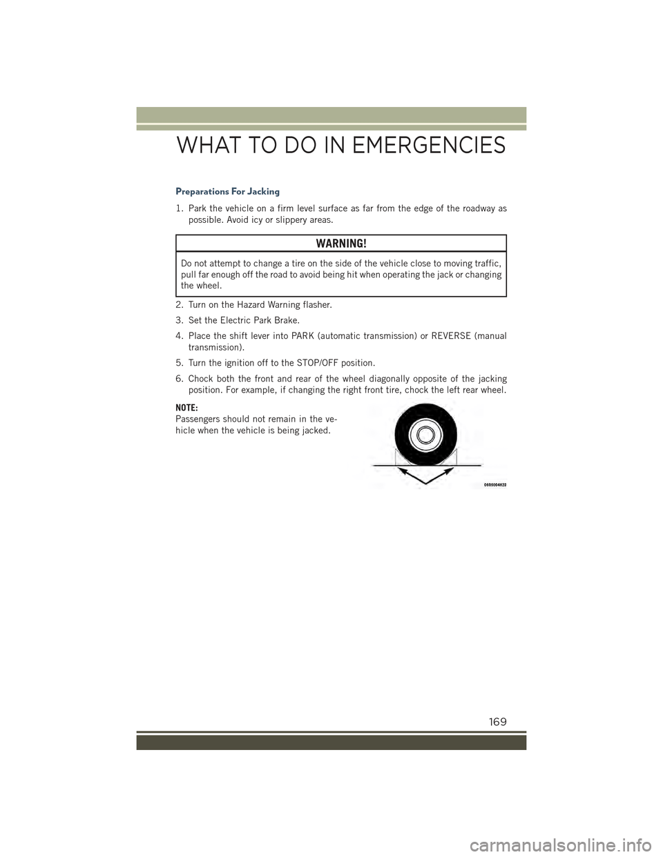
6. Chock both the front and rear of the wheel diagonally opposite of the jacking
position. For example, if changing the right front tire, chock the left rear wheel.
NOTE:
Passengers should not remain in the ve-
hicle when the vehicle is being jacked.
WHAT TO DO IN EMERGENCIES
169
Page 172 of 220
Jacking Instructions
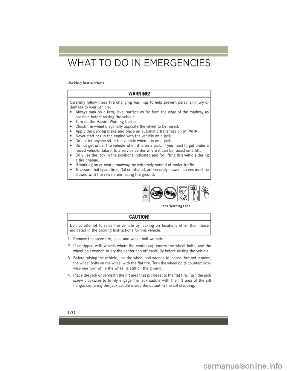
WARNING!
Carefully follow these tire changing warnings to help prevent personal injury or
damage to your vehicle:
• Always park on a firm, level surface as far from the edge of the roadway as
possible before raising the vehicle.
• Turn on the Hazard Warning flasher.
• Chock the wheel diagonally opposite the wheel to be raised.
• Apply the parking brake and place an automatic transmission in PARK.
• Never start or run the engine with the vehicle on a jack.
• Do not let anyone sit in the vehicle when it is on a jack.
• Do not get under the vehicle when it is on a jack. If you need to get under a
raised vehicle, take it to a service center where it can be raised on a lift.
• Only use the jack in the positions indicated and for lifting this vehicle during
a tire change.
• If working on or near a roadway, be extremely careful of motor traffic.
• To assure that spare tires, flat or inflated, are securely stowed, spares must be
stowed with the valve stem facing the ground.
CAUTION!
Do not attempt to raise the vehicle by jacking on locations other than those
indicated in the Jacking Instructions for this vehicle.
1. Remove the spare tire, jack, and wheel bolt wrench.
2. If equipped with wheels where the center cap covers the wheel bolts, use the
wheel bolt wrench to pry the center cap off carefully before raising the vehicle.
3. Before raising the vehicle, use the wheel bolt wrench to loosen, but not remove,
the wheel bolts on the wheel with the flat tire. Turn the wheel bolts counterclock-
wise one turn while the wheel is still on the ground.
4. Place the jack underneath the lift area that is closest to the flat tire. Turn the jack
screw clockwise to firmly engage the jack saddle with the lift area of the sill
flange, centering the jack saddle inside the cutout in the sill cladding.
Jack Warning Label
WHAT TO DO IN EMERGENCIES
170
Page 175 of 220
9. Lower the vehicle to the ground by turning the jack handle counterclockwise.
10. Finish tightening the wheel bolts. Push down on the wrench while at the end of
the handle for increased leverage. Tighten the wheel bolts in a star pattern until
each wheel bolt has been tightened twice. The correct torque specification for
the wheel bolts is 63 Ft-Lbs (86 Nm) for steel wheels and 89 Ft-Lbs (120 Nm)
for aluminum wheels. If in doubt about the correct tightness, have them
checked with a torque wrench by your authorized dealer or at a service station.
11. Securely stow the jack, tools, chocks and flat tire.
WARNING!
A loose tire or jack thrown forward in a collision or hard stop could endanger the
occupants of the vehicle. Always stow the jack parts and the spare tire in the
places provided. Have the deflated (flat) tire repaired or replaced immediately.
Road Tire Installation
1. Mount the road tire on the axle.
2. Install the remaining wheel bolts with the threaded end of the wheel bolt toward
the wheel. Lightly tighten the wheel bolts.
WARNING!
To avoid the risk of forcing the vehicle off the jack, do not tighten the lug nuts fully
until the vehicle has been lowered. Failure to follow this warning may result in
serious injury.
3. Lower the vehicle to the ground by turning the jack handle counterclockwise.
4. Finish tightening the wheel bolts. Push down on the wrench while at the end ofthe handle for increased leverage. Tighten the wheel bolts in a star pattern untileach wheel bolt has been tightened twice. The correct torque specification for thewheel bolts is 63 Ft-Lbs (86 Nm) for steel wheels and 89 Ft-Lbs (120 Nm) foraluminum wheels. If in doubt about the correct tightness, have them checkedwith a torque wrench by your authorized dealer or at a service station.
5. Lower the jack until it is free. Remove the wheel chocks. Stow the jack and tools
back in the proper storage location. Release the Electric Park Brake before driving
the vehicle.
6. After 25 miles (40 km) check the wheel bolt torque with a torque wrench to
ensure that all wheel bolts are properly seated against the wheel.
WHAT TO DO IN EMERGENCIES
173
Page 176 of 220
JUMP-STARTING PROCEDURES
If your vehicle has a discharged battery it can be jump-started using a set of jumper
cables and a battery in another vehicle or by using a portable battery booster pack.
Jump-starting can be dangerous if done improperly so please follow the procedures
in this section carefully.
NOTE:
When using a portable battery booster pack follow the manufacturer’s operating
instructions and precautions.
CAUTION!
Do not use a portable battery booster pack or any other booster source with a
system voltage greater than 12 Volts or damage to the battery, starter motor,
alternator or electrical system may occur.
WARNING!
Do not attempt jump-starting if the battery is frozen. It could rupture or explode
and cause personal injury.
Preparations For Jump-Start
The battery in your vehicle is located in the front of the engine compartment, behind
the left headlight assembly.
NOTE:
The positive battery post is covered with a protective cap. Lift up on the cap to gain
access to the positive battery post.
WARNING!
• Take care to avoid the radiator cooling fan whenever the hood is raised. It can
start anytime the ignition switch is ON. You can be injured by moving fan
blades.
• Remove any metal jewelry such as rings, watch bands and bracelets that could
make an inadvertent electrical contact. You could be seriously injured.
• Batteries contain sulfuric acid that can burn your skin or eyes and generate
hydrogen gas which is flammable and explosive. Keep open flames or sparks
away from the battery.
Proceed as follows:
1. Set the Electric Park Brake, shift the automatic transmission into PARK (manual
transmission in NEUTRAL) and turn the ignition to STOP/OFF.
2. Turn off the heater, radio, and all unnecessary electrical accessories.
WHAT TO DO IN EMERGENCIES
174
Page 177 of 220
3. If using another vehicle to jump-start the battery, park the vehicle within the
jumper cables reach, set the parking brake and make sure the ignition is
STOP/OFF.
WARNING!
Do not allow vehicles to touch each other as this could establish a ground
connection and personal injury could result.
Jump-Starting Procedure
WARNING!
Failure to follow this jump-starting procedure could result in personal injury or
property damage due to battery explosion.
CAUTION!
Failure to follow these procedures could result in damage to the charging system
of the booster vehicle or the discharged vehicle.
Connecting The Jumper Cables
1. Connect the positive(+)end of the jumper cable to the positive(+)post of the
discharged vehicle.
2. Connect the opposite end of the positive(+)jumper cable to the positive(+)post
of the booster battery.
3. Connect the negative(-)end of the jumper cable to the negative(-)post of the
booster battery.
4. Connect the opposite end of the negative(-)jumper cable to a good engine ground
(exposed metal part of the discharged vehicle’s engine) away from the battery and
the fuel injection system.
WARNING!
Do not connect the jumper cable to the negative (-) post of the discharged battery.
The resulting electrical spark could cause the battery to explode and could result
in serious injury. Only use the specific ground point, do not use any other exposed
metal parts.
5. Start the engine in the vehicle that has the booster battery, let the engine idle a
few minutes, and then start the engine in the vehicle with the discharged battery.
WHAT TO DO IN EMERGENCIES
175
Page 178 of 220
6. Once the engine is started, remove the jumper cables in the reverse sequence:
Disconnecting The Jumper Cables
1. Disconnect the negative(-)end of the jumper cable from the engine ground of the
vehicle with the discharged battery.
2. Disconnect the opposite end of the negative(-)jumper cable from the negative(-)
post of the booster battery.
3. Disconnect the positive(+)end of the jumper cable from the positive(+)post of
the booster battery.
4. Disconnect the opposite end of the positive(+)jumper cable from the positive(+)
post of the vehicle with the discharged battery.
If frequent jump-starting is required to start your vehicle you should have the battery
and charging system inspected at your authorized dealer.
CAUTION!
Accessories plugged into the vehicle power outlets draw power from the vehicle’s
battery, even when not in use (i.e., cellular phones, etc.). Eventually, if plugged in
long enough without engine operation, the vehicle’s battery will discharge suffi-
ciently to degrade battery life and/or prevent the engine from starting.
FREEING A STUCK VEHICLE
If your vehicle becomes stuck in mud, sand or snow, it can often be moved using a
rocking motion. Turn the steering wheel right and left to clear the area around the
front wheels. For vehicles with automatic transmission, push and hold the lock
button on the shift lever. Then shift back and forth between DRIVE and REVERSE
(with automatic transmission) or 2ND GEAR and REVERSE (with manual transmis-
sion), while gently pushing the accelerator.
For Vehicles With Automatic Transmission:
Shifts between DRIVE and REVERSE can only be achieved at wheel speeds of 5 mph
(8 km/h) or less. Whenever the transmission remains in NEUTRAL for more than two
seconds, you must push the brake pedal to engage DRIVE or REVERSE.
Use the least amount of accelerator pedal pressure that will maintain the rocking
motion without spinning the wheels or racing the engine.
WHAT TO DO IN EMERGENCIES
176
Page 179 of 220
CAUTION!
• Racing the engine or spinning the wheels may lead to transmission overheatingand failure. Allow the engine to idle with the transmission in NEUTRAL for atleast one minute after every five rocking-motion cycles. This will minimizeoverheating and reduce the risk of clutch or transmission failure duringprolonged efforts to free a stuck vehicle.
• When “rocking” a stuck vehicle by shifting between DRIVE/2nd gear and
REVERSE, do not spin the wheels faster than 15 mph (24 km/h), or drivetrain
damage may result.
• Revving the engine or spinning the wheels too fast may lead to transmission
overheating and failure. It can also damage the tires. Do not spin the wheels
above 30 mph (48 km/h) while in gear (no transmission shifting occurring).
WARNING!
Fast spinning tires can be dangerous. Forces generated by excessive wheel speeds
may cause damage, or even failure, of the axle and tires. A tire could explode and
injure someone. Do not spin your vehicle's wheels faster than 30 mph (48 km/h)
or for longer than 30 seconds continuously without stopping when you are stuck
and do not let anyone near a spinning wheel, no matter what the speed.
EMERGENCY TOW HOOKS
If your vehicle is equipped with tow hooks, there will be one in the rear and two
mounted on the front of the vehicle. The rear hook will be located on the driver's side
of the vehicle.
NOTE:
For off-road recovery, it is recommended to use both of the front tow hooks to
minimize the risk of damage to the vehicle.
Vehicles Equipped With RKE Transmitter With An Integrated Vehicle Key
Turn the ignition key to the MAR/RUN and then STOP/OFF position, without
removing it. By extracting the key this will automatically engage the steering wheel
lock. Place the transmission into NEUTRAL.
Vehicles With Keyless Enter-N-Go™
Place the ignition in the RUN and subsequently on STOP, without opening the door.
During towing remember that not having the aid of the power brakes and the
electromechanical power steering, greater force is needed in applying the brakes and
steering of the vehicle.
WHAT TO DO IN EMERGENCIES
177
Page 180 of 220
WARNING!
• Do not use a chain for freeing a stuck vehicle. Chains may break, causingserious injury or death.
• Stand clear of vehicles when pulling with tow hooks. Tow straps may becomedisengaged, causing serious injury.
CAUTION!
Tow hooks are for emergency use only, to rescue a vehicle stranded off road. Do not use
tow hooks for tow truck hookup or highway towing. You could damage your vehicle.
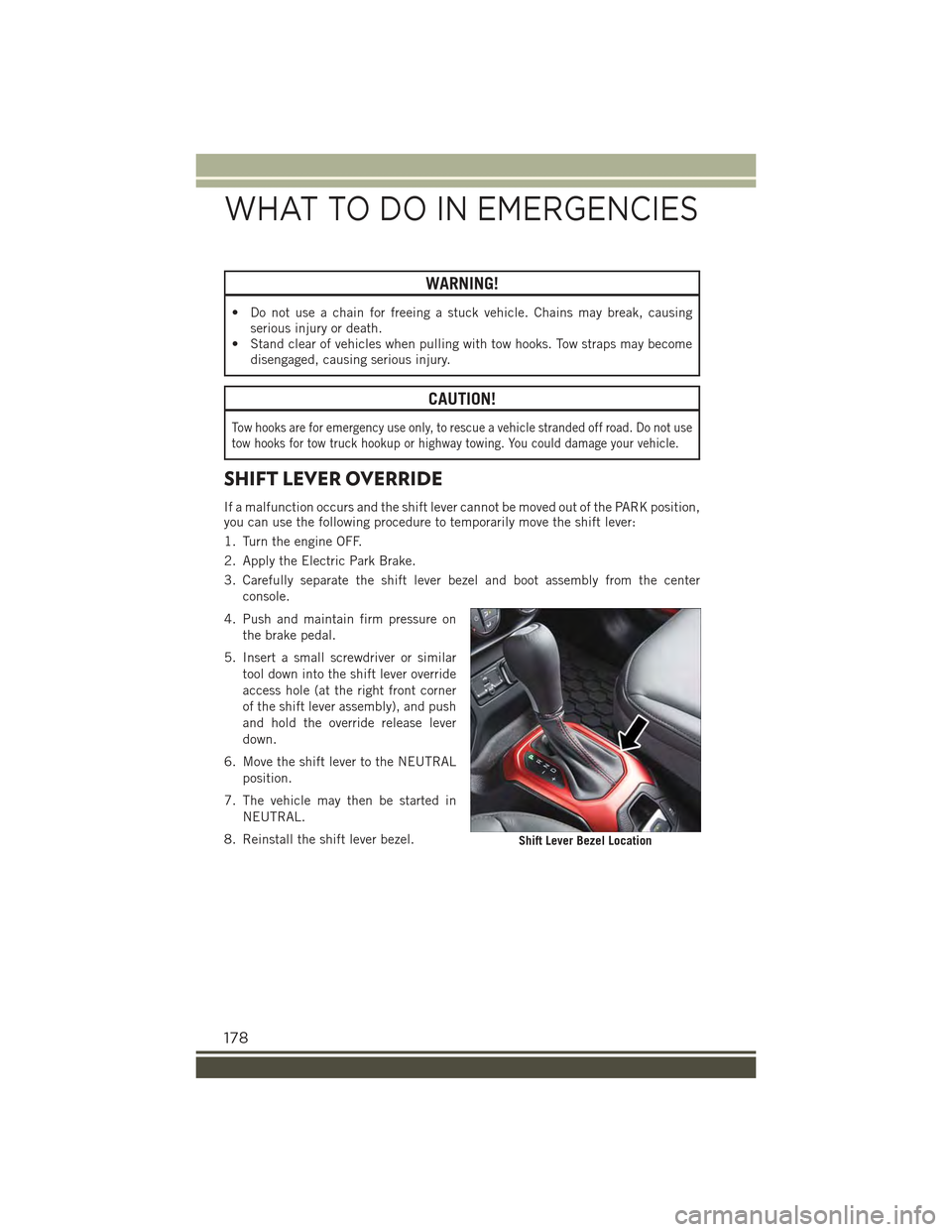
SHIFT LEVER OVERRIDE
If a malfunction occurs and the shift lever cannot be moved out of the PARK position,you can use the following procedure to temporarily move the shift lever:
1. Turn the engine OFF.
2. Apply the Electric Park Brake.
3. Carefully separate the shift lever bezel and boot assembly from the center
console.
4. Push and maintain firm pressure on
the brake pedal.
5. Insert a small screwdriver or similar
tool down into the shift lever override
access hole (at the right front corner
of the shift lever assembly), and push
and hold the override release lever
down.
6. Move the shift lever to the NEUTRAL
position.
7. The vehicle may then be started in
NEUTRAL.
8. Reinstall the shift lever bezel.Shift Lever Bezel Location
WHAT TO DO IN EMERGENCIES
178