steering JEEP RENEGADE 2015 1.G Owner's Guide
[x] Cancel search | Manufacturer: JEEP, Model Year: 2015, Model line: RENEGADE, Model: JEEP RENEGADE 2015 1.GPages: 220, PDF Size: 34.11 MB
Page 154 of 220
SELEC-TERRAIN™
Selec-Terrain™ combines the capabilities of the vehicle control systems, along with
driver input, to provide the best performance for all terrains.
Mode Selection Guide
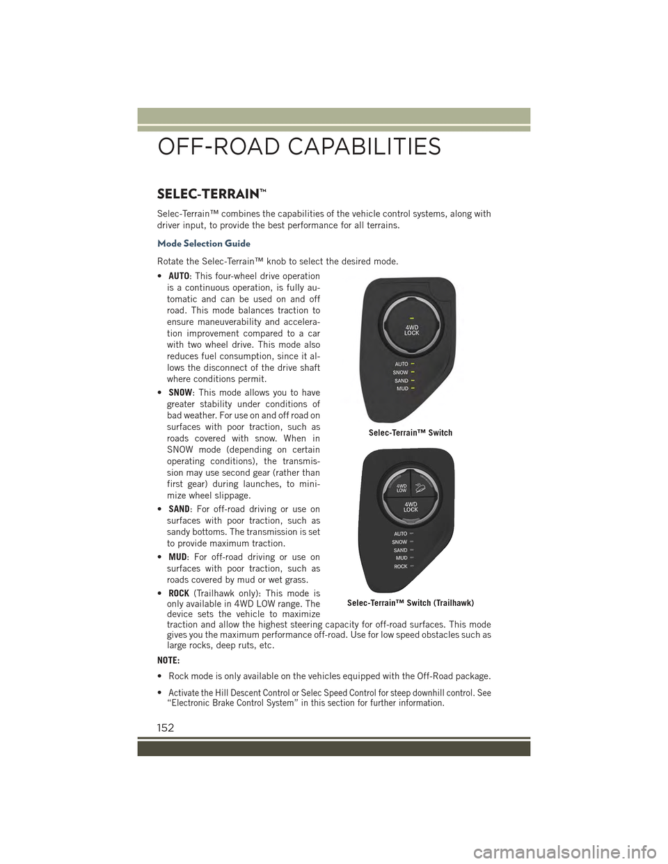
Rotate the Selec-Terrain™ knob to select the desired mode.
•AUTO: This four-wheel drive operation
is a continuous operation, is fully au-
tomatic and can be used on and off
road. This mode balances traction to
ensure maneuverability and accelera-
tion improvement compared to a car
with two wheel drive. This mode also
reduces fuel consumption, since it al-
lows the disconnect of the drive shaft
where conditions permit.
•SNOW: This mode allows you to have
greater stability under conditions of
bad weather. For use on and off road on
surfaces with poor traction, such as
roads covered with snow. When in
SNOW mode (depending on certain
operating conditions), the transmis-
sion may use second gear (rather than
first gear) during launches, to mini-
mize wheel slippage.
•SAND: For off-road driving or use on
surfaces with poor traction, such as
sandy bottoms. The transmission is set
to provide maximum traction.
•MUD: For off-road driving or use on
surfaces with poor traction, such as
roads covered by mud or wet grass.
•ROCK(Trailhawk only): This mode isonly available in 4WD LOW range. Thedevice sets the vehicle to maximizetraction and allow the highest steering capacity for off-road surfaces. This modegives you the maximum performance off-road. Use for low speed obstacles such aslarge rocks, deep ruts, etc.
NOTE:
• Rock mode is only available on the vehicles equipped with the Off-Road package.
•Activate the Hill Descent Control or Selec Speed Control for steep downhill control. See“Electronic Brake Control System” in this section for further information.
Selec-Terrain™ Switch
Selec-Terrain™ Switch (Trailhawk)
OFF-ROAD CAPABILITIES
152
Page 178 of 220
6. Once the engine is started, remove the jumper cables in the reverse sequence:
Disconnecting The Jumper Cables
1. Disconnect the negative(-)end of the jumper cable from the engine ground of the
vehicle with the discharged battery.
2. Disconnect the opposite end of the negative(-)jumper cable from the negative(-)
post of the booster battery.
3. Disconnect the positive(+)end of the jumper cable from the positive(+)post of
the booster battery.
4. Disconnect the opposite end of the positive(+)jumper cable from the positive(+)
post of the vehicle with the discharged battery.
If frequent jump-starting is required to start your vehicle you should have the battery
and charging system inspected at your authorized dealer.
CAUTION!
Accessories plugged into the vehicle power outlets draw power from the vehicle’s
battery, even when not in use (i.e., cellular phones, etc.). Eventually, if plugged in
long enough without engine operation, the vehicle’s battery will discharge suffi-
ciently to degrade battery life and/or prevent the engine from starting.
FREEING A STUCK VEHICLE
If your vehicle becomes stuck in mud, sand or snow, it can often be moved using a
rocking motion. Turn the steering wheel right and left to clear the area around the
front wheels. For vehicles with automatic transmission, push and hold the lock
button on the shift lever. Then shift back and forth between DRIVE and REVERSE
(with automatic transmission) or 2ND GEAR and REVERSE (with manual transmis-
sion), while gently pushing the accelerator.
For Vehicles With Automatic Transmission:
Shifts between DRIVE and REVERSE can only be achieved at wheel speeds of 5 mph
(8 km/h) or less. Whenever the transmission remains in NEUTRAL for more than two
seconds, you must push the brake pedal to engage DRIVE or REVERSE.
Use the least amount of accelerator pedal pressure that will maintain the rocking
motion without spinning the wheels or racing the engine.
WHAT TO DO IN EMERGENCIES
176
Page 179 of 220
CAUTION!
• Racing the engine or spinning the wheels may lead to transmission overheatingand failure. Allow the engine to idle with the transmission in NEUTRAL for atleast one minute after every five rocking-motion cycles. This will minimizeoverheating and reduce the risk of clutch or transmission failure duringprolonged efforts to free a stuck vehicle.
• When “rocking” a stuck vehicle by shifting between DRIVE/2nd gear and
REVERSE, do not spin the wheels faster than 15 mph (24 km/h), or drivetrain
damage may result.
• Revving the engine or spinning the wheels too fast may lead to transmission
overheating and failure. It can also damage the tires. Do not spin the wheels
above 30 mph (48 km/h) while in gear (no transmission shifting occurring).
WARNING!
Fast spinning tires can be dangerous. Forces generated by excessive wheel speeds
may cause damage, or even failure, of the axle and tires. A tire could explode and
injure someone. Do not spin your vehicle's wheels faster than 30 mph (48 km/h)
or for longer than 30 seconds continuously without stopping when you are stuck
and do not let anyone near a spinning wheel, no matter what the speed.
EMERGENCY TOW HOOKS
If your vehicle is equipped with tow hooks, there will be one in the rear and two
mounted on the front of the vehicle. The rear hook will be located on the driver's side
of the vehicle.
NOTE:
For off-road recovery, it is recommended to use both of the front tow hooks to
minimize the risk of damage to the vehicle.
Vehicles Equipped With RKE Transmitter With An Integrated Vehicle Key
Turn the ignition key to the MAR/RUN and then STOP/OFF position, without
removing it. By extracting the key this will automatically engage the steering wheel
lock. Place the transmission into NEUTRAL.
Vehicles With Keyless Enter-N-Go™
Place the ignition in the RUN and subsequently on STOP, without opening the door.
During towing remember that not having the aid of the power brakes and the
electromechanical power steering, greater force is needed in applying the brakes and
steering of the vehicle.
WHAT TO DO IN EMERGENCIES
177
Page 196 of 220
FUSES
WARNING!
• When replacing a blown fuse, always use an appropriate replacement fuse with
the same amp rating as the original fuse. Never replace a fuse with another
fuse of higher amp rating. Never replace a blown fuse with metal wires or any
other material. Failure to use proper fuses may result in serious personal injury,
fire and/or property damage.
• Before replacing a fuse, make sure that the ignition is off and that all the other
services are switched off and/or disengaged.
• If the replaced fuse blows again, contact an authorized dealer.
• If a general protection fuse for safety systems (air bag system, braking system),
power unit systems (engine system, gearbox system) or steering system blows,
contact an authorized dealer.
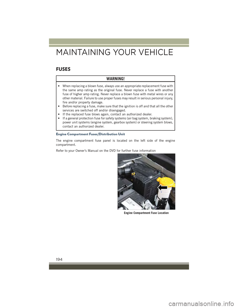
Engine Compartment Fuses/Distribution Unit
The engine compartment fuse panel is located on the left side of the engine
compartment.
Refer to your Owner’s Manual on the DVD for further fuse information
Engine Compartment Fuse Location
MAINTAINING YOUR VEHICLE
194
Page 199 of 220
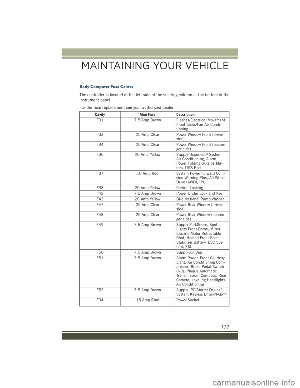
Body Computer Fuse Center
The controller is located at the left side of the steering column at the bottom of the
instrument panel.
For the fuse replacement see your authorized dealer.
CavityMini FuseDescription
F317.5 Amp Brown Flashes/Electrical MovementFront Seats/Fan Air Condi-tioning
F3325 Amp Clear Power Window Front (driverside)
F3425 Amp Clear Power Window Front (passen-ger side)
F3620 Amp Yellow Supply Uconnect®System,Air Conditioning, Alarm,Power Folding Outside Mir-rors, USB Port
F3710 Amp Red System Power Forward Colli-sion Warning Plus, All WheelDrive (AWD), IPC
F3820 Amp Yellow Central Locking
F427.5 Amp Brown Power Under Lock and Key
F4320 Amp Yellow Bi-directional Pump Washer
F4725 Amp Clear Power Rear Window (driverside)
F4825 Amp Clear Power Rear Window (passen-ger side)
F497.5 Amp Brown Supply ParkSense, SpotLights Front Dome, Mirror,Electric Motor RetractableRoof, Heated Front Seats,Stabilizer Battery, ESC Sys-tem, ESL
F507.5 Amp Brown Supply Air Bag
F517.5 Amp Brown Alarm Power, Front CourtesyLight, Air Conditioning Com-pressor, Brake Pedal Switch(NC), Plaque AutomaticTransmission, Compass, RearCamera, Leveling Headlights,Air Conditioning
F537.5 Amp Brown Supply IPC/Starter Device/System Keyless Enter-N-Go™
F9415 Amp Blue Power Socket
MAINTAINING YOUR VEHICLE
197
Page 202 of 220
WARNING!
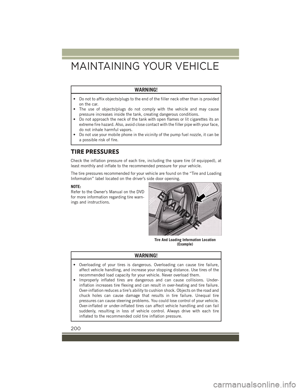
• Do not to affix objects/plugs to the end of the filler neck other than is provided
on the car.
• The use of objects/plugs do not comply with the vehicle and may cause
pressure increases inside the tank, creating dangerous conditions.
• Do not approach the neck of the tank with open flames or lit cigarettes its an
extreme fire hazard. Also, avoid close contact with the filler pipe with your face,
do not inhale harmful vapors.
• Do not use your mobile phone in the vicinity of the pump fuel nozzle, it can be
a possible risk of fire.
TIRE PRESSURES
Check the inflation pressure of each tire, including the spare tire (if equipped), at
least monthly and inflate to the recommended pressure for your vehicle.
The tire pressures recommended for your vehicle are found on the “Tire and Loading
Information” label located on the driver’s side door opening.
NOTE:
Refer to the Owner's Manual on the DVD
for more information regarding tire warn-
ings and instructions.
WARNING!
• Overloading of your tires is dangerous. Overloading can cause tire failure,
affect vehicle handling, and increase your stopping distance. Use tires of the
recommended load capacity for your vehicle. Never overload them.
• Improperly inflated tires are dangerous and can cause collisions. Under-
inflation increases tire flexing and can result in over-heating and tire failure.
Over-inflation reduces a tire’s ability to cushion shock. Objects on the road and
chuck holes can cause damage that results in tire failure. Unequal tire
pressures can cause steering problems. You could lose control of your vehicle.
Over-inflated or under-inflated tires can affect vehicle handling and can fail
suddenly, resulting in loss of vehicle control. Always drive with each tire
inflated to the recommended cold tire inflation pressure.
Tire And Loading Information Location(Example)
MAINTAINING YOUR VEHICLE
200
Page 213 of 220
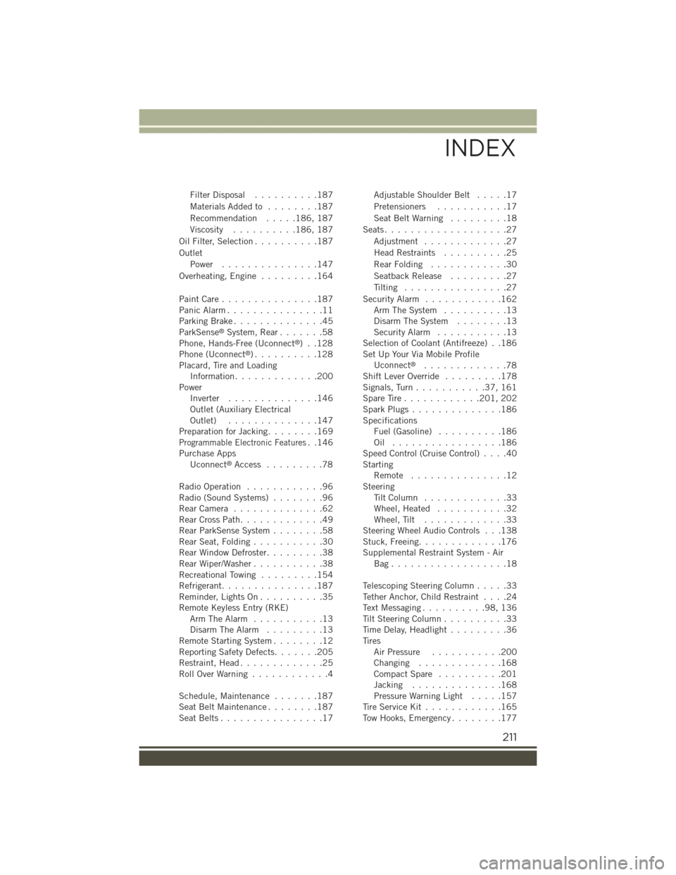
Filter Disposal..........187
Materials Added to........187
Recommendation.....186, 187
Viscosity..........186, 187
Oil Filter, Selection..........187
Outlet
Power...............147
Overheating, Engine.........164
Paint Care . . . . . . . . . . . . . . .187Panic Alarm...............11Parking Brake..............45ParkSense®System, Rear.......58Phone, Hands-Free (Uconnect®)..128Phone (Uconnect®). . . . . . . . . .128Placard, Tire and LoadingInformation.............200PowerInverter..............146Outlet (Auxiliary ElectricalOutlet)..............147Preparation for Jacking........169Programmable Electronic Features..146Purchase AppsUconnect®Access.........78
Radio Operation............96Radio (Sound Systems)........96Rear Camera . . . . . . . . . . . . . .62Rear Cross Path.............49Rear ParkSense System........58Rear Seat, Folding...........30Rear Window Defroster.........38Rear Wiper/Washer...........38Recreational Towing.........154Refrigerant...............187Reminder, Lights On . . . . . . . . . .35Remote Keyless Entry (RKE)Arm The Alarm...........13Disarm The Alarm.........13Remote Starting System........12Reporting Safety Defects.......205Restraint, Head.............25Roll Over Warning . . . . . . . . . . . .4
Schedule, Maintenance.......187Seat Belt Maintenance . . . . . . . .187Seat Belts................17
Adjustable Shoulder Belt.....17
Pretensioners...........17
Seat Belt Warning . . . . . . . . .18
Seats...................27
Adjustment . . . . . . . . . . . . .27
Head Restraints..........25
Rear Folding............30
Seatback Release.........27
Tilting................27
Security Alarm............162Arm The System..........13Disarm The System........13Security Alarm...........13Selection of Coolant (Antifreeze) . .186Set Up Your Via Mobile ProfileUconnect®.............78Shift Lever Override.........178Signals, Turn...........37,161Spare Tire . . . . . . . . . . . .201, 202Spark Plugs . . . . . . . . . . . . . .186SpecificationsFuel (Gasoline)..........186Oil . . . . . . . . . . . . . . . . .186Speed Control (Cruise Control)....40StartingRemote . . . . . . . . . . . . . . .12SteeringTi l t C o l u m n . . . . . . . . . . . . . 3 3Wheel, Heated...........32Wheel, Tilt.............33Steering Wheel Audio Controls . . .138Stuck, Freeing.............176Supplemental Restraint System - AirBag . . . . . . . . . . . . . . . . . .18
Telescoping Steering Column.....33Tether Anchor, Child Restraint....24Text Messaging..........98,136Tilt Steering Column..........33Time Delay, Headlight.........36TiresAir Pressure...........200Changing . . . . . . . . . . . . .168Compact Spare..........201Jacking..............168Pressure Warning Light.....157Tire Service Kit............165Tow Hooks, Emergency........177
INDEX
211