air condition JEEP RENEGADE 2015 1.G User Guide
[x] Cancel search | Manufacturer: JEEP, Model Year: 2015, Model line: RENEGADE, Model: JEEP RENEGADE 2015 1.GPages: 220, PDF Size: 34.11 MB
Page 21 of 220
Advanced Front Air Bags
• This vehicle has Advanced Front Air Bags for both the driver and front passenger
as a supplement to the seat belt restraint systems. The Advanced Front Air Bags
will not deploy in every type of collision.
• Advanced Front Air Bags are designed to provide additional protection by
supplementing the seat belts. Advanced Front Air Bags are not expected to reduce
the risk of injury in rear, side, or rollover collisions.
• The Advanced Front Air Bags will not deploy in all frontal collisions, including
some that may produce substantial vehicle damage — for example, some pole
collisions, truck underrides, and angle offset collisions.
• On the other hand, depending on the type and location of impact, Advanced Front
Air Bags may deploy in crashes with little vehicle front-end damage but that
produce a severe initial deceleration.
• Because air bag sensors measure vehicle deceleration over time, vehicle speed
and damage by themselves are not good indicators of whether or not an air bag
should have deployed.
• Seat belts are necessary for your protection in all collisions, and also are needed
to help keep you in position, away from an inflating air bag.
• The air bags must be ready to inflate for your protection in a collision. The
Occupant Restraint Controller (ORC) monitors the internal circuits and intercon-
necting wiring associated with air bag system electrical components.
• The ORC turns on the Air Bag Warning Light in the instrument panel for
approximately four to eight seconds for a self-check when the ignition switch is
first turned to the ON/RUN position. After the self-check, the Air Bag Warning
Light will turn off. If the ORC detects a malfunction in any part of the system, it
turns on the Air Bag Warning Light, either momentarily or continuously. A single
chime will sound to alert you if the light comes on again after initial startup.
• The ORC monitors the readiness of the electronic parts of the air bag system
whenever the ignition switch is in the START or ON/RUN position. If the ignition
switch is in the OFF position or in the ACC position, the air bag system is not on
and the air bags will not inflate.
• If the Air Bag Warning Light in the instrument panel is not on during the four to
eight seconds when the ignition switch is first turned to the ON/RUN position,
stays on, or turns on while driving, have the vehicle serviced by an authorized
service center immediately.
NOTE:
If the speedometer, tachometer, or any engine related gauges are not working, the
Occupant Restraint Controller (ORC) may also be disabled. In this condition the air
bags may not be ready to inflate for your protection. Have an authorized dealer
service the air bag system immediately.
• After any collision, the vehicle should be taken to an authorized dealer immedi-
ately.
GETTING STARTED
19
Page 84 of 220
Built-In Features (Uconnect® 6.5A/6.5AN)
CAUTION!
• Ignoring the light/LED on the 9-1-1 button in the overhead console could meanyou may not have 9-1-1 Call service if needed. If the light/LED on the 9-1-1button in the overhead console is illuminated, have an authorized dealerservice the 9-1-1 Call system immediately.
• The Occupant Restraint Controller (ORC) turns on the Air Bag Warning Light onthe instrument panel if a malfunction is detected in any part of the air bagsystem. If the Air Bag Warning Light is illuminated, the air bag system may notbe working properly and the 9-1-1 system may not be able to send a signal toa 9-1-1 operator. If the Air Bag Warning Light is illuminated, have anauthorized dealer service your vehicle immediately.
• If anyone in the vehicle could be in danger (e.g., fire or smoke is visible,dangerous road conditions or location), do not wait for voice contact from a9-1-1 operator. All occupants should exit the vehicle immediately and move toa safe location.
• Do not add any aftermarket electrical equipment to the vehicle’s electricalsystem. This may prevent your vehicle from sending a signal to initiate anemergency call. To avoid interference that can cause the 9-1-1 Call system tofail, never add aftermarket equipment (e.g., two-way mobile radio, CB radio,data recorder, etc.) to your vehicle’s electrical system or modify the antennason your vehicle. IF YOUR VEHICLE LOSES BATTERY POWER FOR ANYREASON (INCLUDING DURING OR AFTER AN ACCIDENT), THEUCONNECT®FEATURES, APPS AND SERVICES, AMONG OTHERS, WILLNOT OPERATE.
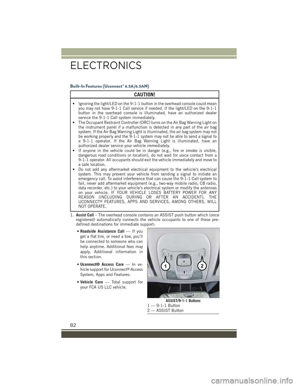
1.Assist Call– The overhead console contains an ASSIST push button which (onceregistered) automatically connects the vehicle occupants to one of these pre-defined destinations for immediate support:
•Roadside Assistance Call—Ifyou
get a flat tire, or need a tow, you’ll
be connected to someone who can
help anytime. Additional fees may
apply. Additional information in
this section.
•Uconnect® Access Care—Inve-
hicle support for Uconnect®Access
System, Apps and Features.
•Vehicle Care— Total support for
your FCA US LLC vehicle.
ASSIST/9-1-1 Buttons1 — 9-1-1 Button2 — ASSIST Button
ELECTRONICS
82
Page 160 of 220
IF THE LIGHT STARTS FLASHING INDICATING A LOW TIRE PRESSURE, ADJUST THE AIR
PRESSURE IN THE LOW TIRE TO THE AIR PRESSURE SHOWN ON THE VEHICLE PLACARD OR
TIRE INFLATION PRESSURE LABEL LOCATED ON THE DRIVER'S DOOR.
NOTE:
After inflation, the vehicle may need to be driven for 20 minutes before the flashing light
will turn off.
Please note that the TPMS is not a substitute for proper tire maintenance, and it is
the driver’s responsibility to maintain correct tire pressure, even if under-inflation has
not reached the level to trigger illumination of the TPMS low EVIC or DID display.
Your vehicle has also been equipped with a TPMS malfunction indicator to indicate
when the system is not operating properly. The TPMS malfunction indicator is
combined with the low tire pressure telltale. When the system detects a malfunction,
the telltale will flash for approximately one minute and then remain continuously
illuminated. This sequence will continue each time the vehicle is restarted as long as
the malfunction exists.
When the malfunction indicator is illuminated, the system may not be able to detect
or signal low tire pressure as intended. TPMS malfunctions may occur for a variety of
reasons, including the installation of replacement or alternate tires or wheels on the
vehicle that prevent the TPMS from functioning properly. Always check the TPMS
malfunction telltale after replacing one or more tires or wheels on your vehicle, to
ensure that the replacement or alternate tires and wheels allow the TPMS to continue
to function properly.
NOTE:
Tire pressures change by approximately 1 psi (7 kPa) per 12° F (7° C) of air
temperature change. Keep this in mind when checking tire pressure inside a garage,
especially in the Winter. Example: If garage temperature is 68°F (20°C) and the
outside temperature is 32°F (0°C), then the cold tire inflation pressure should be
increased by 3 psi (21 kPa), which equals 1 psi (7 kPa) for every 12°F (7°C) for this
outside temperature condition.
CAUTION!
The TPMS has been optimized for the original equipment tires and wheels. TPMS
pressures and warning have been established for the tire size equipped on your
vehicle. Undesirable system operation or sensor damage may result when using
replacement equipment that is not of the same size, type, and/or style. Aftermar-
ket wheels can cause sensor damage. Do not use tire sealant from a can, or
balance beads if your vehicle is equipped with a TPMS, as damage to the sensors
may result.
WHAT TO DO IN EMERGENCIES
158
Page 162 of 220
- Brake Warning Light
This light monitors various brake functions, including brake fluid level and parking
brake application. If the brake light turns on, it may indicate that the parking brake
is applied, that the brake fluid level is low, or that there is a problem with the
anti-lock brake system reservoir.
If the light remains on when the parking brake has been disengaged, and the fluid
level is at the full mark on the master cylinder reservoir, it indicates a possible brake
hydraulic system malfunction or that a problem with the Brake Booster has been
detected by the Anti-Lock Brake System (ABS)/Electronic Stability Control (ESC)
system. In this case, the light will remain on until the condition has been corrected.
If the problem is related to the brake booster, the ABS pump will run when applying
the brake, and a brake pedal pulsation may be felt during each stop.
The dual brake system provides a reserve braking capacity in the event of a failure to
a portion of the hydraulic system. A leak in either half of the dual brake system is
indicated by the Brake Warning Light, which will turn on when the brake fluid level
in the master cylinder has dropped below a specified level. The light will remain on
until the cause is corrected.
Vehicles equipped with the Anti-Lock Brake System (ABS) are also equipped with
Electronic Brake Force Distribution (EBD). In the event of an EBD failure, the Brake
Warning Light will turn on along with the ABS Light. Immediate repair to the ABS
system is required.
Operation of the Brake Warning Light can be checked by turning the ignition switch
from the STOP/OFF position to the MAR/RUN position. The light should illuminate
for approximately two seconds. The light should then turn off unless the parking
brake is applied or a brake fault is detected. If the light does not illuminate, have the
light inspected by an authorized dealer.
The light also will turn on when the parking brake is applied with the ignition switch
in the MAR/RUN position.
NOTE:
This light shows only that the parking brake is applied. It does not show the degree
of brake application.
WARNING!
Driving a vehicle with the red brake light on is dangerous. Part of the brake system
may have failed. It will take longer to stop the vehicle. You could have a collision.
Have the vehicle checked immediately.
WHAT TO DO IN EMERGENCIES
160
Page 166 of 220
IF YOUR ENGINE OVERHEATS
In any of the following situations, you can reduce the potential for overheating your
engine by taking the appropriate action.
• On the highways — slow down.
• In city traffic — while stopped, put transmission in NEUTRAL, but do not increase
engine idle speed.
CAUTION!
Driving with a hot cooling system could damage your vehicle. If the temperature
gauge reads “H,” pull over and stop the vehicle. Idle the vehicle with the air
conditioner turned off until the pointer drops back into the normal range. If the
pointer remains on the “H” and you hear continuous chimes, turn the engine off
immediately and call for service.
NOTE:
There are steps that you can take to slow down an impending overheat condition:
• If your air conditioner (A/C) is on, turn it off. The A/C system adds heat to the
engine cooling system and turning the A/C off can help remove this heat.
• You can also turn the temperature control to maximum heat, the mode control to
floor and the blower control to high. This allows the heater core to act as a
supplement to the radiator and aids in removing heat from the engine cooling
system.
WARNING!
You or others can be badly burned by hot engine coolant (antifreeze) or steam from
your radiator. If you see or hear steam coming from under the hood, do not open
the hood until the radiator has had time to cool. Never try to open a cooling system
pressure cap when the radiator or coolant bottle is hot.
WHAT TO DO IN EMERGENCIES
164
Page 167 of 220
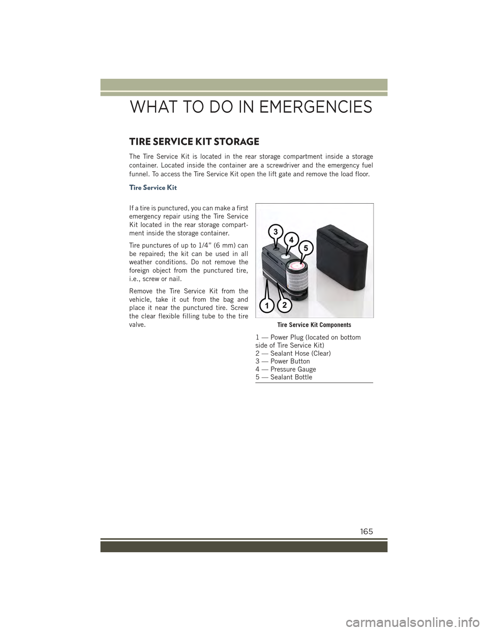
TIRE SERVICE KIT STORAGE
The Tire Service Kit is located in the rear storage compartment inside a storage
container. Located inside the container are a screwdriver and the emergency fuel
funnel. To access the Tire Service Kit open the lift gate and remove the load floor.
Tire Service Kit
If a tire is punctured, you can make a first
emergency repair using the Tire Service
Kit located in the rear storage compart-
ment inside the storage container.
Tire punctures of up to 1/4” (6 mm) can
be repaired; the kit can be used in all
weather conditions. Do not remove the
foreign object from the punctured tire,
i.e., screw or nail.
Remove the Tire Service Kit from the
vehicle, take it out from the bag and
place it near the punctured tire. Screw
the clear flexible filling tube to the tire
valve.Tire Service Kit Components
1 — Power Plug (located on bottomside of Tire Service Kit)2 — Sealant Hose (Clear)3 — Power Button4 — Pressure Gauge5 — Sealant Bottle
WHAT TO DO IN EMERGENCIES
165
Page 168 of 220
WARNING!
• Do not attempt to seal a tire on the side of the vehicle closest to traffic. Pull far
enough off the road to avoid the danger of being hit when using the Tire Service
Kit.
• Do not use Tire Service Kit or drive the vehicle under the following circum-
stances:
• If the puncture in the tire tread is approximately 1/4” (6 mm) or larger.
• If the tire has any sidewall damage.
• If the tire has any damage from driving with extremely low tire pressure.
• If the tire has any damage from driving on a flat tire.
• If the wheel has any damage.
• If you are unsure of the condition of the tire or the wheel.
• Keep Tire Service Kit away from open flames or heat source.
• A loose Tire Service Kit thrown forward in a collision or hard stop could
endanger the occupants of the vehicle. Always stow the Tire Service Kit in the
place provided. Failure to follow these warnings can result in injuries that are
serious or fatal to you, your passengers, and others around you.
• Take care not to allow the contents of Tire Service Kit to come in contact with
hair, eyes, or clothing. Tire Service Kit sealant is harmful if inhaled, swallowed,
or absorbed through the skin. It causes skin, eye, and respiratory irritation.
Flush immediately with plenty of water if there is any contact with eyes or skin.
Change clothing as soon as possible, if there is any contact with clothing.
• Tire Service Kit Sealant solution contains latex. In case of an allergic reaction
or rash, consult a physician immediately. Keep Tire Service Kit out of reach of
children. If swallowed, rinse mouth immediately with plenty of water and drink
plenty of water. Do not induce vomiting! Consult a physician immediately.
Insert the power plug into the vehicle power outlet socket. Start the vehicle engine.
Push the Tire Service Kit power button to the “I” position. The electric compressor
will be turned on, sealant and air will inflate the tire.
Minimum 26 psi (1.8 bar) of pressure should be reached within 20 minutes. If the
pressure has not been reached turn off and remove the Tire Service Kit, drive the
vehicle 30 feet (10 meters) back and forth, to better distribute the sealant inside the
tire.
Attach the clear flexible filling tube of the compressor directly to the tire valve and
repeat the inflation process.
When the correct pressure has been reached, start driving the vehicle to uniformly
distribute the sealant inside the tire. After 10 minutes, stop and check the tire
pressure. If the pressure is below 19 psi (1.3 bar), do not drive the vehicle, as the tire
is too damaged, contact the nearest Authorized Dealer.
WHAT TO DO IN EMERGENCIES
166
Page 190 of 220
Your authorized dealer will reset the oil change indicator message after completing
the scheduled oil change. If a scheduled oil change is performed by someone other
than your authorized dealer, the message can be reset by referring to the steps
described under “Electronic Vehicle Information Center (EVIC)/Driver Information
Display (DID)” in “Getting To Know Your Instrument Panel” in your Owners Manual
on the DVD for further information.
NOTE:
Under no circumstances should oil change intervals exceed 10,000 miles
(16,000 km) or one year, whichever comes first.
Severe Duty All Models
Change Engine Oil at 4000 miles (6,500 km) if the vehicle is operated in a dusty and
off road environment. This type of vehicle use is considered Severe Duty
NOTE:
The Oil Change Indicator will not illuminate under these conditions.
Once A Month Or Before A Long Trip:
• Check engine oil level.
• Check windshield washer fluid level.
• Check the tire inflation pressures and look for unusual wear or damage.
• Check the fluid levels of the coolant reservoir, and brake master cylinder reservoir,
and fill as needed.
• Check function of all interior and exterior lights.
Required Maintenance Intervals.
At Every Oil Change Interval As Indicated By Oil Change Indicator System:
Change oil and filter.
Inspect battery and clean and tighten terminals as required.
Inspect brake pads, shoes, rotors, drums, and hoses.
Inspect engine cooling system protection and hoses.
Check and adjust hand brake.
Inspect exhaust system.
Inspect engine air filter if using in dusty or off-road conditions.
Refer to the “Maintenance Chart” on the following page for the required maintenance
intervals.
MAINTAINING YOUR VEHICLE
188
Page 198 of 220
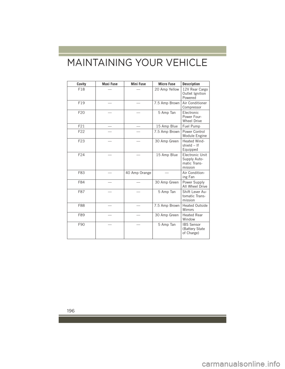
Cavity Maxi Fuse Mini Fuse Micro Fuse Description
F18——20AmpYellow12VRearCargoOutlet IgnitionPowered
F19——7.5AmpBrownAirConditionerCompressor
F20—— 5 Amp Tan ElectronicPower Four-Wheel Drive
F21——15AmpBlueFuelPump
F22——7.5AmpBrownPowerControlModule Engine
F23——30AmpGreenHeatedWind-shield – IfEquipped
F24——15AmpBlueElectronicUnitSupply Auto-matic Trans-mission
F83—40AmpOrange—AirCondition-ing Fan
F84——30AmpGreenPowerSupplyAll Wheel Drive
F87——5AmpTanShiftLeverAu-tomatic Trans-mission
F88——7.5AmpBrownHeatedOutsideMirrors
F89——30AmpGreenHeatedRearWindow
F90——5AmpTanIBSSensor(Battery Stateof Charge)
MAINTAINING YOUR VEHICLE
196
Page 199 of 220
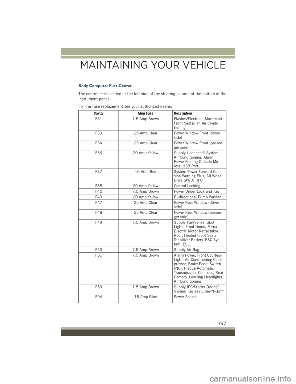
Body Computer Fuse Center
The controller is located at the left side of the steering column at the bottom of the
instrument panel.
For the fuse replacement see your authorized dealer.
CavityMini FuseDescription
F317.5 Amp Brown Flashes/Electrical MovementFront Seats/Fan Air Condi-tioning
F3325 Amp Clear Power Window Front (driverside)
F3425 Amp Clear Power Window Front (passen-ger side)
F3620 Amp Yellow Supply Uconnect®System,Air Conditioning, Alarm,Power Folding Outside Mir-rors, USB Port
F3710 Amp Red System Power Forward Colli-sion Warning Plus, All WheelDrive (AWD), IPC
F3820 Amp Yellow Central Locking
F427.5 Amp Brown Power Under Lock and Key
F4320 Amp Yellow Bi-directional Pump Washer
F4725 Amp Clear Power Rear Window (driverside)
F4825 Amp Clear Power Rear Window (passen-ger side)
F497.5 Amp Brown Supply ParkSense, SpotLights Front Dome, Mirror,Electric Motor RetractableRoof, Heated Front Seats,Stabilizer Battery, ESC Sys-tem, ESL
F507.5 Amp Brown Supply Air Bag
F517.5 Amp Brown Alarm Power, Front CourtesyLight, Air Conditioning Com-pressor, Brake Pedal Switch(NC), Plaque AutomaticTransmission, Compass, RearCamera, Leveling Headlights,Air Conditioning
F537.5 Amp Brown Supply IPC/Starter Device/System Keyless Enter-N-Go™
F9415 Amp Blue Power Socket
MAINTAINING YOUR VEHICLE
197