radio JEEP RENEGADE 2017 1.G Owners Manual
[x] Cancel search | Manufacturer: JEEP, Model Year: 2017, Model line: RENEGADE, Model: JEEP RENEGADE 2017 1.GPages: 516, PDF Size: 5.73 MB
Page 15 of 516
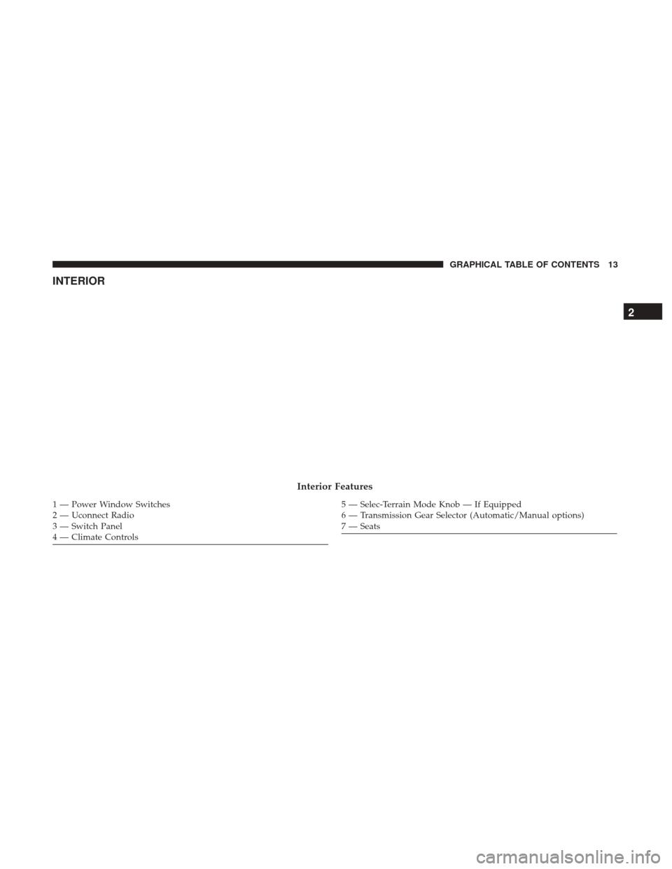
INTERIOR
Interior Features
1 — Power Window Switches
2 — Uconnect Radio
3 — Switch Panel
4 — Climate Controls5 — Selec-Terrain Mode Knob — If Equipped
6 — Transmission Gear Selector (Automatic/Manual options)
7 — Seats
2
GRAPHICAL TABLE OF CONTENTS 13
Page 23 of 516
Vehicles Equipped With Keyless Enter-N-Go — Passive
Entry
If one or more doors are open, or the liftgate is open, the
doors will lock. The doors will unlock again automatically
if the key is left inside the passenger compartment, other-
wise the doors will stay locked.
Programming Additional Key Fobs
Programming the key fob may be performed by an autho-
rized dealer.
Request For Additional Key Fobs
NOTE:Only key fobs that are programmed to the vehicle
electronics can be used to start and operate the vehicle.
Once a key fob is programmed to a vehicle, it cannot be
programmed to any other vehicle.
WARNING!
• Always remove the key fobs from the vehicle and
lock all doors when leaving the vehicle unattended.
• Always remember to place the ignition in the OFF
mode. Duplication of key fobs may be performed at an authorized
dealer. This procedure consists of programming a blank
key fob to the vehicle electronics. A blank key fob is one
that has never been programmed.
NOTE:
When having the Sentry Key Immobilizer System
serviced, bring all vehicle keys with you to an authorized
dealer.
General Information
The following regulatory statement applies to all Radio
Frequency (RF) devices equipped in this vehicle:
This device complies with Part 15 of the FCC Rules and
with Industry Canada license-exempt RSS standard(s).
Operation is subject to the following two conditions:
1. This device may not cause harmful interference.
2. This device must accept any interference received, in- cluding interference that may cause undesired opera-
tion.
NOTE: Changes or modifications not expressly approved
by the party responsible for compliance could void the
user ’s authority to operate the equipment.
3
GETTING TO KNOW YOUR VEHICLE 21
Page 28 of 516
the door handles, and disarm the Vehicle Security Alarm (if
equipped). Then, prior to the end of the 15-minute cycle,
push and release the START/STOP button.
NOTE:For vehicles equipped with the Keyless Enter-
N-Go — Passive Entry feature, the message “Remote Start
Active — Push Start Button” will display in the instrument
cluster display until you push the ignition START button.
Remote Start Comfort Systems — If Equipped
When Remote Start is activated, the heated steering wheel
and driver heated seat features will automatically turn on
in cold weather. These features will stay on through the
duration of Remote Start or until the ignition switch is
cycled to the RUN position.
NOTE: The Remote Start Comfort System can be activated
and deactivated through the Uconnect Settings. For more
information on Remote Start Comfort System operation,
refer to “Uconnect Settings” in “Multimedia.”
Remote Start Windshield Wiper De–Icer Activation
— If Equipped
When remote start is active and the outside ambient
temperature is less than 40°F (4.4°C), the Windshield Wiper
De-Icer will be enabled. Exiting remote start will resume previous operation, except if the Windshield Wiper De-Icer
is active. The Windshield Wiper De-Icer timer and opera-
tion will continue.
General Information
The following regulatory statement applies to all Radio
Frequency (RF) devices equipped in this vehicle:
This device complies with Part 15 of the FCC Rules and
with Industry Canada license-exempt RSS standard(s).
Operation is subject to the following two conditions:
1. This device may not cause harmful interference, and
2. This device must accept any interference received, in-
cluding interference that may cause undesired opera-
tion.
NOTE: Changes or modifications not expressly approved
by the party responsible for compliance could void the
user ’s authority to operate the equipment.
SENTRY KEY
The Sentry Key Immobilizer system prevents unauthorized
vehicle operation by disabling the engine. The system does
not need to be armed or activated. Operation is automatic,
regardless of whether the vehicle is locked or unlocked.
26 GETTING TO KNOW YOUR VEHICLE
Page 30 of 516
CAUTION!(Continued)
•For vehicles equipped with Keyless Enter-N-Go —
Ignition, always remember to place the ignition in
the OFF position.
NOTE: Duplication of key fobs may be performed at an
authorized dealer. This procedure consists of programming
a blank key fob to the vehicle electronics. A blank key fob
is one that has never been programmed.
When having the Sentry Key Immobilizer System serviced,
bring all vehicle keys with you to an authorized dealer.
General Information
The following regulatory statement applies to all radio
frequency (RF) devices equipped in this vehicle:
This device complies with Part 15 of the FCC Rules and
with Industry Canada license-exempt RSS standard(s).
Operation is subject to the following two conditions:
1. This device may not cause harmful interference, and
2. This device must accept any interference received, in- cluding interference that may cause undesired opera-
tion. NOTE:
Changes or modifications not expressly approved
by the party responsible for compliance could void the
user ’s authority to operate the equipment.
VEHICLE SECURITY ALARM — IF EQUIPPED
The vehicle security alarm monitors the vehicle doors,
hood, liftgate, and the Keyless Enter-N-Go — Ignition for
unauthorized operation. While the vehicle security alarm is
armed, interior switches for door locks and liftgate release
are disabled. If something triggers the alarm, the vehicle
security alarm will provide the following audible and
visible signals:
• The horn will pulse
• The turn signals will flash
• The vehicle security light in the instrument cluster will
flash
To Arm The System
Follow these steps to arm the vehicle security alarm:
1. Make sure the vehicle’s ignition is placed in the “OFF” mode.
2. Perform one of the following methods to lock the vehicle:
28 GETTING TO KNOW YOUR VEHICLE
Page 50 of 516
STEERING WHEEL
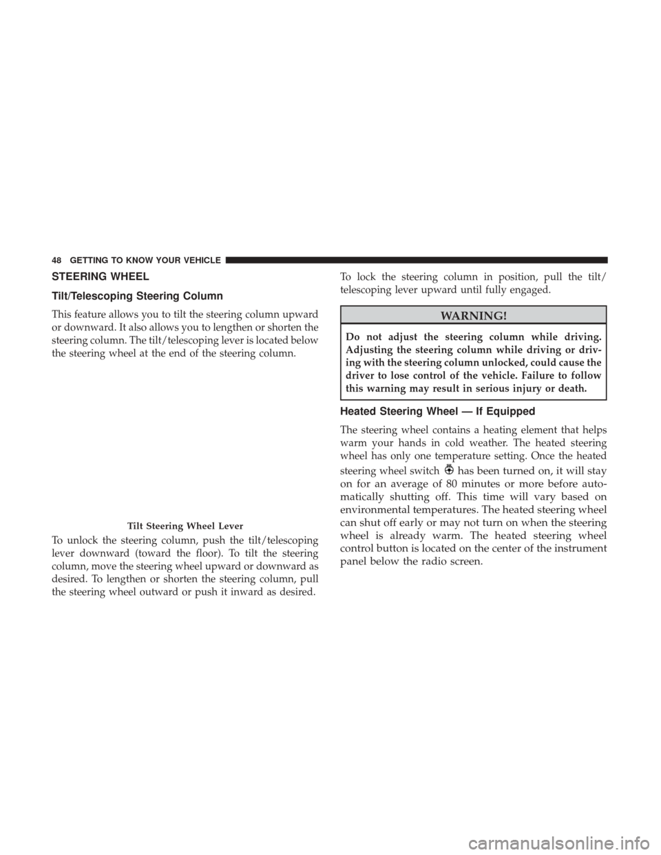
Tilt/Telescoping Steering Column
This feature allows you to tilt the steering column upward
or downward. It also allows you to lengthen or shorten the
steering column. The tilt/telescoping lever is located below
the steering wheel at the end of the steering column.
To unlock the steering column, push the tilt/telescoping
lever downward (toward the floor). To tilt the steering
column, move the steering wheel upward or downward as
desired. To lengthen or shorten the steering column, pull
the steering wheel outward or push it inward as desired.To lock the steering column in position, pull the tilt/
telescoping lever upward until fully engaged.WARNING!
Do not adjust the steering column while driving.
Adjusting the steering column while driving or driv-
ing with the steering column unlocked, could cause the
driver to lose control of the vehicle. Failure to follow
this warning may result in serious injury or death.
Heated Steering Wheel — If Equipped
The steering wheel contains a heating element that helps
warm your hands in cold weather. The heated steering
wheel has only one temperature setting. Once the heated
steering wheel switch
has been turned on, it will stay
on for an average of 80 minutes or more before auto-
matically shutting off. This time will vary based on
environmental temperatures. The heated steering wheel
can shut off early or may not turn on when the steering
wheel is already warm. The heated steering wheel
control button is located on the center of the instrument
panel below the radio screen.
Tilt Steering Wheel Lever
48 GETTING TO KNOW YOUR VEHICLE
Page 65 of 516
NOTE:If the end of the multifunction lever rotates from off
to the first intermittent setting or from the first intermittent
setting to the second intermittent setting, the wipers will
perform a round up to clean the windshield.
This function can be activated or deactivated by the
Uconnect Settings through the radio. Refer to “Uconnect
Settings” in the “Multimedia” for further information.
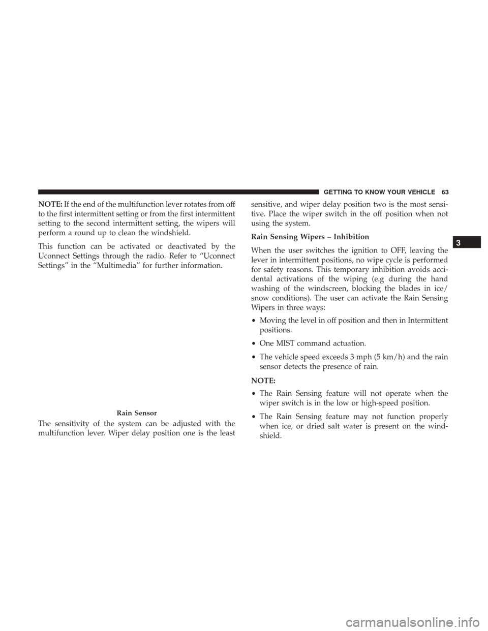
The sensitivity of the system can be adjusted with the
multifunction lever. Wiper delay position one is the least sensitive, and wiper delay position two is the most sensi-
tive. Place the wiper switch in the off position when not
using the system.
Rain Sensing Wipers – Inhibition
When the user switches the ignition to OFF, leaving the
lever in intermittent positions, no wipe cycle is performed
for safety reasons. This temporary inhibition avoids acci-
dental activations of the wiping (e.g during the hand
washing of the windscreen, blocking the blades in ice/
snow conditions). The user can activate the Rain Sensing
Wipers in three ways:
•
Moving the level in off position and then in Intermittent
positions.
• One MIST command actuation.
• The vehicle speed exceeds 3 mph (5 km/h) and the rain
sensor detects the presence of rain.
NOTE:
• The Rain Sensing feature will not operate when the
wiper switch is in the low or high-speed position.
• The Rain Sensing feature may not function properly
when ice, or dried salt water is present on the wind-
shield.
Rain Sensor
3
GETTING TO KNOW YOUR VEHICLE 63
Page 167 of 516
For further information, refer to “Privacy Practices” and
“Uconnect CyberSecurity” in “All About Uconnect Access”
in your Owner ’s Manual Radio Supplement and “Cyber-
security” in “Multimedia”.
EMISSIONS INSPECTION AND MAINTENANCE
PROGRAMS
In some localities, it may be a legal requirement to pass an
inspection of your vehicle’s emissions control system.
Failure to pass could prevent vehicle registration.For states that require an Inspection and Mainte-
nance (I/M), this check verifies the “Malfunction
Indicator Light (MIL)” is functioning and is not on
when the engine is running, and that the OBD II system is
ready for testing.
Normally, the OBD II system will be ready. The OBD II
system may notbe ready if your vehicle was recently
serviced, recently had a dead battery or a battery replace-
ment. If the OBD II system should be determined not ready
for the I/M test, your vehicle may fail the test. Your vehicle has a simple ignition actuated test, which you
can use prior to going to the test station. To check if your
vehicle’s OBD II system is ready, you must do the follow-
ing:
1. Cycle the ignition switch to the ON position, but do not
crank or start the engine.
NOTE: If you crank or start the engine, you will have to
start this test over.
2. As soon as you cycle the ignition switch to the ON position, you will see the “Malfunction Indicator Light
(MIL)” symbol come on as part of a normal bulb check.
3. Approximately 15 seconds later, one of two things will happen:
• The MIL will flash for about 10 seconds and then return
to being fully illuminated until you turn OFF the igni-
tion or start the engine. This means that your vehicle’s
OBD II system is not readyand you should notproceed
to the I/M station.
4
GETTING TO KNOW YOUR INSTRUMENT PANEL 165
Page 170 of 516
SAFETY FEATURES
Anti-Lock Brake System (ABS)
The Anti-Lock Brake System (ABS) provides increased
vehicle stability and brake performance under most brak-
ing conditions. The system automatically prevents wheel
lock, and enhances vehicle control during braking.
The ABS performs a self-check cycle to ensure that the ABS
is working properly each time the vehicle is started and
driven. During this self-check, you may hear a slight
clicking sound as well as some related motor noises.
ABS is activated during braking when the system detects
one or more wheels begin to lock. Road conditions such as
ice, snow, gravel, bumps, railroad tracks, loose debris, or
panic stops may increase the likelihood of ABS activa-
tion(s).
You also may experience the following when ABS activates:
•The ABS motor noise (it may continue to run for a short
time after the stop).
• The clicking sound of solenoid valves.
• Brake pedal pulsations.
• A slight drop of the brake pedal at the end of the stop. These are all normal characteristics of ABS.
WARNING!
•
The ABS contains sophisticated electronic equip-
ment that may be susceptible to interference caused
by improperly installed or high output radio trans-
mitting equipment. This interference can cause pos-
sible loss of anti-lock braking capability. Installation
of such equipment should be performed by qualified
professionals.
• Pumping of the Anti-Lock Brakes will diminish their
effectiveness and may lead to a collision. Pumping
makes the stopping distance longer. Just press firmly
on your brake pedal when you need to slow down or
stop.
• The ABS cannot prevent the natural laws of physics
from acting on the vehicle, nor can it increase brak-
ing or steering efficiency beyond that afforded by the
condition of the vehicle brakes and tires or the
traction afforded.
• The ABS cannot prevent collisions, including those
resulting from excessive speed in turns, following
another vehicle too closely, or hydroplaning.
(Continued)
168 SAFETY
Page 184 of 516
The BSM system notifies the driver of objects in the
detection zones by illuminating the BSM warning light
located in the outside mirrors in addition to sounding an
audible (chime) alert and reducing the radio volume. Refer
to “Modes Of Operation” for further information.The BSM system monitors the detection zone from three
different entry points (side, rear, front) while driving to see
if an alert is necessary. The BSM system will issue an alert
during these types of zone entries.
Entering From The Side
Vehicles that move into your adjacent lanes from either
side of the vehicle.
BSM Warning LightSide Monitoring
182 SAFETY
Page 188 of 516
Rear Cross Path (RCP)
The Rear Cross Path (RCP) feature is intended to aid the
driver when backing out of parking spaces where their
vision of oncoming vehicles may be blocked. Proceed
slowly and cautiously out of the parking space until the
rear end of the vehicle is exposed. The RCP system will
then have a clear view of the cross traffic and if an
oncoming vehicle is detected, alert the driver.
RCP monitors the rear detection zones on both sides of the
vehicle, for objects that are moving toward the side of the
vehicle with a minimum speed of approximately 1 mph(2 km/h), to objects moving a maximum of approximately
22 mph (35 km/h), such as in parking lot situations.
NOTE:
In a parking lot situation, oncoming vehicles can be
obscured by vehicles parked on either side. If the sensors
are blocked by other structures or vehicles, the system will
not be able to alert the driver.
When RCP is on and the vehicle is in REVERSE, the driver
is alerted using both the visual and audible alarms, includ-
ing reducing the radio volume.
WARNING!
Rear Cross Path Detection (RCP) is not a back up aid
system. It is intended to be used to help a driver detect
an oncoming vehicle in a parking lot situation. Drivers
must be careful when backing up, even when using
RCP. Always check carefully behind your vehicle, look
behind you, and be sure to check for pedestrians,
animals, other vehicles, obstructions, and blind spots
before backing up. Failure to do so can result in serious
injury or death.
RCP Detection Zones
186 SAFETY